All published articles of this journal are available on ScienceDirect.

The Seismic Performance Analysis of H-Shaped Steel PEC Columns
Abstract
The H-shaped steel PEC columns with concrete poured between flanges are different from the traditional steel-encased concrete columns. In this paper, the behaviors of H-shaped steel PEC columns with different parameters under axial loading and cycling loading have been simulated by using commercial software ANSYS. The results show: The fracture of the columns under axial loading and cycling loading mainly lies in the crush of concrete at the bottom of the columns. Because of the confined effect of steel, the stress distribution of specimens under axial loading display a V-shape. With the increment of the width of flanges, the confined effect becomes more obvious. Compared with H section steel columns, the bearing capacity has been increased. With the increment of axial compression ratio, the capacity has declined. The behaviors of the ductility and the energy dissipation capacity of H section steel PEC columns are good and dropped with the increment of axial compression ratio. At the initial stage, the average stiffness degenerates slowly. However, at the later stage, the average stiffness degenerates rapidly. Moreover, the degeneration becomes faster with the increment of compression ratio. The elastic stage, elastic-plastic stage and plastic stage are included in the skeleton curves. This study on the H-shaped steel PEC columns has important practical implications to the engineering.
1. INTRODUCTION
The whole H-shaped steel with the concrete encased is the traditional H-shaped steel concrete composite column. Based on the composite columns, the H-shaped steel partially encased concrete (PEC) columns, with the concrete poured between the flanges, have been put forward. Compared with H-shaped steel columns, the rigidity and bearing capacity of the H-shaped steel PEC columns are improved and the cross sectional area is reduced. Furthermore, the fire resistance ability of the H-shaped steel PEC columns is enhanced because of the reduction of the steel area on fire. Therefore, the H-shaped steel PEC columns play a role in the new construction and building reinforcement. This study started abroad, Elnashai, Elghazouli, et al. [1, 2] put forward a numerical model of PEC composite column. The elastic-plastic solid element was used for this model and constitutive model of axial hysteresis was applied for the concrete. PEC composite column had very little influence on the bending moment of the steel, but the ultimate bending moment was influenced by a certain degree, which indicated that the constraint conditions of concrete to some extent affected the ductility of PEC composite columns. Tremblay, Chicoine, et al. [3-5] simulated the short columns of PEC, and it indicated that the results of numerical simulation were agreed with the test results. The average ratio of bearing capacity of the test to the numerical simulation is 0.95. Prickett, Driver, et al. [6, 7] studied behaviour of partially concrete encased columns made with high performance concrete. This study shown that ductility of PEC made with high performance concrete lower than it of PEC made with normal strength concrete. In the domestic, Zhao Gentian, Yin Yingzi, et al. [8, 9] put forward a new style of encased steel concrete composite structure, which was called encased H-shaped steel concrete composite columns. According to the full range analysis about this kind of column under axial compression, the factors affecting the ultimate bearing capacity were analyzed, and it was compared with short columns of profiled steel reinforced concrete, and the advantages of this kind of encased steel concrete composite columns were recognized. Fang Youzhen, et al. [10, 11] put forward new PEC columns fabricated with crimping thin-walled built-up sections.4 specimens were designed and fabricated by full-scale. The tests of specimens were conducted with constant axial compression and low-cycle lateral reversed loading in the column strong axis, the load-displacement hysteretic curves were obtained. Base on the test results, the specimens’ relative performance were analyzed, including the load-carrying capacity, lateral stiffness, the seismic ductility and energy-dissipation capacity, the deformation pattern and failure mode. Yin Zhanzhong, et al. [12] presented the H-shaped steel PEC columns models and analyzed bond-slip constitutive relationship between the H-shaped steel and concrete by using ANSYS. All above studies reveal that the rigidity and bearing capacity of H-shaped steel PEC columns have been enhanced, and have good ductility and seismic behavior. However, up to now, the research is still at preliminary stage. The research results about seismic performance of the H-shaped steel PEC column are relatively small in amount. In this research, a finite element model of the H-shaped steel PEC column was established, and the performances of the H-shaped steel PEC columns under axial loading and cyclic loading were carried out by using the ANSYS.
2. FINITE ELEMENT MODELING
In this paper, the rigidity, bearing capacity, ductility and energy dissipation capacity of the H-shaped steel PEC columns were analyzed. The specimens are cantilever columns.
2.1. Geometric Parameter
The heights of the H-shaped steel PEC columns studied are 1m, 2m and 3m. A series of the H-shaped steel columns have been studied in this research. The parameters of the specimens are shown in Table 1. The sketch sections of H-shaped steel PEC columns and H-shaped steel columns are shown in Fig. (1). According to the code for seismic design of buildings in China, the formula of axial compression ratio is µ=N/(A×fc). N represents design values of axial force of PEC column, A represents cross-sectional area, and fc represents design value of axial compressive strength of concrete. C30 and C25 are the concrete strength grade.
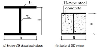
Sections figure of H-shaped steel columns and H-shaped steel PEC columns.
Parameter of specimens.
| Specimens | Section size(mm) H×B×Tw×Tf |
Calculating length L(m) |
Axial compression ratio | Slenderness ratio | Concrete grade |
|---|---|---|---|---|---|
| PEC-1 | 100×100×6×8 | 1 | 1/3 | 34.6 | C30 |
| PEC-2 | 100×100×6×8 | 1 | 1/2 | 34.6 | C30 |
| PEC-3 | 100×100×6×8 | 2 | 1/3 | 69.2 | C30 |
| PEC-4 | 100×100×6×8 | 2 | 1/2 | 69.2 | C30 |
| PEC-5 | 100×100×6×8 | 3 | 1/3 | 103.8 | C30 |
| PEC-6 | 100×100×6×8 | 3 | 1/2 | 103.8 | C30 |
| PEC-7 | 100×50×3.5×5 | 1 | 1/3 | 138.6 | C25 |
| PEC-8 | 100×50×3.5×5 | 1 | 1/2 | 138.6 | C25 |
| PEC-9 | 100×50×3.5×5 | 2 | 1/3 | 277.2 | C25 |
| PEC-10 | 100×50×3.5×5 | 2 | 1/2 | 277.2 | C25 |
| PEC-11 | 100×50×3.5×5 | 3 | 1/3 | 415.8 | C25 |
| PEC-12 | 100×50×3.5×5 | 3 | 1/2 | 415.8 | C25 |
| H-1 | 100×100×6×8 | 1 | 1/3 | 39.7 | - |
| H-2 | 100×100×6×8 | 2 | 1/3 | 79.4 | - |
| H-3 | 100×100×6×8 | 3 | 1/3 | 119.1 | - |
| H-4 | 100×50×3.5×5 | 1 | 1/3 | 88.3 | - |
| H-5 | 100×50×3.5×5 | 2 | 1/3 | 176.6 | - |
| H-6 | 100×50×3.5×5 | 3 | 1/3 | 264.9 | - |
2.2. Material Behaviors Modeling
1)The constitutive relation of adopted plain concrete Fig. (2a) in this paper is determined from Eq. (1).
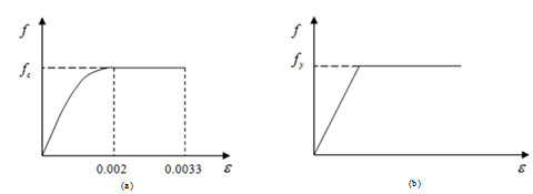
The figure of stress-strain relations.
 |
(1) |
1) The value of εo and εcu are 0.002 and 0.0033 respectively, recommended by Chinese Code for design of concrete structure. Design value of concrete tensile strength of C30 is 1.43 N/mm2, and C25 is 1.27 N/mm2.
2) The stress-strain relation of adopted steel Fig. (2b) is the ideal elastic-plastic model. Q235 is the grade of Chinese steel, and its yield value is 235MPa. Failure criteria of steel can be specified as the maximum mises stress.
2.3. Finite Element Type and Mesh
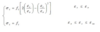
The H-shaped steel PEC columns were modeled by using solid elements, SOLID45 is used for the 3-D modeling of solid structures. The element is defined by eight nodes having three degrees of freedom at each node: translations in the nodal x, y, and z directions. The element has plasticity, creep, swelling, stress stiffening, large deflection, and large strain capabilities. A reduced integration option with hourglass control is available. The geometry, node locations, and the coordinate system for this element are shown in Fig. (3a). The element is defined by eight nodes and the orthotropic material properties. SOLID65 (see Fig. 3b) is used for the 3-D modeling of solids with or without reinforcing bars (rebar). The solid is capable of cracking in tension and crushing in compression. The element is defined by eight nodes having three degrees of freedom at each node: translations in the nodal x, y, and z directions. The concrete element is similar to the SOLID45 (3-D Structural Solid) element with the addition of special cracking and crushing capabilities. The most important aspect of this element is the treatment of nonlinear material properties. The concrete is capable of cracking (in three orthogonal directions), crushing, plastic deformation, and creep. The rebar are capable of tension and compression, but not shear. They are also capable of plastic deformation and creep. The William—Warnke model (The value of open shear transfer coefficient and closed shear transfer coefficient are taken as 0.6 and 1.0 , respectively) was selected for the failure criterion of concrete . In the real test, shear connector was set between concrete and steel, in the circumstance of the existence of shear connector, the bond–slip relationship between steel and concrete wasn’t considered, Boolean operation was applied to glue steel and concrete together. Swept meshing method was applied for the specimen, employing elements size with 15mm in the x axis direction, 15mm in the y axis direction, and 16mm in the z axis direction. The precision of the specimen met the requirements. In order to avoid loading stress concentration, the steel plates with thickness of 20mm are added on loading end and fixed support. The model after meshing is shown in Fig. (4).
Figures of geometries of solid45 and solid65.
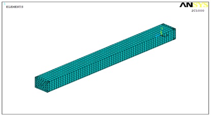
The figure of the model after meshing.
2.4. Load Application
Firstly, apply the constant axial loading to the bottom of the columns, and then the lateral displacement with the direction of strong axis is applied until the failure of H-shaped steel PEC columns. The lateral displacement value applied on the H-shaped steel is the same with H-shaped steel PEC column. On the cycling loading condition, the constant axial loading is applied, then the cycle lateral displacement is applied by using displacement increment method, and before the column fractured, per level of displacement increment is 0.5 Δy, per level of displacement cycles once. Δy is the displacement value obtained by one-way loading, its value is the corresponding position of the turning point of the P-Δ curve.
3. ANALYSIS AND RESULT
The ultimate displacement of column upper end is Δu, and the ultimate bearing capacity of column is Pu in case of the failure condition of the PEC columns. The P-Δ curves of PEC columns under the circumstances of axial loading are shown in Fig. (5).
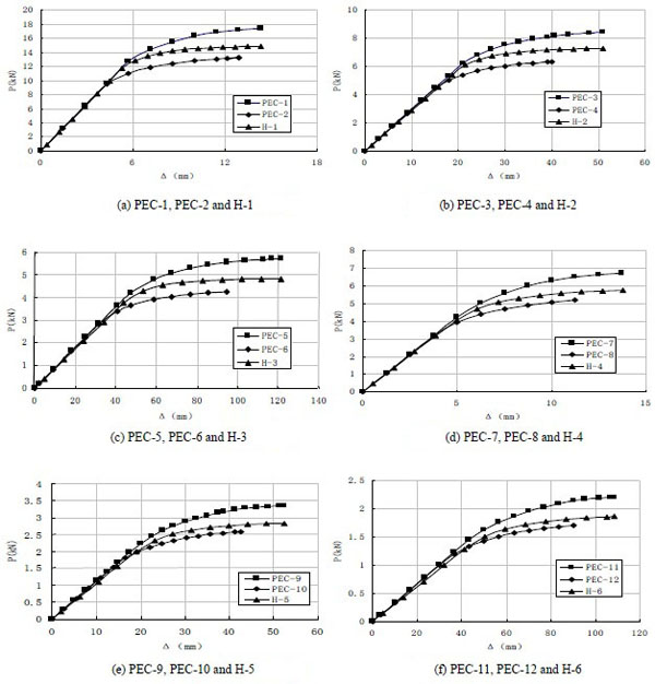
Figure of P-Δ Curves.
3.1. Bearing Capacity Analysis
The bearing capacity of PEC column is shown in Table 2.
Bearing capacity of PEC columns.
| Specimens | PEC-1 | PEC-2 | PEC-3 | PEC-4 | PEC-5 | PEC-6 | PEC-7 | PEC-8 | PEC-9 |
|---|---|---|---|---|---|---|---|---|---|
| Pu(kN) | 17.48 | 13.25 | 8.42 | 6.35 | 5.71 | 4.24 | 6.72 | 5.21 | 3.34 |
| specimens | PEC-10 | PEC-11 | PEC-12 | H-1 | H-2 | H-3 | H-4 | H-5 | H-6 |
| Pu(kN) | 2.60 | 2.21 | 1.71 | 14.90 | 7.29 | 4.82 | 5.74 | 2.82 | 1.87 |
Compared with H-shaped steel columns, the bearing capacity of H-shaped steel PEC columns with the same parameters is increased, with the increment of 17.50% on average. The bearing capacity of the columns is declined with the increment of calculating length. The reason lies in the bending moment which causes concrete crush with the increment of lateral force and p-δ effect. The bearing capacity of specimens is declined with the same geometric parameters and different axial compression ratio with the parameters from 1/2 to 1/3.
3.2. Ductility Analysis
Define the ductility factor as µ=Δu/Δy, and define the relative deformation as ∂=Δu/L when considering slenderness. The initial stiffness, the ductility factor and the relative deformation of each column are shown in Table 3, all ductility factors of the PEC columns are more than 2.3, and these results show that the ductility is good. The PEC column is created by pouring concrete in the groove, and the groove is formed with the web and flange of H-shaped column. Due to the constraint of web and groove of H-shaped steel column, the concrete is in three-dimensional pressure state. Meanwhile, local buckling of steel will not occur due to the existence of concrete. As a result, the PEC columns have the advantages of both concrete and steel, which can improve the ductility and bearing capacity.
The ductility factor and the relative deformation of columns.
| Specimens | Yielding displacement Δu(mm) |
Ultimate displacement Δu(mm) |
Relative deformation ∂ |
Ductility factor µ |
|---|---|---|---|---|
| PEC-1 | 4.8 | 14.3 | 0.0143 | 2.98 |
| PEC-2 | 4.2. | 12.2 | 0.0122 | 2.90 |
| PEC-3 | 20.1 | 50.3 | 0.0252 | 2.50 |
| PEC-4 | 17.0 | 40.0 | 0.0200 | 2.35 |
| PEC-5 | 47.5 | 121.4 | 0.0400 | 2.55 |
| PEC-6 | 40.1 | 94.8 | 0.0316 | 2.36 |
| PEC-7 | 5.8 | 13.8 | 0.0138 | 2.37 |
| PEC-8 | 4.8 | 11.1 | 0.0111 | 2.31 |
| PEC-9 | 21.2 | 52.5 | 0.0263 | 2.47 |
| PEC-10 | 17.8 | 42.4 | 0.0212 | 2.38 |
| PEC-11 | 46.1 | 114 | 0.0380 | 2.47 |
| PEC-12 | 38.2 | 90 | 0.0031 | 2.35 |
For PEC-11 and PEC-12 in Fig. (5), H-shaped steel columns haven’t been fractured when lateral displacements reach to the maximum values. However, due to the large scale of axial compression ratio, most pressed area of the concrete crushed earlier, making PEC columns fractured.Thus, the ductility factors don’t have effect on these kinds of H-steel columns.
Under the circumstance of same section size, compared PEC-1, PEC-3, PEC-5 with PEC-2, PEC-4, PEC-6, and also compared PEC-7, PEC-9, PEC-11with PEC-8, PEC-10, PEC-12, respectively. The comparison results exhibit that ultimate displacements are significantly decreased by 14.7%, 20.6%, 21.9% and 19.6%, 19.2%, 21% respectively, with the increment of compression ratio from 1/3 to 1/2. Meanwhile, ductility factors are reduced by 2.6%, 6%, 7.5% and 2.5%, 3.6%, 4.8%, respectively. The ductility factor is declined with the increment of the slenderness ratio.
Moreover, study the relationship between slenderness ratio and relative deformation ∂, it is found that the ductility factor is increased with the increment of the slenderness ratio among the PEC columns mentioned above.
3.3. Failure Mode
The ultimate compressive strain distribution of the concrete and stress distribution of specimens are shown in Figs. (6) and (7).
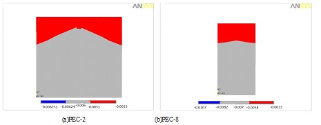
The distribution of ultimate compressive strain of concrete.
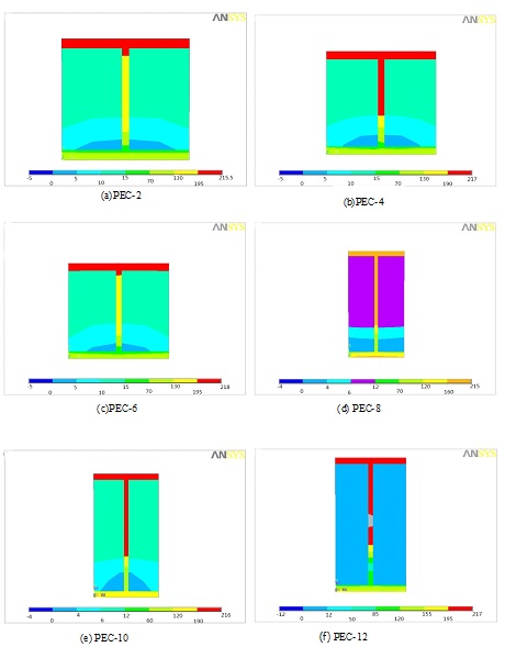
The stress distribution of specimens.
In Fig. (6), the red zone is compressive strain exceeding ultimate compressive strain of concrete, which will crush in real test.
From Fig. (6), the failure of the PEC column lies in the crush of the part of the compressive zone of concrete. The shape of ultimate compressive strain distribution is V-shape, because of the concrete confined by the steel. Compared Fig. (6a) with Fig. (6b), the shapes of ultimate compressive strain distribution are quite different from each other under the circumstance of different confined effect. Moreover, the confined effect becomes obvious with the increment of the width of flanges.
The Fig. (7) shows the shapes of stress distribution of the PEC columns reaching to the ultimate displacement. It can be seen that the zone of compressive stress of concrete which exceeds ultimate compressive stress defined in material behaviors modeling is bigger than the zone of ultimate compressive strain of concrete in Fig. (6). The reason is that the confined effect by steel limits the deformation of concrete. Because of the weak confined effect, the shapes in (d), (e) and (f) are similar with those concrete columns.
3.4. Energy Dissipation Analysis
3.4.1. Hysteretic Curves
Hysteretic curves are shown in Fig. (8).
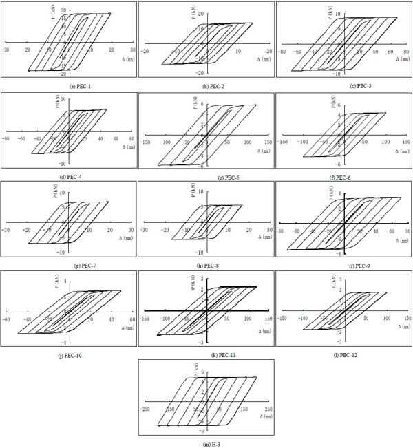
Figures of hysteretic curves of specimens.
Fig. (8) shows that the hysteretic curves of the H-shaped steel PEC columns are plump and the H-shaped steel PEC columns have good energy dissipation capacity. The ultimate displacement and the bearing capacity of H-shaped steel PEC columns with same section and calculating length are decreased obviously with the increment of axial compression ratio from 1/3 to 1/2. Meanwhile, the ultimate displacement and the bearing capacity of H-shaped steel PEC columns with same section and compression ratio are declined obviously with the increment of the slenderness ratio.
3.4.2. Energy Dissipation Analysis
According to the Specification of testing methods for earthquake resistant building, the seismic behavior can be measured by using the energy dissipation coefficient E. The energy dissipation coefficient E can be determined by Eq. (2) and the calculation figure of energy dissipation (see Fig. 9)
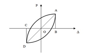
The calculation figure of energy dissipation.
 |
(2) |
The energy dissipation coefficients of the maximum hysteretic curve are shown in Table 4.
The energy dissipation coefficients.
| Specimens | PEC-1 | PEC-2 | PEC-3 | PEC-4 | PEC-5 | PEC-6 | PEC-7 |
|---|---|---|---|---|---|---|---|
| E | 2.32 | 2.09 | 2.16 | 2.00 | 2.01 | 1.92 | 2.33 |
| specimens | PEC-8 | PEC-9 | PEC-10 | PEC-11 | PEC-12 | H-3 | |
| E | 1.92 | 2.37 | 1.95 | 1.98 | 1.71 | 2.78 |
The comparison of PEC-5 and H-3 shows that the H-shaped steel PEC columns have the lower energy dissipation effect than those of the H-shaped steel columns. The phenomenon relies on the higher stiffness, worse ductility of the H-shaped steel PEC columns, the concrete crushing and cracking early at the bottom of H-shaped steel PEC columns under the cycling loading.
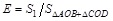
Average stiffness of PEC-11and PEC-12.
3.4.3. Stiffness Deterioration
Define the average stiffness as K=(K++K-)/2. The average stiffness deterioration curves of PEC-11 and PEC-12 under cycling loading are shown in Fig. (10). The average stiffness is declined obviously. At the initial stage, the average stiffness degenerates slowly, while it degenerates rapidly at the later stage. Moreover, stiffness degeneration becomes faster with the increment of compression ratio from 1/3 to 1/2.
3.5. Skeleton Curves
In this paper, only the skeleton curves of PEC-5 and PEC-10 are listed in the Fig. (11). For the others have the same properties.
Fig. (11) shows that the shape of skeleton curve is similar with the shape of P-Δ curves in Fig. (5), while the bearing capacities are lower than the H-shaped steel PEC columns. Elastic stage, elastic-plastic stage and plastic stage are included in the curves. Meanwhile, the yield displacements in skeleton curves above are respectively 48mm and 18.2mm, close to the yield displacements of the PEC columns under the axial loading.
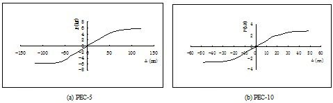
Skeleton curves of PEC-5 and PEC-10.
CONCLUSION
The failure of H-shaped steel PEC columns under axial loading and cycling loading lies in the crush of the concrete. Owing to the concrete confined by the steel, the shapes of ultimate compressive strain distribution and shapes of the stress distribution are both V-shape. The confined effect also becomes obvious with the increment of the width of flanges.
Compared with the H-shaped steel columns, the bearing capacity and the stiffness of the H-shaped steel PEC columns are improved. From the analysis, the bearing capacity is declined with the increment of compression ratio from 1/3 to 1/2.
Under axial loading condition, all ductility factors of the PEC columns are more than 2.3 and these results show that the ductility is good. And the ductility is declined with the increment of compression ratio from 1/3 to 1/2.Under the cycling loading, the hysteretic curves are plump. Meanwhile, all the energy dissipation coefficients are between 1.7 and 2.4, this shows that the H-shaped steel PEC columns have good energy dissipation capacity. In addition, the energy dissipation capacity is declined with the increment of axial compression.
At the initial stage, the average stiffness degenerates slowly and at the later stage it degenerates rapidly. The degeneration becomes faster with the increment of compression ratio from 1/3 to 1/2.
Shapes of skeleton curve are similar with the shapes of the curves of PEC columns under axial loading. The elastic stage, elastic-plastic stage and plastic stage are included in the skeleton curves.
NOTATIONS
CONFLICT OF INTEREST
The authors confirm that this article content has no conflict of interest.
ACKNOWLEDGEMENTS
This research is supported by National Nature Science Foundation Project (No.51368037, No.51568040), the Fundamental Research Funds for the Gansu Universities, the Project of Green and Energy Conservation Architecture of Gansu province, Alumni Foundation of Civil Enginneering 77, Lanzhou University of Technology.

