All published articles of this journal are available on ScienceDirect.

Dynamic Responses of RPC-Filled Steel Tubular Columns Post Fire Under Blast Loading
Abstract
Blast-resistant capacities of 4 large scale circular Reactive Powder Concrete Filled Steel Tubular (RPC-FST) columns after exposure to fire are experimentally examined. The overpressures of shock wave, the deflections and strains of RPC-FST column specimens are recorded by advanced gauges. The influences of fire durations and scaled standoff distances of explosive charge on the dynamic behaviors and failure modes are discussed. It is shown that the RPC-FST columns remain excellent blast-resistant capacities after exposure to fire. RPC core column can be effectively confined by steel tube, but the blast-resistant capacities of RPC-FST columns are decreased as explosive charge or fire duration increased. The failure modes are transited from bending types to bending-shear types as explosive charge increased, and an obvious plastic hinge at mid-span section can be observed in the RPC-FST column with fire duration of 105min. It is also indicated that the maximum displacements of RPC-FST columns are more sensitive to fire duration than to explosive charge weight.
1. INTRODUCTION
Some special structures are designed in order to resist to exceptional events. For instance, defense works, military building or strategic constructions may need to sustain blast loads caused by missiles. But the events of September 11, 2001, have changed the way we consider the design of our critical infrastructure. The collapsing of the World Trade Centre is caused simultaneously by high temperature and by shock wave. In addition, the material performances will be degraded after exposure to fire, but many these special constructions are still used for blast-resistant structures with enough strength and ductility. Therefore, it is necessary to reassess the blast-resistant reliabilities of the structures that have been exposed to fire or high temperature. Concrete Filled Steel Tubular (CFST) structures are widely used in civil engineering structures, such as high-rise buildings, large-span bridges and electricity transmission towers due to their excellent performances. Reactive Powder Concrete Filled Steel Tube (RPC-FST) is a member of CFST, and regarded as a new fire-resistant and blast-resistant composite structure with good exploitation potential and application prospects due to a series of advantages as high strength, high rigidity, good plasticity and ductility. In recent years, RPC-FST is usually used as load-bearing member of major engineering.
A large number of researches on CFST structures under various loading conditions have been carried out in the last few decades [1]. Impact/blast load is an important and common load which can cause severe damage to structures like high-rise buildings and large span bridges. However, limited works have been conducted on CFST structures under blast loading, in particular RPC-FST structures after exposure to fire or high temperature. Han et al. [2] presented that a set of new test data for high strength CFST members subjected to transverse impact, and a Finite Element Analysis (FEA) model is established to predict the dynamic behavior of high strength CFST members. Finally, a simplified model is obtained based on a parametric analysis to predict the flexural capacities of CFST members under impact loading. Tests of CFST beams under transverse impact have also been carried out by other authors. Bambach et al. [3] and Remennikov et al. [4] experimentally studied the transverse impact behavior of square CFST members. Deng et al. [5] conducted drop hammer impact tests on simply supported circular CFST beams. Numerical work on the impact loading of CFST beams has also been conducted by Yousuf et al. [6], Wang et al. [7] and Bambach [8]. The carrying capacities of axial impact were performed experimentally by several researchers. Xiao et al. [9] performed similar tests on CFST stub columns with a Split Hopkinson Pressure Bar (SHPB). A simplified calculation method for the axial strength of CFST was derived from the test results. Some works have been carried out on impact strength in condition of high temperature. Huo et al. [10] studied the axial behavior of CFST columns under the combined effects of impact (impact velocity 12~16m/s, hammer weight 524.2kg) and elevated temperature (up to 400°C with duration 40min), and showed that CFST columns have ductile behavior under impact loading and remain excellent impact-resistant capacities under high temperature. High temperature, impact velocity, impact energy and steel ratio have remarkable effect on dynamic behaviors of CFST columns, but the influences of axial load level were not noticeable. With the RPC-FST, experimental investigation into impact-resistant behavior of RPC-FST columns was conducted by Tian et al. [11] using SHPB system, and dynamic responses of the columns under axial impact loading were studied by means of numerical simulation method. Increase coefficient of load carrying capacity and ratio of load carrying capacity between steel tube and RPC core column were obtained. Due to the interaction of the confined RPC with a steel tube outside, the bearing capacity of the RPC can be enhanced greatly under dynamic loading. The bearing capacity of RPC-filled steel tubular column under the positive impulse loading with a time period of no more than 0.5 ms can increase by at least 60%. A few works have been carried out for the blast-resistant capacities of CFST at present. Behaviors of CFST column under blast loading were studied experimentally and numerically by Huang [12], Wu [13] and Cui [14], it was indicated that the blast-resistant capacities of CFST members were greatly decreased and the failure modes tend to bending-shear types. Finite element analysis on dynamic response and damage mode of Tube-Confined Concrete Column under explosion is carried out by Du [15]. The results showed that core concrete are serious damage, but the circular columns have better blast-resistant capacities than square columns. Multi-hazard resistant bridge piers having CFST under blast loading were studied experimentally by Shuichi Fujikura et al. [16], it was found that prototype bridge CFST columns can be designed to provide both satisfactory seismic performance and adequate blast resistance.
The blast-resistant mechanisms of RPC-FST columns after exposure to fire are still not clear due to the coupling influences of temperature effect, strain rate effect, and inertial effect. In order to examine the blast-resistant capacities of RPC-FST columns after exposure to fire, blast tests for 4 large scale RPC-FST columns are performed. The influences of fire duration and scaled standoff distance on strains, displacements and failure types of RPC-FST specimens are discussed.
2. TEST PROGRAMS
Four large-scale specimens, including one circular RPC-FST specimens without fire and three circular RPC-FST specimens after exposure to fire are fabricated. A series of blast tests are performed at the Large Scale Blast-Resistant Test Site, PLA University of Science and Technology. The main test parameters include: axial force, standard fire duration, and explosive charge weight. All specimens are manufactured from the same batch of steel tubes with diameter D=194mm, thickness ts=6mm, and length L=2500mm. In order to simulate the actual working condition, each specimen is constrained with fixed supports and a constant axial force is applied on the end plate by air cylinder. The blast loads are applied by spherical explosive charge, and a near-field air blast is considered in this test. Detailed information about all specimens is presented in Table 1, where W is the explosive charge weight, and H is the standoff distance. t is the fire duration, then temperature can be determined by T=T0+345lg(8t+1) according to reference [17], where T0 is the room temperature.
Detail information for RPC-FST specimens.
| Cases | Specimens | Fire durations t (min) |
Charge weights W (kg) |
Standoff distances H (mm) |
Scaled standoff distance |
|---|---|---|---|---|---|
| 1 | RPC-FST1 | 0 | 17.5 | 1500 | 0.58 |
| 2 | RPC-FST3 | 60 | 17.5 | 1500 | 0.58 |
| 3 | RPC-FST4 | 60 | 35 | 1500 | 0.48 |
| 4 | RPC-FST5 | 105 | 17.5 | 1500 | 0.58 |
Note that a constant force of N=754 kN is applied on every specimen along its neutral axis.
2.1. Material Properties
Seamless steel tubes are selected to confine the core concrete. The properties for three circular hollow steel tubes are determined from two tensile coupon tests. Table 2 shows the average Yield stress (fy), Young's modulus (Es) and Poisson’s ratio (ν) for the steel tube. Reactive Powder Concrete (RPC) is used for the core concrete in all RPC-FST specimens. The mix proportions are as follows: Cement: 394kg/m3; Fly ash: 110kg/m3; Quartz sand (0.3-0.6μm): 295kg/m3; Quartz sand (0.4-0.7μm): 146kg/m3; Standard sand: 154kg/m3; Water: 170 kg/m3; Additional high-range water reducer (HRWR): 13kg/m3. The average cube compressive strength (fcu) and the Young's modulus (Ec) at 28 days are 116.2MPa and 34.2GPa, respectively.
Material properties of steel tube and RPC.
| Materials | Yield strengths (MPa) | Compressive strength (MPa) | Young's modulus (GPa) | Poisson’s ratio |
|---|---|---|---|---|
| Steel tubes | 350 | 370 | 206 | 0.28 |
| RPC | - | 116.2 | 34.2 | 0.19 |
2.2. Specimen Fabrications
Four large-scale cold-formed RPC-FST columns with the same lengths and the same boundary conditions are used for the specimens. Two sizes of square steel plates, with side lengths B=300mm are designed as end plates. Four stiffeners are welded between the end plates and the steel tube surfaces to connect the specimen to the support with high strength bolts, ensuring that the constant axial force can be applied to the end plates. The strain gauges are pasted on the surfaces of steel tubes when they are carried to the test site, as shown in Fig. (1). The wires are connected to the strain gauges and ensured that they can work well. Other gauges such as pressure gauges and deflection gauges are prepared when the specimens are fixed on the self-balancing reaction frame.
Image of specimen fabrications.
2.3. Test Procedure
The purposes of the test are to reveal the influences of fire durations and explosive charge weights on the dynamic responses of RPC-FST columns. ISO-834 standard fire exposure tests are conducted in the Fire Stove at China Southeast University after RPC-FST specimens being natural cured for 28 days. The fire durations are 0min for specimen RPC-FST1, 65min for specimen RPC-FST3 and RPC-FST4, and 105min for specimen RPC-FST5 as given in Table 1.
Blast tests are carried out in Blast-Resistant Test Site the as specimens are cooled enough. The test set-up includes reinforced concrete foundation, self-balancing reaction frame, air cylinder and fixed support. The end of RPC-FST columns is connected to the square endplates, and fixed on the self-balancing reaction frame. The blast load produced by the explosive charge just above the center of RPC-FST specimen, and the standoff distance of explosive charge is 1500mm, the distance of the blast load from the end plate is 1953mm. Explosive charge is detonated by an electric detonator while everything is ready. Recorded parameters include overpressure of shock wave, deflection of specimen and strain on steel tube surface. The recorded arrangement is displayed in Fig. (2), where Pi represents the pressure recorded point, Si represents the strain recorded point and Di represents the deflection recorded point. The fixed boundary condition is achieved by connecting one end plate of the specimen to the reaction frame using high strength bolts, and connecting another end plate to the piston of air cylinder. In order to eliminate the influences of specimens’ deformations, the blast load is recorded using a pressure gauge fixed on the concrete foundation. The deflections are recorded with three deflection gauges fixed uniformly on behalf of specimen. The constant axial force can be recorded by pressure gauge throughout blast test.
Recorded arrangement of blast test.
3. TEST RESULTS AND DISCUSSIONS
3.1. Variations of Overpressure (P) Versus Time (t)
The explosive charge weight with 17.5kg or 35kg TNT is used to produce air blast, corresponding to scaled standoff distance of 0.58m/kg3 and 0.48m/kg3, respectively. The recorded overpressures for different recorded points are summarized in Table 3.
Overpressure of measuring point.
| Cases | Charge weights W (kg) |
Overpressure for P1 (MPa) |
Overpressure for P2 (MPa) |
Overpressure for P3 (MPa) |
|---|---|---|---|---|
| 1 | 17.5 | 15.38 | 32.76 | 75.60 |
| 2 | 17.5 | 17.46 | 37.20 | 74.81 |
| 3 | 35 | 39.96 | 68.25 | 83.81 |
| 4 | 17.5 | 14.65 | 34.51 | 70.48 |
The recorded overpressures for different recorded points are summarized in Table 3, and the variations of overpressure (P) versus time (t) for case 4 are given in Fig. (3). The typical time-histories of overpressure versus time are derived, but the loads produced by the air blast can be considered as non-uniformly distributed because it is in the scope of near-field detonations. It can be seen in Fig. (3) that the overpressures rise rapidly to the maximum values and attenuated slowly.
Variations of overpressure versus time.
3.2. Failure Modes
The influences of fire duration and explosive charge weight on dynamic responses and failure modes are analyzed in this section. The residual deformations of specimens in different conditions are displayed in Fig. (4). It is apparent that, no obvious deflections can be observed in the RPC-FST specimens without fire exposure (RPC-FST1). However, severe deformations occur in specimens after exposure to fire, moreover the deformations tend to obvious as fire duration or explosive charge weight increased. No cracks and spallings can be observed in all specimens, it means that the RPC core column can be effectively confined by outer steel tubes, and the excellent blast-resistant capacities and good ductility of RPC-FST are experimentally verified.
Post-test of RPC-FST specimens.
3.2.1. Influences of Fire Duration
The maximum and residual deflections of RPC-FST specimens with different fire durations are shown in Fig. (5), where the recorded data are linked by straight lines. It is observed that bending deformations occur in all specimens, the maximum displacements increased greatly as fire durations increased. The figures of residual deformation show that the residual deflection of specimen with fire duration of 0min, as shown in solid line in Fig. (5b), is obviously smaller than that of with fire duration of 65min or 105min, it means that the deformations are transited from the elastic range to the plastic range with increased fire duration. It is important to notice that the plastic hinge tends to be more obvious as fire duration increased from 65min to 105min. Furthermore, a curve of residual deflection with ‘V’ shape is observed if fire duration is up to 105min because that only one plastic hinge is formed at its mid-span section. As shown in dotted line in Fig. (5b) that the axis of the specimen RPC-FST3 or RPC-FST5 remained almost straight, therefore bending failure is the main failure type for RPC-FST columns after exposure to fire. The reasons might be that the strengths of steel tube and RPC are degraded with high temperature, a plastic hinge is easily formed under blast loading, and most of explosive energies are transformed into the kinetic energies with plastic rotations around the hinge. On the other hand, the axial force would also result in increasing mid-span deflection once the initial deflection occurs with plastic hinge deformed.
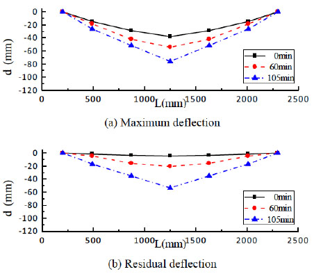
Influences of fire duration on deflections.
3.2.2. Influences of Scaled Standoff Distance
The influences of scaled standoff distance on deflections of RPC-FST specimens with the same fire durations are given in Fig. (6). Explosive charge weights of 17.5kg and 35kg TNT, corresponding to scaled standoff distances of 0.58m/kg1/3 and 0.48m/kg1/3 are discussed, respectively. A smooth deflection curve is derived for either RPC-FST specimen, and it is similar to the deflection curve of beam member under static loading. It is observed that there are three plastic hinges in specimens, one at the mid-span, two near to the fixed ends. The deflection curves seem smoother than that of RPC-FST3 or RPC-FST5. Typical bending deformations occur in the specimens with scaled standoff distance of 0.58m/kg1/3, but the failure modes tend to bending-shearing type for specimens with scaled standoff distance of 0.48m/kg1/3 due to two hinges near to the fixed ends become more obvious. No cracks and obvious plastic hinge can be observed at the mid-span section, and a smooth curve of residual deflection with ‘U’ shape can be seen, as shown in dotted line in Fig. (6b).
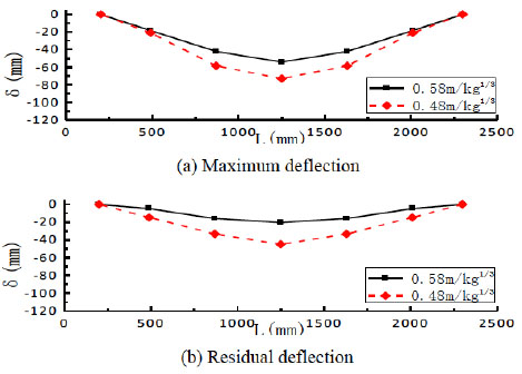
Influences of scaled standoff distance on deflections.
3.3. Mid-Span Displacements
The maximum displacements and residual displacements of all measuring points are summarized in Table 4. It can be seen that the maximum and residual displacements of all specimens are increased as explosive charge weights or fire durations increased. The ratios of maximum displacement to full length of specimen (i.e. relative displacements) are all more than 2% except RPC-FST1, it means that the RPC-FST specimens after exposure to fire are all satisfied the transverse ultimate carrying capacities [18]. With respect to case 2, it is indicated that the residual displacements of D3 for case 3 and case 4 are increased by 118.0% and 161.5%, respectively. It means that the residual displacements of RPC-FST specimen are more sensitive to fire durations than to explosive charge weights. The displacement obtained from case 4 is much larger because the curvature is localized at the mid-span section due to the formation of a plastic hinge, thus the column fails with a relatively large deflection. On the other hand, for case 3 the curvature is distributed along the whole specimen due to bending-shearing tendency, hence the specimen undergoes a smaller displacement before reaching the ultimate limit state.
Results summarizations of blast test.
| Case | Maximum displacement (mm) | Residual displacement (mm) | Relative displacements (%) | ||||
|---|---|---|---|---|---|---|---|
| D1 | D2 | D3 | D1 | D2 | D3 | ||
| 1 | 14.65 | 28.60 | 38.15 | 1.86 | 3.64 | 4.68 | 1.82 |
| 2 | 18.44 | 42.09 | 54.17 | 4.85 | 15.82 | 20.56 | 2.58 |
| 3 | 21.07 | 58.51 | 72.92 | 14.81 | 33.37 | 44.83 | 3.47 |
| 4 | 26.24 | 51.46 | 75.90 | 17.03 | 34.95 | 53.76 | 3.61 |
3.4. Time-Histories of Displacement
Time-histories of displacement are displayed in Fig. (7). As shown in Fig. (7a), the displacements of RPC-FST1 rise rapidly and an obvious rebounding process can be observed, but the residual displacements tend to zero finally. The maximum displacement of D3 is only 38.15 mm, about 1.82% the full length of specimen. It means that the RPC-FST column with fire duration of 0min is in the elastic state. Time-histories of displacement of RPC-FST3 are displayed in Fig. (7b).
The deflection curves are smooth, which are slightly similar to that of RPC-FST1. There is not obvious plastic hinge can be observed at mid-span section, in addition the space between the curves of maximum deflection and residual deflection are relatively plump, hence it has a good elastic recovering capacity and excellent energy absorption capacity. Time-histories of displacement for specimen with fire duration of 60min subjected to blast loading of 35 kg TNT are shown in Fig. (7c). They are similar to that of RPC-FST3, but the maximum displacements and residual displacements are larger than that of RPC-FST3. The space between the curves of maximum deflection and residual deflection became narrow. It means that the failure types tend to bending-shear failure, and the recovering capacities are decreased. Time-histories of displacement for specimen with fire duration of 105min subjected to blast loading of 17.5 kg TNT are shown in Fig. (7d).
It is indicated that the time-histories of recorded points are smoother than above specimens, and the space between measuring D1, D2 and D3 are relatively large. The reasons might be that the elastic resilience of RPC-FST column is greatly decreased after exposure to high temperature, and the RPC-FST column is in the plastic state entirely. The space between the curves of maximum deflection and residual deflection became so narrow, and bending failure occurs. Thus the blast-resistant capacities are greatly decreased for RPC-FST specimens with fire duration of 105min.
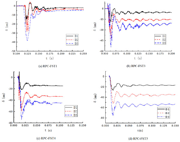
Time-histories of displacement.
CONCLUSION
Blast test on four large scale RPC-FST columns after exposure to fire are carried out, the influences of explosive charge weight and fire duration on dynamic behaviors and failure types are investigated.
It is indicated that bending deformations occur in all RPC-FST columns, the maximum displacements and residual displacements of RPC-FST columns are increased as explosive charge weights or fire durations increased. The maximum displacements increased greatly as fire durations increased due to the formation of a plastic hinge at its mid-span section. The deformations are transited from the elastic range to the plastic range with fire duration increased.
It is important to notice that the plastic hinge tends to more obvious as fire duration increased from 60min to 10 min, furthermore a curve of residual deflection with ‘V’ shape is observed if fire duration is up to 105min. Typical bending deformations occur in the RPC-FST columns with scaled standoff distance of 0.58 m/kg1/3, but the failure modes tend to bending-shearing failure for RPC-FST column with scaled standoff distance of 0.48 m/kg1/3, and a smooth curve of residual deflection with ‘U’ shape can be seen.
CONFLICT OF INTEREST
The authors confirm that this article content has no conflict of interest.
ACKNOWLEDGEMENTS
The authors gratefully acknowledge the financial support from the National Natural Science Foundation of China (Grant: 51378498, 51578541) and the natural science foundation (Grant: Bk20141066) of jiangsu province).

