All published articles of this journal are available on ScienceDirect.

Comparison of Soil Pressure Calculating Methods Based on Terzaghi Model in Different Standards
Abstract
Soil pressure calculation method for Trenchless pipe based on the Terzaghi Soil Arching Theory have been defined in Chinese national standard GB50332-2002, North America standard ASTM F1962-09 and European standard BS EN 1594-2009. At present, the calculation results from all of the three standards have shown discrepancies with the measured soil pressure. There is little research on the issue of discrepancies in each standard based on the same Terzaghi soil arching theory. The comparison has been made to investigate the differences among all the three standards. The conclusions can be made that the calculation in both GB50332 and ASTM F1962 ignores the cohesion and compressibility of the soil, using the same method to calculate sand soil and clay soil, and does not fully consider the effect of the internal friction angle of soils, which lead to a small impact of the soil properties on the arching factor. The BS EN 1594 standard considers the cohesion strength of soils and uses two different methods for pressure of sand soil and clay soil, respectively; The comparisons show that the cohesion strength has a significant impact on soil pressure, and that the former two standards showed a higher soil pressure than BS EN 1594 since both of them ignored the cohesion strength of soils.
1. INTRODUCTION
Trenchless technology has been developed for many years to install new pipelines, such as sewers, pressurized water and gas pipes [1]. The trenchless construction methods include horizontal directional drilling (HDD) and pipe jacking methods by which pipelines can be installed with little excavation of the ground [2]. Trenchless technologies are considered to be the most beneficial trenching techniques in civil engineering. In China, North America and Europe, pipelines for HDD installation are usually designed using GB 50332-2002 (abbreviated as GB standard), ASTM F 1962-2009 (abbreviated as ASTM standard) and BS EN 1594-2009 (abbreviated as EN standard) [3-5]. Based on those standards, pipelines are designed against operational loads, and in most cases of deep installations, the greatest pressure on a pipe crown in operational conditions is earth pressure. It is essential to accurately determine the soil pressure since it affects the wall thickness design of the pipeline. A thicker pipeline, with smaller Dimension Ratio (DR) can resist higher earth pressures. The magnitude of soil pressure on a trenchless pipeline is dependent upon the soil properties of the borehole. If the soil is stable after the drilling, for instance a very deep buried borehole, a soil arching forms to resist all of soil pressure and the pressure burdening on the pipeline is zero. A sliding wedge develops in case of insufficient burial depth [6]. This is due to the bore deformation caused by the overcut and the pipeline deformation due to the existing loading conditions. The mobilized shear force on both sides of the wedge along the two sliding surfaces partially bears the weight of soil column. Therefore, the soil pressure applied on pipelines is less than the soil column weight. This soil arching is known as Terzaghi soil arching. All of the soil pressure calculating methods for trenchless pipelines in the mentioned three design standards are based on the Terzaghi soil arching model. For buried pipelines, Marston [7] proposed a method for calculating earth pressure for the first time known as Marston formula. Terzaghi put forward another formula based on trap door experiments. Stein et al. [8] applied the Terzaghi soil arching model for determining earth pressure and trenchless pipe design. At present, the Terzaghi soil arching model has been widely used in trenchless pipeline design standards including the above mentioned three standards. All these standards are mainly based on Terzaghi’s original theory of arching with some modifications.
However, there are concerns regarding the accuracy of soil pressure calculating methods suggested by those standards and no field measurements of earth pressure have been reported to validate the calculation methods. The related discussion on discrepancies of the soil pressure calculation methods in different standards is still lacking. This lack may lead to conflicts and unconformities when designing the wall thickness of trenchless pipelines. In the soil arching model, the three parameters including product of lateral soil pressure coefficient K and the friction coefficient of sliding surface μ, silo width B and the arching factor have been discussed and recognized as key factors influencing the soil pressure [8-10], and in the three standards, values of those parameters are chosen with discrepancies. Therefore, it is imperative to figure out those primary parameters influencing the calculated soil pressure and find the discrepancies and feasibilities of the different standards. In this study, the Terzaghi soil arching model is reviewed, and the soil pressure calculating methods in all of the three standards is introduced and compared.
2. TERZAGHI SOIL ARCHING THEORY
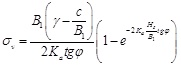
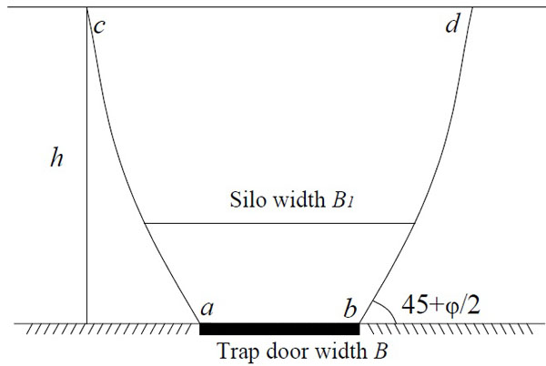
A trapdoor experiment was conducted to investigate the soil pressure in the arching theory as shown in Fig. (1), based on which the original model of Terzaghi soil arching was proposed. The shearing resistance along the contact zone (sliding surfaces ac and bd) between the yielding and the stationary soil will develop, which is against the relative movement of the soil when the trapdoor moves downwards. The pressure acting on the trapdoor is reduced when the yielding soil also move down with the trapdoor since the shearing resistance mobilized against the downward movement of the sliding wedge along the surfaces tends to keep the yielding mass in its original position. This pressure reduction due to shearing resistance is generally known as soil arching effect. The two sliding surfaces rise at an angle of 45+ φ/2 degrees from the outer edges of the trapdoor and end at an angle of 90 degree when reaching the surface [11, 12]. With the only consideration of the soil loads, the Terzaghi soil arching formula can be deduced as Equation 1.
 |
(1) |
where σ is the earth pressure on trapdoor (kN/m2); γ is the soil average effective unit weight
(kN/m3); H is the depth of cover (m); c is the soil cohesion (kN/m2); φ is the angle of wall friction (°); and B1 is the calculating width (m).
3. DIFFERENT STANDARDS FOR CALCULATING SOIL PRESSURE ON TRENCHLESS PIPELINESS
3.1. GB Standard
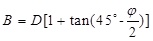
The Chinese national standard GB50332 [3] has defined the calculating method of soil pressure installed by trenchless technologies based on Terzaghi soil arching theory, and the related parameters have been simplified. The friction angle φ mobilized in the sliding surfaces is assumed to be 30°. The product of active earth pressure coefficient Ka and the friction coefficient of the sliding surfaces μ is simplified to be 0.19 for general soil based on experience. For a drilling hole with diameter D, buried depth h, the calculating width B can be obtained by Equation 2, and the soil arching factor κ and soil pressure q can be calculated by Equations 3 and 4 below.
 |
(2) |
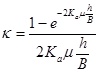 |
(3) |
 |
(4) |
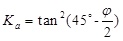
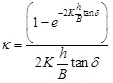
3.2. ASTM Standard
For HDD applications, a modified version of Equation 1 (Terzaghi’s model) is proposed in ASTM F 1962 [4] used in North America. The cohesion strength of soils is totally disregarded, the friction angle δ mobilized in the sliding surfaces is assumed to be half of the friction angle (φ/2) of the in situ soil, and the silo width B is defined as 1.5D.The active earth pressure coefficient Ka is calculated by Equation 5, and the ASTM F 1962 arching factor κ is presented in the following Equation 6. A minimum required cover depth h of the pipe is 5 times of pipe diameter D in ASTM F 1962 standard since it can guarantee the development of the soil arching.
 |
(5) |
 |
(6) |
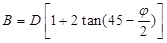
3.3. EN Standard
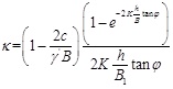
The EN 1594 standard [5] uses two different methods for calculating the soil earth pressure acting on trenchless pipelines, respectively in granular and compressible soils since the arching degree in two groups of soils is obviously different. A minimum required cover depth h of the pipe is 4 times of silo width B for both the two types of soils in EN standard. For granular soils, such as sand soil, a better arching effect is formed, while in compressible soils, the consolidation effect tends to diminish the arching effect. For granular soil, the cohesion strength c of the soil is considered, the lateral soil pressure coefficient K is thought to be the static earth pressure coefficient calculated by Equation 7 and the silo width B is calculated by Equation 8. The EN arching factor κ is presented in the following Equation 9.
 |
(7) |
 |
(8) |
 |
(9) |
 |
(10) |
For compressible soils, the arching mechanism is different from granular soils. Meijers and De Kock [13] explained the background of the EN standard’s calculation method for clays. The Terzaghi’s theories of arching and consolidation are incorporated to recommend a new set of equations for calculating the arching factor in compressible soils [12]. Firstly, the soil pressure q is calculated using Equations 7-10, and the maximum shear forces Fmax is calculated by Equation 11, then the reduced shear force due to the consolidation effect, Fr is calculated by Equation 12, finally, the arching factor is acquired by Equation 13.
 |
(11) |
 |
(12) |
 |
(13) |
The arching models in all of the three standards discussed in the previous sections originated from Terzaghi’s soil arching theory, but different modifications have been applied to basic parameters, such as the wall friction angle, coefficient of lateral earth pressure, and silo width. The calculation parameter in three standards has been summarized and compared in the following Table 1.
| GB 50332 | ASTM F1962 | EN 1594 | ||
|---|---|---|---|---|
| Properties of soils | Non-classified | Non-classified | uncompressible | compressible |
| Minimum depth h/m | Un-defiend | >5D | >4B, or little less than 4B | |
| Friction angle φ of the sliding surfaces/° | φ=30 | δ = φ/2 | δ = φ | |
| Product of K and μ | 0.19 | |||
| Silo width B/m | ||||
4. PARAMETER COMPARISONS AMONG EACH STANDARD
4.1. Product of Lateral Soil Pressure Coefficient K and the Friction Coefficient of Sliding Surface μ
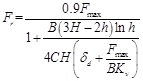
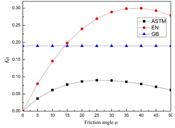
In Terzaghi model, the mobilized shear force along the 2 sliding surfaces partially bear the soil load. The lateral soil pressure coefficient K is a ratio of the lateral soil pressure to vertical soil pressure, and the friction coefficient of sliding surface μ is the tangent value of the friction angle of the soil. The product of lateral soil pressure coefficient K and the friction coefficient of sliding surface μ have an leading influence on the shear force. Thus the values of Kμ is first of all studied in each standard. The comparison has been made in Fig. (2). It is shown that as the friction angle increases, the value of Kμ in both ASTM and EN standard firstly increase and then decrease, while Kμ keeps at a constant value of 0.19. The maximum value Kμ in the former two standards is 0.09 and 0.30, respectively. When φ <15°, the value in GB standard is the maximum, and when φ > 15°, the value in GB standard is the maximum among three standards. The value Kμ represents the mobilized shear strength of the sliding surfaces between the settled soil and the in situ soil. As the shear strength becomes higher, the soil load acting on the pipeline crown is smaller, which means a better soil arching effect. The conclusion can be made that there is a great discrepancy on the effect of friction angle on the value Kμ in each standard.
4.2. Silo Width B
Typically, the silo width depends on the soil friction angle and the pipe diameter. Many researchers have defined the shear plane positions and the silo width B [6, 8]. One of the most popularly used formula determining the silo width is the Equation 8. Fig. (3) presents the variation of silo width B normalized to pipe Diameter D with respect to the soil friction angle for each standard. Fig. (3) shows the variation of the ratio B/D with respect to soil friction angle φ for each standard. For a safe design ASTM standard recommends the largest ratio B/D to be a constant of 1.5 which is, however the smallest among three standards. For EN and GB standard, an almost linear relationship can be seen that the ratio B/D decreases from 3.0 to 1.7 and 2.0 to 1.3 respectively, with an increase in soil friction angle from 0 to 50 degrees. For all friction angles, the EN Standard is the largest one. The conclusion can be made that there is still a great discrepancy of the silo width B in each standard.
5. THE SOIL ARCHING FACTOR FOR GRANULAR SOILS
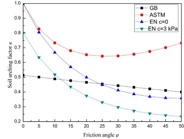
The influence of friction angle on the soil arching factor in granular soils is studied according to a calculation sample. Assuming that a 1.0 m diameter pipeline installed under 8 m cover depth in granular soils of 20 kN/m3 weight, the relationship of the soil arching factor with respect to the friction angle is shown in Fig. (4).
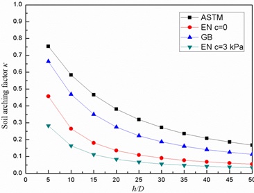
All of the standards show an obvious decrease of the soil arching factor as the friction angle φ increases, except a slight increase after the value of φ reaches to 30 degrees in ASTM standard. Generally, The GB and ASTM standards do not consider the effect of the cohesion of soil. The soil arching factor in ASTM standard is largest for all friction angles, and the arching factor firstly increases then decreases as the friction angle increases. There is a minimum value of 0.64 in ASTM standard when the friction angle is nearly 30 degrees. However, for EN standard with c = 0, there is a continuous decrease as the friction angle increases. And a 3 kPa cohesion strength, the EN standard will lead to a nearly 20% reduction of the soil arching factor, which means that cohesion plays a leading role in soil arching effect. The GB standard soil arching factor was the smallest, when the soil friction angle is less than 15 degrees. It can be explained that the simplification of the parameter Kμ equalling to 0.19 seem to be unsafe for soils with smaller friction angles, since for soil friction angle less than 15 degrees, Kμ in GB standard is obviously much larger than that in other 2 standards, which has been shown in Fig. (2) . To figure out the impact of the ratio of the cover depth h and silo width B on the soil arching factor, Fig. (5) plots the variation of the soil arching factor to h/D in granular soils with friction angle φ = 30 degrees and cohesion strength c = 0.
Fig. (5) presents that, for a cohesionless granular soil of 30° friction angel, the soil arching factor κ of ASTM and EN standard is correspondingly the largest and smallest for all ratios of h/D angles, which shows a consistency with the results shown in Fig. (4). All of the soils arching factor decrease as the ratio h/D increases, which means a deeper cover of the soil contributes much to the arching effect. The soil arching factor keeps decreasing as the ratio h/D increases. For EN soil arching factor, 3 kPa cohesion strength leads to a 40% reduction. It can be inferred that for enough cover depth, the arching factor will be zero which means there is no soil load on the pipeline.
6. THE SOIL ARCHING FACTOR FOR CLAY SOILS
Even though initially Terzaghi derived the soil arching theory for sand soils, GB and ASTM standards modified the equation for use with both granular and compressible soils. During modifications, the effect of cohesion has been ignored totally in both the standards. In soil mechanics, it indicates that for over-consolidated clays, both friction angle and cohesion terms are significant. Negligence of cohesion in OC clays will result in an overestimation of the soil arching factor and reduction of the arching effect. EN considers the impact of consolidation effect of clay soils on the arching effect and uses a revised equation to calculate the clay soil arching factor with Equations 11-13. Fig. (6) shows the relationship of arching factors from GB, ASTM and EN Standard models with respect to the soil friction angle for a 1 m diameter pipe, installed in a 8 m deep covered clay soil. The thickness of compressible layer H and the cohesion c is assumed to be 6 m and 3 kPa, respectively. The related parameters KV, δd, and C were empirically selected as 500 kN/m3, 0.01 m, and 6.0, respectively according to Meijers and De Kock [13].
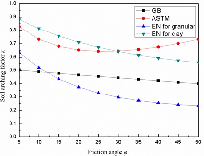
As Fig. (6) shows, all of the standards show a decrease in κ as the friction angle increases except a slight increase in ASTM when the friction angle is larger than 25 degrees. There is a great discrepancy between the arching factors based on the two methods for granular and clayey soils in EN standard. It is revealed that, the soil arching factor is much greater depending on the method for clay soils and granular soils. For clayey soils of friction angle less than 30 degrees, the EN standard formulation for clay predicted a greater arching factor, and therefore greater earth pressure. Overall, the discrepancy is not much for all friction angles. The results from the method in GB standard are the smallest when applied in clayey soil. It indicates that the method for granular soil in EN standard and GB standard may lead to an overestimation of the arching effect of clayey soils. The results from ASTM method show a small error fluctuation with the EN method for clayey soils; However, it needs to be further validated with field measurements.
CONCLUSION
This paper introduced the calculating methods, comparing key parameters for soil pressure and focused on the differences among the three standards which have been widely used in North America, Europe and China. The comparison of soil pressure calculating methods in both granular and clay soils based on the Terzaghi model have been made. Based on the investigation, conclusions can be made as follows:
- The soil arching models in all of the three standards originating from Terzaghi’s soil arching theory discussed in the previous have variously modified basic parameters such as the wall friction angle, coefficient of lateral earth pressure, and silo width, which have significant influences on the soil arching factor. There are great discrepancies on the effect of friction angle on the values Kμ and silo width B in each standard.
- The GB and ASTM standards disregard the cohesion strength and utilize the same method to calculate arching factor for all soil types, including granular soil and clayey soil, while the EN standard takes the influence of cohesion strength into account and applies two different methods respectively for calculating arching factors for granular and clayey soils.
- For granular soil, the soil arching factor in all of the standards show an obvious decrease as the friction angle φ The friction angle increases except light decrease after the value of φ reaches to 30 degrees in ASTM standard, which does not accord with the Terzaghi arching theory. The soil arching factor in ASTM standard is largest for all friction angles, while the soil arching factor from GB standard was the smallest, when the soil friction angle is less than 15 degrees. The simplification of the parameter Kμ equalling to 0.19 seem to be unsafe for soils with smaller friction angles, since for soil friction angle less than 15 degrees, Kμ in GB standard is obviously much larger than that in other 2 standards. Comparing with the soil arching factors for soils with 0 and 3 kPa cohesion, it can be seen that the cohesion plays an important role in soil arching effect for EN standard, while it is not considered in other two standards.
- As the ratio h/D increases, arching factors of granular soil in each standard decreases, which means a deeper cover of the soil will contribute to arching effect. It can be inferred that for enough cover depth, the arching factor will be zero.
- For clayey soils, the soil arching factor is much greater depending on the method for clay soils than that for granular soils in EN standard. For clayey soils with φ less than 30 degrees, the EN standard formulation for clay predicted a greater arching factor, and therefore greater earth pressure. The results show that the method for granular soil in EN standard and GB standard may lead to an overestimation of the arching effect of clayey soils.
CONFLICT OF INTEREST
The authors confirm that this article content has no conflict of interest.
ACKNOWLEDGEMENTS
Declared None.

