All published articles of this journal are available on ScienceDirect.

The Elastic Critical Load of Single Angle Columns
Abstract
The design of single angle columns requires the ability to predict their flexural-torsional buckling strengths and flexural buckling strengths about the minor principal axis. Present design code provisions are quite different. This paper presents close approximations for the elastic critical load of equal angle section columns. It is found that the member capacities are less than the minor axis capacity at low slenderness and almost remain constant. A formula of the balance point is proposed which is simpler and better understanding.
1. INTRODUCTION
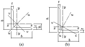
Single angles in compression are widely used in steel structural members. Single angle section may be equal-leg or unequal-leg, as shown in Fig. (1). The geometric axes parallel to each leg are x-axis and y-axis separately. The principal axes are u-axis and v-axis (the v-axis is also called the minor principal axis). It should be noted that, in the following, we will focus our research on the case of equal-leg angles.
For a centrally compressed member, overall buckling or local buckling may occur. The overall buckling has three modes: flexural buckling, torsional buckling and flexural-torsional buckling. For a centrally compressed member with an equal-leg angle, not only flexural buckling about axis v may occur, but also flexural-torsional buckling about axis u may occur. However, several design codes have different treatments.
According to AISC code Load and Resistance Factor Design Specification for Single-Angle Members, it is unnecessary to consider flexural-torsional buckling under the situation of calculating the member capacity of single angle columns [1]. Generally speaking, flexural buckling about v-axis is enough. It is interesting that similar conclusion has also been drawn by ANSI/AISC360-2005 [2]. In ANSI/AISC360-2010 this provision has been changed that flexural-torsional buckling should be considered for single angles with b / t > 20 [3]. In fact, this applies to only fabricated angles because all hot rolled angles currently produced have b / t < 20.
In European code EN1993-1-1:2005, for angle sections, accounting should be taken of the possibility that the critical load of flexural-torsional buckling could be less than flexural buckling [4]. In other words, flexural-torsional buckling force should be used to determine the non-dimensional slenderness.
In China, Prior to Code for design of steel structures (GB50017-2003), the design capacity of axially compressed single angles is based on flexural buckling of minor principal axis, and buckling curve b is adopted. However, in GB50017-2003, the equivalent slenderness ratio is required if single angle columns bend about u-axis, which is derived from flexural-torsional buckling capacity [5].
In this paper, based on elastic stability theory and cross-section characteristic of single angles, a simplified formula about the balance point of flexural-torsional buckling capacity and flexural buckling capacity was proposed. When the length of column is less than the balance point, the elastic critical load can be calculated conservatively by flexural buckling formula at this point.
2. ELASTIC FLEXURAL-TORSIONAL BUCKLING CRITICAL LOAD OF SINGLE ANGLE COLUMNS
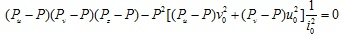
For an axial compression member with pinned ends, in the case of single angle, the elastic critical load is the lowest root of the equation as follows [6]:
 |
(1) |
 |
(2) |
 |
(3) |
 |
(4) |
 |
(5) |
where
| Pu, Pv | = | elastic critical loads for flexural buckling about principal axes |
| Pz | = | elastic critical load for torsional buckling about z-axis |
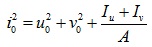
| i0 | = | polar radius of gyration about the shear center |
| u0, v0 | = | coordinates of the shear center with respect to the centroid |
| E, G | = | elastic modulus and shear modulus of steel |
| J | = | torsional constant |
| Iu, Iv | = | moment of inertia about the principal axes |
| L | = | length of the compression member |
| A | = | cross section area |
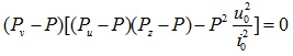
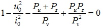
If the section is an equal leg angle, v0 = 0, the Eq. (1) reduces to
 |
(6) |
The three roots for this equation are given as follows.
 |
(7a) |
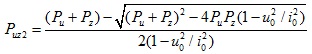 |
(7b) |
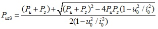 |
(7c) |
Due to Puz3 ≥ Puz2, the critical load is the minimum value of Puz1 and Puz2, or, written as min (Pv, Puz). In other words, we can say that the compression member would undergo flexural buckling about v-axis or flexural-torsional buckling.
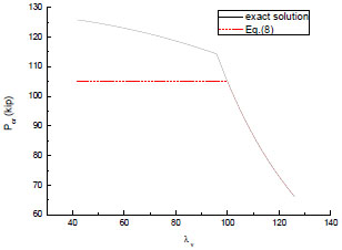
A serial hot rolled equal angles was given by Steel Construction Manual (14th edition) [7], in which the section ∟4×4×3/4 has the minimal width-to-thickness ratio(equals to 19.2) and ∟6×6×5/16 has the maximal(equals to 5.3). Using the section properties from this book and adopting E=29000ksi and G=11200ksi, we can plot the elastic critical load Per in Fig. (2). If the horizontal coordinates of point A in Fig. (2) is defined as Ld, then we can say that flexural-torsional buckling will happen when the member length is less than Ld. Moreover, the critical load decreases slowly within this range. As for section ∟6×6×5/16, the critical load drops about only 9.0% when the column length changes from 50 in. to 114 in.
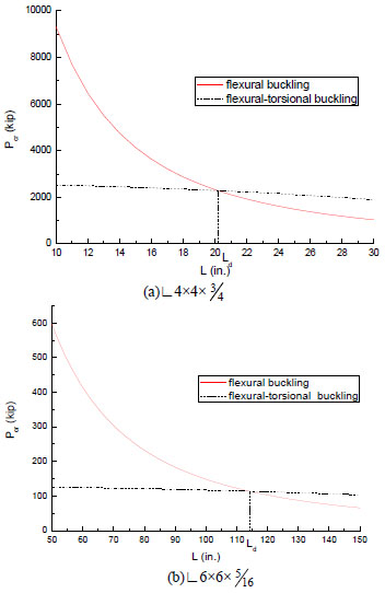
Thus, an approximate and conservative expression can be obtained as follows.
For L ≤ Ld
 |
(8a) |
For L > Ld
 |
(8b) |
3. THE BALANCE POINT OF FLEXURAL BUCKLING AND FLEXURAL- TORSIONAL BUCKLING
When Eq.(7b) equals to Eq.(7a), we obtain
 |
(9) |
Substituting Eq.(2) to Eq.(4) into Eq.(9) leads to
 |
(10) |
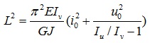
So the balance point of flexural-torsional buckling and flexural buckling is
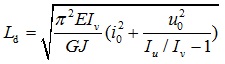 |
(11) |
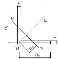
In fact, we can derive a clearer expression of Ld with a simple model.
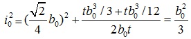
Using two rectangular areas represent two legs of single angle, as shown in Fig. (3), we can obtain the cross-section characteristic as follows.
 |
(12) |
 |
(13) |
 |
(14) |
 |
(15) |
 |
(16) |
in which b0 is the center-to-center length of a leg segment, t is the thickness of a leg.
Substituting Eq.(12) to Eq.(16) into Eq.(11), meanwhile E=29000ksi and G=11200ksi, leads to
 |
(17) |
4. COMPARISION TO THE EXACT SOLUTION
To check the validity of Eq.(17), total 51 equal angles are selected from Steel Construction Manual(14th edition). The values of Ld are obtained by Eq.(11) and Eq.(17) separately and the results are shown in Fig. (4). It is worth noting that the horizontal coordinates are the index number of 51 equal angles arranged as the order in that book. Data indicate that the error range is -5.3% to 9.6%.
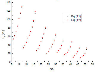
Table 1 shows all the errors above 5% in the approximate expression. The notation LdEand LdAare the balance point obtained by exact solution and Eq.(17) respectively. λv, d = LdE/ iv is the slenderness ratio about v-axis and the column length is LdE. iv is the radius of gyration about the v-axis.
| Angle size |
LdE (in.) |
LdA (in.) |
Error (%) |
λv, d |
|---|---|---|---|---|
| 4 × 4 × 3/4 | 20.2 | 19.1 | -5.3 | 22.4 |
| 4 × 4 × 1/4 | 61.7 | 65.5 | 6.2 | 113.5 |
| 3 × 3 × 3/16 | 46.7 | 49.1 | 5.1 | 132.4 |
| 21/2 × 21/2 × 1/2 | 11.7 | 11.0 | -5.3 | 25.5 |
| 21/2 × 21/2 × 3/16 | 31.6 | 33.7 | 6.6 | 109.0 |
| 2 × 2 × 3/16 | 20.1 | 21.1 | 5.2 | 86.0 |
| 2 × 2 × 1/8 | 29.9 | 32.7 | 9.6 | 154.1 |
Since the columns whose slenderness ratios are less than 30 or more than 100 are seldom used in practice, the error in LdAis no longer important for them. Then it can be concluded that Eq.(17) can be used with good accuracy to distinguish two buckling mode in engineering, although this expression is derived from a simplified model.
When Eq.(8) is used to predict the elastic critical load and Ld is obtained by Eq.(17), the results are shown in Fig. (5). The section is ∟6×6×5/16. The horizontal coordinates are λv, the slenderness ratio about v-axis. Data indicate that the capacity is hardly underestimate. The error is -16.6% if λv equals to 40, although the error of Ld is only 4.4%. If the constant 1.09 in Eq.(17) is replaced with 1.05, the error will be within -10%.
CONCLUSION
The stable capacity of single angle columns may be controlled by flexural-torsional buckling or flexural buckling, but the boundary is not so clear. According to a simplified model, an approximate expression of dividing point, the specified column length Ld, has been provide. The elastic critical load will be calculated by flexural buckling instead of flexural-torsional buckling in the range of Ld. Moreover, since formula of Ld involves only two parameters of an angle section, engineers will find it to be easy to understand.
NOTATIONS
The following symbols are used in this paper:
| A | = cross section area of member |
| b | = full width of a leg |
| b0 | = width of a leg referring to midlines, equal to b – t / 2 |
| E | = elastic modulus of steel = 29000 ksi |
| G | = elastic shear modulus of steel = 11200 ksi |
| Iu, Iv | = moments of inertia about u-axis and v-axis |
| i0 | = polar radius of gyration about the shear center |
| iv | = radius of gyration about v-axis |
| J | = torsional constant |
| L | = length of compressive member |
| Ld | = balance point of flexural-torsional buckling and flexural buckling |
| LdE | = exact solution of |
| LdA | = approximate solution of |
| Pu, Pv | = elastic critical loads for flexural buckling about u-axis and v-axis |
| Pz | = elastic critical load for torsional buckling about v-axis |
| Puz1, Puz2, Puz3 | = three roots obtained from cubic equation |
| t | = thickness of leg |
| u0, v0 | = coordinates of the shear center with respect to the centroid |
| λv, d | = slenderness ratio about v-axis |
CONFLICT OF INTEREST
The authors confirm that this article content has no conflict of interest.
ACKNOWLEDGEMENTS
The authors deeply appreciate the generous support of the National Natural Science Foundation of China (No. 51278010) and the Beijing Natural Science Foundation (No. 13H10089).

