All published articles of this journal are available on ScienceDirect.
Study on Mechanical Properties of Concrete Filled Square Steel Tubular Column Joints
Abstract
A new type of connection node filled with steel tubular column is proposed for the frame structure of concrete. In this paper, the mechanical properties and failure mechanism are studied. As shown by the finite element analysis results, the hysteresis curve attains the full standard, indicating that the joints possess good deformation performance, as well as good bearing capacity, ductility and energy dissipation capacity. Based on the results of the finite element analysis, the experimental study of this type of node is carried out. Meanwhile, a series of experiments are conducted to enhance the length of the steel plate, the effectiveness of the steel plate and the thickness of the protective layer of the steel plate.
1. INTRODUCTION
Square steel tube concrete column possesses good bending, shearing capacity, energy dissipation capacity and perfect shape rules, which will be conducive to the connection of beam column and the construction design. Moreover, it has good development and application prospects. Many researches, which focus on the performance and design methods of the concrete filled steel tubular column, have been done. However, the research of the concrete filled steel tube concrete column and reinforced concrete beam joint is seldom studied [1-3]. Even though the force of connection from of existing concrete filled square steel tubular column and beam are clear and reliable, there is a large amount of field welding required. It can make the pipe hole increase, affecting the filled steel tubular column tube concrete pouring [4-7]. Currently, it is essential to develop new connection through the slotted steel plate concrete beam - column connection joints - square steel reinforced concrete structure concrete beam column frame structure. In this paper, the finite element model of the joints is analyzed through the finite element analysis ANSYS software. Also, a detailed analysis is made on the key node. Additionally, the component and part of the rule of stress and strain development is obtained and the feasibility of this new type of joint is implemented.
2. NEW SQUARE STEEL TUBULAR COLUMN JOINTS
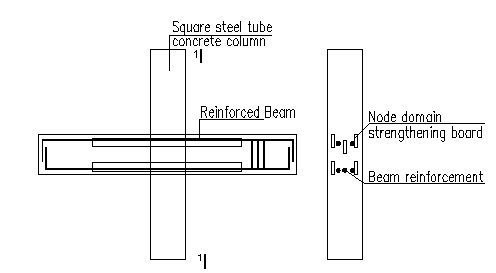
Node design and construction practices can be shown as follows. To ensure the bond force between steel plate and concrete effectiveness in plate slotted, the thickness of the steel plate is relatively small. In this way, it can not only guarantee the node domain of steel pipe internal voids, but also ensure the quality of the concrete in the steel tube internal node in the core area.
The frame beam end part of the longitudinal ribs is welded on the pipe wall. Meanwhile, part of the longitudinal reinforcement is through the tube and across the beam longitudinal reinforcement connection. As displayed in Fig. (1), two parts of longitudinal reinforcement and wear tube plate together are set to resist the bending moment at the end of the beam and improve the integrity of the node.
3. FINITE ELEMENT ANALYSIS OF A NEW TYPE OF CONCRETE FILLED SQUARE STEEL TUBULAR COLUMN JOINT
3.1. Finite Element Model
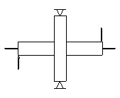
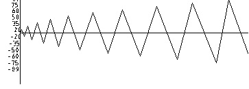
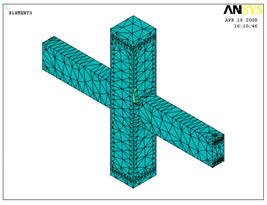
It is a difficult thing to set up three-dimensional model and simulate boundary conditions.This paper puts forward the boundary conditions for the simulation. The only constraint on the plane of symmetry cylinder is on the two end nodes of the x-y-z, three displacement methods to the simulated column hinged below, can be seen by the Saint Venant principle. Thus, the simulation boundary conditions only influence the end range of smaller stress distribution, and there is no need to study the node stress that has no effect on the distribution. The specific constraints can be shown in Fig. (2). Beam end loading mode can be shown in Fig. (3).
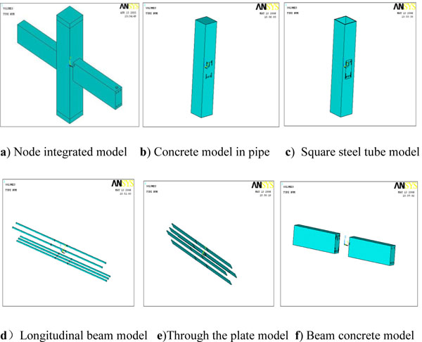
To simulate the force of each component of the node in a better way, the node components are modeled with solid elements. The steel pipe and piercing steel plate are reinforced by the solid 45 unit, and the concrete element is also solid 65. X-shaped loading scheme is put forward in this paper. For determining the availability of the test device, the model is analyzed through finite element simulation [8-10] shown in Figs. (4 and 5).
3.2. Interpretation of Result
3.2.1. Stress Analysis of Reinforced Concrete Beam
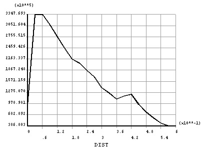
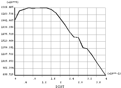
Obviously, the stress peak value appears at the edge of the steel tube (Figs. 6 and 7), which can be clearly seen from the beam length direction stress curve (Fig. 8). In the end of piercing steel plate, reinforced stress has a mutation phenomenon. However, the changed value is not significant. In fact, with piercing steel plate to the anchorage length, force borne by the steel and the bending moment is not here, were not observed, determining that the stress value of the mutation is not significant, which can be seen from the stress variation curve (Fig. 8) along the length of the steel pipe. The shape of the whole curve is parabolic, yet it is not symmetrical to the center of the column. The main reason is that, there is no axial force in the end of column, but also large axial force in the end of beam.
Steel bars on one side of the beam are cut off from the edge of the steel pipe column. According to the finding, the reinforced maximum value was not shown in steel pipe connection, but found to be closed to the steel pipe column (Fig. 9). As shown, due to the fact that the existence of piercing steel plate makes nodes in the domain of large stiffness, failure did not occur in the core area of the node domain and piercing steel plate in the presence of the plastic hinge shift. Hence, it is essential to better see the mutation at the end of the bar close to the piercing steel plate obviously.
3.2.2. The Stress Analysis of Steel Plate
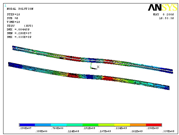
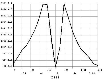
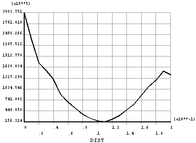
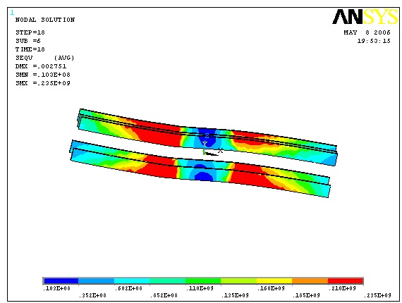
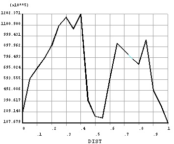
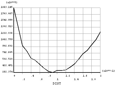
Stress cloud chart is show in Fig. (10), and piercing steel plate along the length direction of the Mises force curve is displayed in Fig. (11). It can be seen that the maximum piercing steel plate does not appear at the edge of the pipe wall, but gets close to the edge of the steel pipe column. The reason is that beam piercing steel plate makes the nodes in the domain of plastic hinge shift from piercing steel plate Mises. Pipe piercing steel plate stress cloud chart along the length direction of the Mises stress curves revealed that the force distribution and reinforced stress distribution are consistent (Figs. 12 and 13).
3.2.3. Hysteresis Curve of a Node
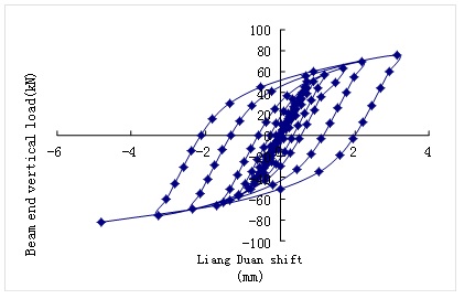
The node finite element calculation structure finally obtained hysteresis curve can be shown in Fig. (14) Moreover, the hysteresis curve is full, which has a very typical spindle shape, indicating that this model of energy dissipation and deformation capacity is quite good. Also, this curve shows that the maximum displacement of the beam end is 4.8mm, because the Ansys analysis does not consider the bond slip problems of concrete, which is a gap with the actual situation of work and experiment. To guarantee that the steel plate can play its role in the steel plate,the steel plate with sufficient protective layer thickness shall be set up to increase the steel plate and concrete bite force.
3.2.4. Skeleton Curve of Node
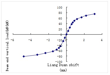
According to the finite element analysis, the skeleton curve of the load and the displacement of the load on the specimen can be shown in Fig. (15). The skeleton curve is the maximum peak value of the load deformation curve of each cycle. Under normal circumstances, the skeleton curves are composed by third and fifth load vertices. The load displacement curve is quite similar to that of the skeleton curve and the monotonic loading. However, the limit load is slightly lower than that of the monotonic loading. Furthermore, skeleton curves can be utilized to qualitatively compare and measure the seismic behaviors of structural members.
CONCLUSION
The following conclusion can be drawn from the experiment and the finite element analysis:
- Compared with the experiment of making simple and good mechanical properties of the steel to be utilized less, piercing steel plate nodes and regular node can ensure node domain concrete pouring and tamping quality. Moreover, the bearing capacity and mechanical properties are improved to a great extent.
- Feedthrough between steel plate and concrete bonding force plays a quite significant role. In the actual use, it should be in the plate groove, and ensuring that the plate has adequate protection layer thickness to increase the bite force of steel and concrete.
- As shown by the finite element analysis results, the hysteresis curve attains the full standard, revealing that the joints have good deformation performance, good bearing capacity, ductility as well as energy dissipation capacity.
- According to the results of the finite element analysis, the experimental study of this type of node is conducted later. Meanwhile, a series of experiments are carried out to enhance the length of the steel plate, the effectiveness of the steel plate and the thickness of the protective layer of the steel plate.
CONFLICT OF INTEREST
The authors confirm that this article content has no conflict of interest.
ACKONWLEDGEMENTS
The author wishes to express his gratitude to Natural Science Foundation of Fujian Province (2015J01183), Fujian Provincial Department of education JK project (JK2014060) and Fujian Jiangxia University project (JXZ2014002) for the financial support to the research group. Also, the writer would like to thank the anonymous reviewers for their insightful comments and suggestions that have improved the content of this paper.


