All published articles of this journal are available on ScienceDirect.
Finite Element Modeling and Mechanical Behavior of Masonry-Infilled RC Frame
Abstract
During the analysis of reinforced concrete structures, the infill wall is usually simplified as a diagonal inclined strut to facilitate finite element modeling calculations. However, the actual seismic damage and single frame-filled wall pushover experimental results show that when the earthquake shear force is huge, the top of the infill wall and the beam–column connections are usually, thus the path of the force transfer will be changed. Based on this actual failure phenomenon, a new calculation model which has different contact position between the equivalent bracing walls and the frame columns is generated. Thus, the force analysis is given based on this model, the formulae for calculating the equivalent width of bracing walls, the shear bearing capacity of the wall-filled frame, and the infill wall’s actual participation in the stiffness. A finite element simulation method by ABAQUS is used to determine an empirical formula for calculating the reasonable contact position between the equivalent bracing walls and the frame columns. The verification results show that the finite element model presented in this paper is more reasonable, and the stiffness and shear resistance of infill wall should not be neglected. The calculation formula of stiffness of infill wall presented in this paper is coincided with seismic code. But the calculation formula of shear resistance of infill wall presented in seismic code is higher than the actual value, so it is suggested that calculation formula presented in this paper should be accepted.
INTRODUCTION
Reinforced concrete frame filled wall structure is one of the most widely used structural forms in China. In recent years, the seismic damage caused by the interaction between the infill and the frame is very serious [1]. In order to study the failure mechanism of the infill frame structure, the finite element model is established for numerical simulation. In the field of earthquake engineering, the infilled wall is usually simplified as equivalent diagonal strut which is based on certain assumptions. The concept of an equivalent diagonal strut was first proposed by Polyakov [2] based on experimental results, where he considered that the infill wall can be simplified as diagonal bracing walls with compression but no tension. Based on this theory, the macro modeling approach got greatly developed since it constituted the most attractive technique to perform complex nonlinear analyses [3]. El-Dakhakhni [4] replaced infill by three struts with force-deformation characteristics based on the orthotropic behavior of the masonry infill. A simplified steel frame model was presented which could be easily computerized. Chrysostomou[5] idealized infill with six compression only inclined struts, which followed the behavior defined by the strength envelope and hysteretic loop equations. The advantages of this analytical model were that both strength and stiffness degradation of infill walls were modeled and the off-diagonal struts allowed modeling of the interaction between the infill and the bounding frame. The above improved multi-strut diagonal bracing model can be readily adapted to fit the actual data, but it is not easy to be applied to the overall model during large scale computations.
In addition to the complexity of the stress between the infill wall and the frame, the local shear action caught the attention of researchers. Asteris [6] found that the shear forces acting on columns are considerably higher than those obtained from the analysis of the bare frame especially in a soft ground story. Cavaleri [7] considered that the additional shear forces arising at the ends of beams and columns might lead to the activation of brittle collapse mechanisms, and supported a simplified model which is adopted consisting in the substitution of infill with an equivalent pin jointed concentric strut. According to earthquake damage in recent years, it is common that the brick masonry between the top of the infill wall and the corner of the beam–column joint is usually crushed under the local shear action (Fig. 1); thus, in the ultimate bearing capacity conditions, the equivalent diagonal strut model of the rod end supported on the beam–column joint is not reasonable. The reasonable contact position between the diagonal brace wall and the frame column also needs to be studied further.
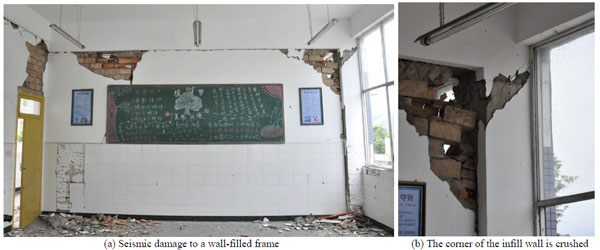
Damage caused to Shangli middle school in Yucheng during the Lushan earthquake.
Based on previous research into the infill wall status, as outlined above, this article focuses on the force analysis, and derives the formulae for calculating the stiffness, shear strength, and width of the equivalent bracing wall in the ultimate bearing capacity conditions, thereby providing a reference for seismic damage analysis and structure design. Using the finite element software ABAQUS, the single wall-filled frame component is simulated and used the formula to fit the results, thereby obtaining an empirical formula related to the reasonable contact position of the equivalent diagonal strut and frame column, and present a new equivalent diagonal single-strut bracing model of a wall-filled frame component.
1. Derivation of the theoretical calculation formula
1.1. Calculation Diagram and Basic Hypothesis
The calculation diagram for single frame-filled wall components is shown in Fig. (2), which assumes that only bracing walls with a certain width participate in the force under the seismic load, where the contact length with the frame column is denoted as αch, the bracing wall thickness t is the same as the infill thickness t, and the sloping angle between the medial axis of the equivalent diagonal bracing wall and the horizontal direction is denoted as θ'. The following basic hypothesis is proposed based on the model. First, it is considered that the infill walls are made of ideal homogeneous isotropic materials. Second, for convenience, it is assumed that the border of the infill coincides with the central axis line of the frame in the following force analysis, i.e., h' = h, l' = l, where h' and l' are the height and span of the frame, respectively, h and l are the height and span of the infill. Third, the simplified brace infill wall has no contact with the beam. There is a certain distance Δx between the top of the bracing walls and the frame beam, and the contact length with the frame column may not exceed 0.3 times the height of the infill, as shown in Eq. (1). Fourth, according to the nonlinear finite element analysis results provided by Saneinejad [8] in 1990, the ratio of the maximum elastic moment and the plastic yield moment in the columns and beams may not exceed 0.2, as shown in Eq. (2):
 |
(1) |
 |
(2) |
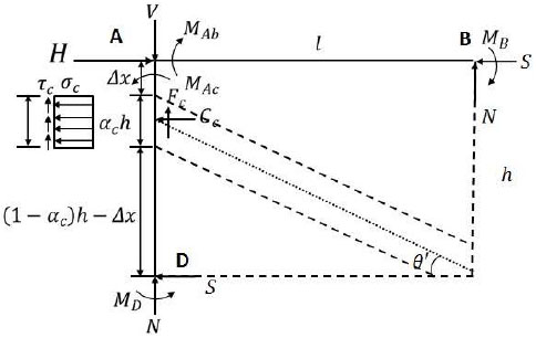
Simplified calculation model and forces in the wall-filled frame.
where αc is the normalized length of contact of the frame column, Mc and Mb are the maximum elastic moments in the columns and beams, respectively, Mpc and Mpb are the plastic yield moments in the columns and beams, βc and βb are the ratios of the maximum elastic moments and plastic yield moments in the columns and beams, and β0 is the upper-bound value of the ratio of the maximum elastic moment and plastic yield moment in the columns and beams.
1.2. Computation of the Shear Strength
Taking the frame column on the left hand side and the frame beam on the top as an isolated body, as shown in Fig. (3):
 |
(3) |
 |
(4) |
where H is the horizontal bearing capacity of shear, Cc is the normal force at the column–infill interface, S is the column shear force and beam axial force at the unloaded corners, σc is the proposed uniform normal stress at the column–infill interface, and t is the infill thickness.
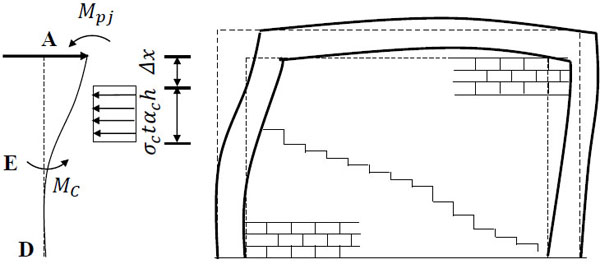
Forced distortion diagram of a wall-filled frame.
In Fig. (3), taking the bending moment of point A through the internal force of frame column AD according to ΣMA = 0, and S can be expressed as:
 |
(5) |
Where Mj represents the bending moments of points B and D in the infill corner. To simplify the analysis, it is considered that points B and D have equal bending moments, i.e., MB = MD = Mj, where the value of Mj is very small in the load that influences the collapse failure of the infill wall and thus it can be neglected if necessary.
Substituting Eq. (4) and (5) into Eq. (3) yields the formula for calculating the shear bearing capacity of the wall-filled frame component H:
 |
(6) |
Where the first part of Eq. (6) is the shear strength of infill wall and the second part represents the shear strength of the bare frame. If R is considered to be the shear strength of the central axis of the equivalent diagonal bracing wall, then Eq. (6) can be rewritten as follows.
 |
(7) |
Therefore, the formula for calculating the specified crushing load of the diagonal strut in CC mode is as follows.
 |
(8) |
1.3. Equivalent Contact Length
At the peak load, the diagonal bracing wall is subjected to failure, which results from the combined normal and shear stresses that act on the surfaces in contact with the frame column. According to Tresca [9], the hexagonal yield criterion is:
 |
(9) |
 |
(10) |
where σ and τ are the proposed uniform normal and shear stresses of the column–infill interface, respectively, r is the height-span ratio of the frame (r = h'/l'), and µ is the coefficient of friction for the column–infill interface with a general value of 0.45 [10]. Eq. (9) and Eq. (10) lead to Eq. (11)
 |
(11) |
where σc0 is the proposed nominal value of the contact normal stress of the column–infill interface, fc is the effective compressive strength of infill, which can by calculate as fc = 0.6ϕ f'm, where f'm is the compressive strength of the infill material, and ϕ is the adjustment coefficient with a general value of 0.65 [10].
As shown in Fig. (3), it is assumed that the equivalent diagonal bracing wall and frame column separate at point E under the horizontal load, and the shear stress distributed uniformly on the contact length range is neglected. Taking the static moment of the forces that act on the column along EA gives the following:
 |
(12) |
Where Mc is the maximum elastic moment of the frame column. After substituting Eq. (2) into Eq. (12) and combining with Eq. (1), the equivalent contact length αch is:
 |
(13) |
1.4. Stiffness of the Equivalent Bracing Wall
Under the horizontal load, the deformation of the frame is shown in Fig. (4) as a dotted line. Assuming that the quality and stiffness of the equivalent bracing wall are concentrated in the center line of the wall, according to the definition of the elastic modulus, the secant elastic modulus of the equivalent diagonal strut is:
 |
(14) |
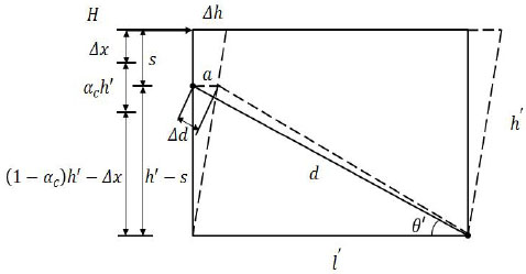
Deflection of the frame.
Where Ed is the secant elastic modulus of the equivalent diagonal strut, εc is the strain on the equivalent diagonal strut due to horizontal load H, d is the length of the equivalent diagonal strut, and Δd is the axial deformation of the equivalent diagonal strut under horizontal load H.
When the frame produces horizontal deflection Δh, the rod end of equivalent diagonal strut has horizontal displacement a. Thus, Eq. (14) can be changed into Eq. (15):
 |
(15) |
 |
(16) |
Where s is the distance between the top of the column and the rod end of the equivalent diagonal strut. It should be noted that the derivation process above occurs in elastic–plastic state conditions, where the wall-filled frame components achieve the ultimate bearing capacity and the initial elastic modulus of the infill wall in the elastic state is higher than the secant elastic modulus of the equivalent diagonal strut. Here it is considered that the initial modulus of elasticity for the equivalent diagonal strut Ed0 is two times larger than the secant elastic modulus Ed:
 |
(17) |
And when Δh = 1, the result calculated for Ed0 is the equivalent diagonal strut stiffness Kd0 , where the stiffness of the horizontal component is the stiffness that the infill contributes to the overall component.
The derivation above gives the method for calculating the shear bearing capacity of the wall-filled frame component and the actual participation of the infill walls in the stiffness, thereby providing a reference for the structure during the design stage of seismic checking. The effective widths of the equivalent bracing walls are given in the form of αch, which provides a method for building the simplified finite element model. When the scantling and material grade of the wall-filled frame component is determined, the relative parameters except Δx are identified. The reasonable value of Δx is determined using the fitting formula method based on the ABAQUS finite element simulation results. In the following, we will introduce the process used to determine the calculation formula Δx and the finite element simulation method.
2. Solid finite element model
2.1. Parameters of Instance Model
Y. S. Tong and G. F. Qian [11] tested a certain number of reinforced concrete frame models to study the bearing capacity and deformation performance of infill frame. In this paper, we take the specimen C-1 and C-3 which included block masonry as examples to construct the solid finite element model with the finite element software ABAQUS and compare the results with the data obtained via testing. Main parameters of the framework model and material properties were as follows: specimens were both single layer with single span, the dimension of column section was 150mm×100mm, the dimension of beam section was 180mm×100mm, column spacing was 1500mm, and story height was 1000mm. The internal force steel of framework used HRB 335, and stirrup used HPB235. Concrete strength grade of C-1 was C20, block shear strength grade was M2.5. Concrete strength grade of C-3 was C30, block shear strength was M5. Other parameters were shown in attached A of literature [11].
2.2. Establishment of Finite Element Model
In ABAQUS, the modeling process was as follows: the frame column, beam, and infill wall used a solid unit (C3D20R), and the steel bar used a truss unit (T3D2). Embedded connections were used in the steel bars of the frame column and beam, and a contact connection was used between the infill and frame column to simulate their interaction. The surface-to-surface contact is one of the interaction types of ABAQUS, the contact property is to define a tangential behavior to simulate interaction between the infill and frame which will separate each other during ultimate bearing capacity. The latest research results show that: this contact method in solid element model could simulate very well. The modeling of the components is shown in (Fig. 5).
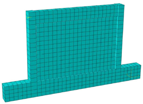
Solid finite element model.
2.3. Constitutive Relationship of Metals
Using ABAQUS's own concrete damage plasticity model to define the nonlinearity of material. In this model, the nonlinear response of the whole structure under earthquake action is simulated by defining the stress-strain relationship of the material under the compression and tensile behavior.
The constitutive relation of concrete is described in literature [12], which gives the uniaxial compression and tensile stress-strain relationship of reinforced concrete members. The stress strain relationship of concrete under uniaxial compression is calculated by the following formulas:
 |
(18) |
 |
(19) |
Where αa and αd are the parameters related to the rise and fall segment of the stress-strain curve of uniaxial compression, fc* is uniaxial compressive strength of concrete, εc is the corresponding peak compression strain of concrete related to fc*.
The following formulae are used for the stress-strain relationship of concrete under uniaxial tension:
 |
(20) |
 |
(21) |
Where αt is the parameter related to the rise and fall segment of the stress-strain curve of uniaxial tension, ft* is uniaxial tensile strength of concrete, εt is the corresponding peak tension strain of concrete related to ft*.
The mechanical properties of masonry materials are more complex than concrete, so the research on the constitutive relation of masonry was proposed by domestic and foreign scholars. In this paper, the masonry constitutive relationship used the research results of C. X. Shi and G. Q. Liu [13] which was based on the results of previous experiments. The rise section is a parabola and the falling section is linear:
 |
(22) |
 |
(23) |
Where fm is the average compressive strength of masonry, εo is the peak pressure strain of masonry.
Damage variable D is used to describe the stiffness degradation of the material in the ABAQUS damage-plasticity model. Damage variable D is also called damage factor, it is a number which is greater than 0 and less than 1. The closer to 1 the value is, the more severe the stiffness degradation is. D is derived based on the assumption that the equivalent of the material energy, and the formulae are as follows:
 |
(24) |
 |
(25) |
Where E0 is the initial elastic modulus, D is damage factor, σ and ε are the stress and strain of materials respectively.
2.4. Comparison of Finite Element Calculation and Test Results
Constructing the solid finite element model of the wall-filled frame component with the finite element software ABAQUS and comparing the results with the data obtained via testing by Y. S. Tong and G. F. Qian. Finally, the load-displacement curves of C-1 and C-3 were obtained using the implicit static analysis method and by applying a lateral load at the beam end. The finite element analysis results and test data are shown in Fig. (6) and (Fig. 7).
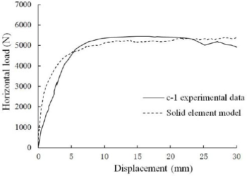
Data comparison of C-1.
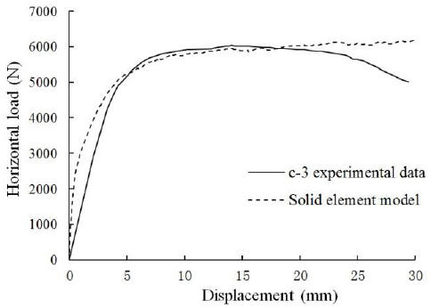
Data comparison of C-3.
Fig. (6) and Fig. (7) compared the finite element simulation values with the solid finite element model based on the load-displacement curves, which both showed that the two curves agreed in the platform segment, thereby demonstrating that the maximum horizontal bearing capacity obtained with the solid finite element model used for the static analysis of the simulation results was close to the actual results. Therefore, the analytical results obtained with the solid finite element model are treated as the actual values for the component in the following process.
3. Equivalent diagonal single-strut bracing model
According to the results in Section 2, the infill can be simplified as equivalent bracing walls, but the reasonable value of the distance Δx between the top of the column and the rod end of the equivalent diagonal strut has not yet been given. Using the finite element simulation, a series of frameworks were designed and by adjusting the value of Δx continuously until the calculation results were consistent with solid finite element model, the reasonable value Δx for each component was obtained. Thus, the empirical formula for the reasonable contact position Δx between the equivalent bracing walls and the frame columns was determined by fitting the formula to all of the results.
3.1. Component Design
Design a series of infill frame components with the same span-height ratio but different heights h' and spans l'. The section dimensions and reinforcements of the frame beam and column were the same, and the span-depth ratio was 1.5. The specific design parameters are shown in (Table 1).
Component design parameters.
| Member | Span of frame l' (mm) | Height of frame h' (mm) | Span-depth ratio l'/h' |
|---|---|---|---|
| KJ-1 | 3 | 2 | 1.5 |
| KJ-2 | 3.3 | 2.2 | 1.5 |
| KJ-3 | 3.6 | 2.4 | 1.5 |
| KJ-4 | 3.9 | 2.6 | 1.5 |
| KJ-5 | 4.2 | 2.8 | 1.5 |
| KJ-6 | 4.5 | 3 | 1.5 |
| KJ-7 | 4.8 | 3.2 | 1.5 |
| KJ-8 | 5.1 | 3.4 | 1.5 |
| KJ-9 | 5.4 | 3.6 | 1.5 |
| KJ-10 | 5.7 | 3.8 | 1.5 |
Taking KJ-1 as an example to illustrate the design condition for the infill frame component, it was shown in Fig. (8). The concrete strength grade was C30, the cover thickness was 35 mm, the longitudinal bearing force reinforcement used HRB335 and the structural stirrup used HPB235, the infill thickness was 120 mm, and the axial compression ratio was 0.2. The yield moments of the frame column and beam section were calculated according to Eq. (26) and Eq. (27), respectively:
 |
(26) |
 |
(27) |
where Mu is the yield moment of the frame beam, fy is the design value of the tensile strength of reinforcement, As is the section area of longitudinal tensile bars, h0 is the effective height of the frame column and beam, as is the distance from the edge of the compressive region to the point of the resultant force of compression reinforcement, Mcy is the yield moment of the frame column, fyk is the standard tensile strength value of the longitudinal bars in the column, N is the axial pressure of the column, which corresponds to the representative value of the gravity load, h and b are the height and width of the column section, respectively, α1 is the ratio of the equivalent rectangular stress in the concrete compression block relative to the design value of the axial compressive strength of the concrete, and fck is the standard value of the compressive strength of the concrete cube. According to this calculation, the yield moment of the column section is Mpb = 5.79 x 10⁷N.mm and the yield moment of the beam section is Mpc = 9.03 x 10⁷N.mm.
3.2. The Reasonable Value of Δx
Taking KJ-1 as an example to illustrate the calculations of the relevant parameters. According to Eq. (1), αch ≤ 0.3h = 525mm, which is calculated by Eq. (11) as:
 Where fc = 0.6ϕf'm = 0.585MPa, and this is calculated by Eq. (13) as:
 Where MRj = min {Mpc, Mpb} = 5.79 x 10⁷N.mm.
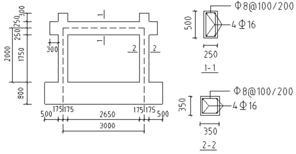
Component design of the infill frame.
Based on the solid finite element model, truss element T3D2 was used to replace the infill with the equivalent diagonal strut. The material properties had the same constitutive masonry relationship using in the infill, and it was stipulated that the truss element T3D2 could only bear the pressure but without tension, corresponding to the physical characteristics of infill walls in actual force. The joint connection in the connector was used between the truss rod and frame column, it meant that there was no relative displacement between the joints, but the relative rotation was allowed. The simplified model is shown in (Fig. 9).
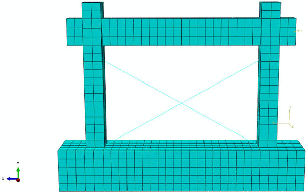
Equivalent diagonal single-strut bracing model.
According to the principle of equal lateral displacement on the top of the column, the value of Δx was adjusted continuously until the load-displacement curves of the equivalent diagonal single-strut bracing model were consistent with the solid finite element model and the value of Δx was recorded at this point. The simulation results with different contact positions between the equivalent bracing walls and the frame columns are shown in Fig. (10).
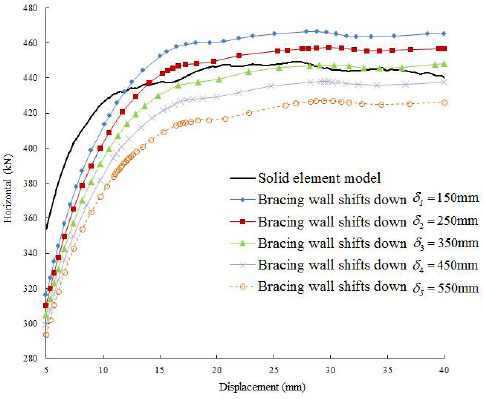
Load-displacement curve of Member 1.
As shown in Fig. (10), the load-displacement curve was most consistent with the results calculated by the solid finite element model when Δx = 350mm, thus the reasonable value of Δx for Member 1 was 350 mm. According to the method above and the analysis of the remaining nine members in the same process, the value of Δx was determined when the load-displacement curves of the equivalent diagonal single-strut bracing model were consistent with the solid finite element model.
3.3. Fitting the Empirical Formula
The steel frame structure was analyzed using a finite element simulation by Liauw [14] in 1984, thereby obtaining the mechanical characteristics of steel frame structures under a horizontal load, where he considered that the effective width of the equivalent bracing wall w is associated with h' cosθ', and the value of w/h' cosθ' can be written as an expression that contains the function λh'. Through the derivation of Eq. (13), w can be expressed via the expression that contains Δx and they have a direct proportional relationship. When combined with the finite element analysis results, it is considered that Δx is associated with h' cosθ' and the value of Δx/h' cosθ' can be written as an expression that contains the function λh', where λ is the relative stiffness parameter first proposed by Stafford Smith [15] in 1969. The formula for calculating λ is:
 |
(28) |
where Em is the elastic modulus of the filled-wall material, Ec is the elastic modulus of concrete, t is the infill thickness, θ is the sloping angle of diagonal of the infill, Ic is the moment of inertia of the column cross-section, and h is the infill height. It shows that λ is the main parameter to calculate the width of equivalent diagonal brace, and it has been widely used. The relative stiffness parameter λ provides a key to the estimation of an infilled frame's behavior and it therefore assumes a prominent role in the development and presentation of the methods for predicting its stiffness and strength. The length of contact, the stiffness of the infill and the strength and sequence of the modes of failure may all be expressed as functions of λ either in algebraic or graphical form.
By calculating the corresponding values of Δx / h' cosθ' and λh' for the 10 design components described above, when Δx took an appropriate value, a series of points were obtained, which were plotted with Δx / h' cosθ' as the ordinate against λh' as the abscissa in the same rectangular coordinate system, as shown in Fig. (11).
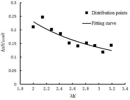
Distribution points and formula fitting curve.
The empirical formula for calculating Δx was obtained from thedistribution points and the formula fitting curve given above as Eq. (29):
 |
(29) |
The relative parameters were identified after determining the scantling and material grade of the wall-filled frame component, where the value of Δx was calculated by Eq. (29). It should be noted that during ABAQUS finite element modeling, for the equivalent diagonal strut concentrated quality and the stiffness of equivalent bracing wall located in the center line of it, the contact position between the rod end and frame column was calculated according to Eq. (16): s = Δx + 0.5αch.
4. Application examples
4.1. Verification of Finite Element Model
As described in Section 2, Y.S. Tong and G.F. Qian who studied the bearing capacity and deformation performance of members in a series of reinforced concrete frame model tests. Simulation verification of C-1 and C-3 was done by solid element model and simplified model described in this paper. Comparing the experimental values with the two finite element modeling method results of the component C-1 and C-3, they are shown in Fig. (12) and Fig. (13).
The calculation results could be seen from the Fig. (12) and Fig. (13). The calculation of maximum horizontal bearing capacity of infill frame though the simplified modeling method described in this article coincided both the experimental data and solid element model results. The rationality and accuracy of the equivalent simplified model were verified.
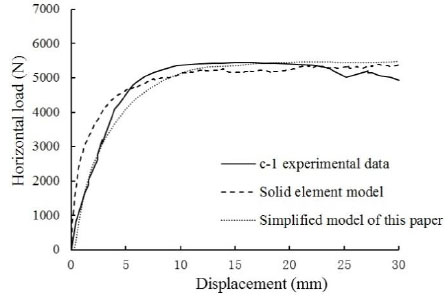
Load-displacement curve of Member c-1.
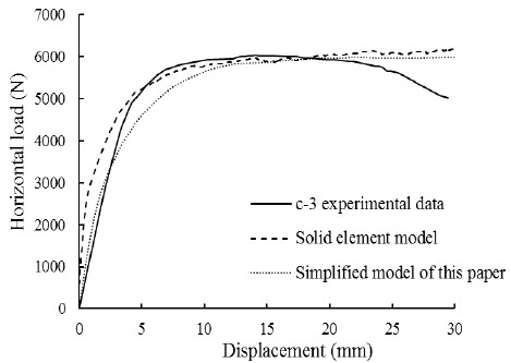
Load-displacement curve of Member c-3.
4.2. Verification of Calculation Formula for Infilled Wall Stiffness
Take one bottom frame structure in Wenchuan earthquake as an example to verify the accuracy of the formula for calculating the stiffness of the infilled wall which was derived in this paper. And explain the influence of the stiffness of the infilled wall on the lateral stiffness ratio of the bottom frame structure though analyzing of calculation results.
Masonry buildings with frame and seismic-wall in the lower stories refers to hybrid bearing buildings which the bottom or the bottom two layers are shear walls, and the upper part is Multistory masonry structure. Because of the more flexible space layout in bottom layer, and it is more cost-effective and shorter construction period than the frame structure, so this kind of building is widely used in street-facing residential or office buildings in China. The structure type is a hybrid structure composed of two different bearing and lateral resistant system, which belongs to a seismic-unfavorable structural system. The relative stiffness between the bottom frame-shear wall story and the transitional masonry layer is controlled by the lateral stiffness ratio. Structural appearance is shown in Fig. (14). The first layer of the structure is infilled frame, there are 33 brick masonry walls in X and Y directions. The first plane graph and infill wall number are shown in Fig. (15).
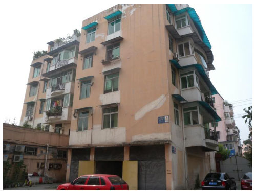
One bottom frame structure in Wenchuan earthquake.

First plane graph and infill wall number.
The calculation formula (17) which was derived in this paper was used for calculating the stiffness of the 33 infill wall. Among them, the infilled walls in X direction were number 1-10 and number 31-33 brick masonry walls. The infilled walls in Y direction were number 11-30 brick masonry walls. In order to verify the accuracy of the Eq. (17), the calculation results were compared with the calculation formula which was from literature [16] for calculating the lateral displacement rigidity of infill wall. The calculation formula which is presented by literature [16] as:
 |
(30) |
 |
(31) |
Where Kw is interlayer lateral stiffness of infill walls, φk is stiffness reduction factor, the upper part of the house uses 1.0, the middle of the house uses 0.6, the lower part of the house uses 0.3, Ew is the elastic modulus of infill wall, Hwis the height of infill wall, Aw and Iw is the cross section area and inertia moment of infill wall, φm and φv is opening influence coefficient. A comparison of the two methods for calculating the stiffness of the infill walls were carried out, and the results are shown in Table 2.
Comparison of computational results of infilled stiffness.
| Direction of structure | Code formula (kN/m) | Ratio of the whole stiffness | New formula (kN/m) | Ratio of the whole stiffness |
|---|---|---|---|---|
| X direction | 203928 | 14% | 242977 | 17% |
| Y direction | 441704 | 17% | 399361 | 15% |
It can be seen from Table 2, both two algorithms show that only some part of the infill wall as a non-structural component is involved in the lateral stiffness. The contribution of the stiffness is less than 20% of their total stiffness, and it is same with the conventional understanding. The calculation results of the two algorithms are close. Considering the whole stiffness of infill wall, the effect of 10% error can be neglected. It also verifies the rationality and accuracy of the derived calculation formula of the infilled stiffness in this paper.
According to the seismic code, the ratio of lateral stiffness of the structure was checked. When the stiffness of infill wall was not included, the lateral stiffness ratio of the structure was shown in (Table 3). And when the stiffness of infill wall was included, the lateral stiffness ratio of the structure was shown in (Table 4).
Lateral stiffness ratio of structure.
| Direction of structure | Lateral stiffness of first floor (×106 kN/m) | Lateral stiffness of second floor (×106 kN/m) | Lateral stiffness ratio |
|---|---|---|---|
| X direction | 3.380 | 5.648 | 1.67 |
| Y direction | 6.600 | 6.917 | 1.05 |
Lateral stiffness ratio of structure including the infilled stiffness.
| Direction of structure | Stiffness of infill wall (×106 kN/m) | Lateral stiffness of first floor (×106 kN/m) | Lateral stiffness of second floor (×106 kN/m) | Lateral stiffness ratio |
|---|---|---|---|---|
| X direction | 0.243 | 3.623 | 5.648 | 1.57 |
| Y direction | 0.399 | 6.999 | 6.917 | 0.99 |
In our country, the lateral stiffness ratio of the bottom frame structure should be controlled between 1.0 and 2.5. It can be seen from Table 4 that the lateral stiffness ratio of the structure in Y direction is less than 1.0 when the stiffness contribution of the infill wall in first layer is included. The lateral stiffness ratio is less than 1.0, which means that the seismic capacity of the bottom layer of the structure is too strong, so that the weak floor is transferred from the bottom floor to the masonry floor in the upper part of the structure. It is also in line with the actual damage that the first layer is slightly damaged, and the second layer is damaged seriously. Therefore, it will produce erroneous results when the stiffness contribution of the infill wall is ignored completely during the design of the building structure. So it is suggested that the effect of the infill wall on the stiffness should be considered.
4.3. Verification of Calculation Formula for Infilled Wall Shear Resistance
The calculation formula (8) which was derived in this paper was used for calculating the shear resistance of the 33 infill wall. The first plane graph and infill wall number were same with (Fig. 15). The calculation results were compared with the calculation formula which was from literature [16] for calculating the shear resistance of infill wall. The calculation formula which was presented by literature [16] as:
 |
(32) |
 |
(33) |
Where Vmy is shear resistance of infill wall, fvE is design value of seismic shear strength of masonry along the stepped cross section, fv is non-seismic design value of shear strength of masonry, ζN is normal stress influence coefficient of shear strength of brick masonry, Am is the cross section area of infill wall. A comparison of the two methods for calculating the shear resistance of the infill wall was carried out, and the results were shown in Table 5.
Comparison of computational results of infilled wall shear resistance.
| Direction of structure | Code formula (kN) | New formula (kN) | Difference |
|---|---|---|---|
| X direction | 1380.2 | 1024.1 | 25.8% |
| Y direction | 2353.5 | 1458.0 | 38% |
From the results of calculation, the calculation of the code formula of infill wall shear resistance is high, and the reduction factor 0.7 in code formula is not clear. The value is based on engineering experience in a large extent, and it is lacked in strict theoretical derivation. In contrast, the formula which is derived in this paper is more rigorous, the form is more simple and intuitive, the concept is clearer and the results are more consistent with the actual situation. Compared with the bare frame, 1024kN is increased in X direction and 1458kN is increased in Y direction. This part of increasing shear resistance is provided by the infill wall. It can be seen that the shear bearing capacity of the infill wall should not be ignored completely. And the shear resistance of the infill wall should be included in the calculation of the ultimate bearing capacity of frame-shear wall stories.
Conclusion
- In the earthquake engineering area, simulations of wall-filled frame structures often use a macroscopic equivalent model based on certain hypotheses, where the infill wall is simplified as an equivalent diagonal strut. In this study, this method was improved by combining the situation where the brick masonry between the top of the infill wall and the corner of beam–column joint is crushed during a strong earthquake, thereby decreasing the contact position between the equivalent bracing walls and the frame columns to a certain distance and putting forward a new calculation model. This paper provided a force analysis based on this model, as well as formulae for calculating the contact length between the equivalent bracing walls and the frame columns, the shear bearing capacity of the wall-filled frame, and the actual participation of the infill wall in the stiffness.
- Using the ABAQUS finite element simulation method and based on comparisons with the data obtained by testing, it was demonstrated that the results calculated by the solid finite element method were consistent with the actual empirical data. Based on these assumptions and the results calculated for the related parameters, the infill was replaced with an equivalent diagonal strut and built an equivalent diagonal single-strut bracing model. According to the principle of equal lateral displacement on the top of the column, the reasonable contact position between the equivalent bracing walls and the frame columns was determined, and fitted the empirical formula, Eq. (21), using the numerical simulation results. A new simplified finite element modeling method was proposed for a wall-filled frame combined with Eq. (13). Through comparing the finite element model calculation results with the experimental data, the validity of the simplified modeling method was verified.
- As a non-structural member, the shear resistance and stiffness of infill wall is often neglected in previous design, which only gravity load can be included. However, research shows that the neglect of the infill wall elements in the design phase is not always safe. For example, in this project, when the stiffness of the infill wall is neglected, the lateral stiffness ratio meets the requirement. When the infill wall stiffness is included, the lateral stiffness ratio of the structure is less than 1.0, which does not meet the seismic code requirements. At present, there is no clear conclusion about the calculation method of the stiffness and shear resistance of the infill wall. The formulas which are derived in this paper are verified out by the actual seismic calculation of one bottom frame structure. That can provide reference for the designer in the calculation of the stiffness and shear resistance of the infill wall.
CONFLICT OF INTEREST
The authors confirm that this article content has no conflict of interest.
ACKNOWLEDGEMENTS
This research is supported by the special research in Chinese seismological industry (201508026), major research plan of national natural science foundation of china (91315301-10) and special research in Chinese seismological industry (201508010).


