All published articles of this journal are available on ScienceDirect.

Study on Cross-shaped Concrete Filled Steel Tubular Stub Columns Subjected to Axial Compression: Experiments and Design Method
Authors Info & Affiliations
Abstract
Despite its wide application prospect, researches on the cross-shaped concrete filled steel tubular (CFT) columns are scarce, and no design method can be used. This paper concerns with the axial load behavior of cross-shaped CFT stub columns. Five specimens were tested to examine the influences of three parameters on the characteristics of failure, the bearing capacity and deformability. The parameters include the width-thickness ratios of steel plates, the yield strengths of steel and the sectional dimensions. Experimental results demonstrate that the global outward bulge of steel tube near the concave corners is significant, so that the stresses on the steel tube distribute unevenly and the confinement effects on the concrete are inferior to the rectangular CFT columns. By decreasing the width-thickness ratio of each steel plate, the global outward bulge near the concave corners was smaller, but the ductility could be improved only when it decreased by 2.08 times. By increasing the yield strength of steel to 1.47 times, the bearing capacity and deformation were inversely smaller, but the ductility was increased. By increasing the length-width ratio of each leg to 2.25 times, the global outward bulge was increased and local buckling occurred earlier. Then the application scopes for evaluating the maximum strength of specimens by the methods in design codes are provided. A new method is also proposed by considering the confinement effects of concrete and the strength loss of steel tube. The results predicted by the proposed method show good agreement with the experimental ones.
1. INTRODUCTION
Concrete-filled steel tubular (CFT) columns have been widely used as structural members. Extensive investigations have been carried out to study the mechanical performance of circular, square and rectangular CFT columns [1-5], and several researches focused on the special-shaped CFT columns, such as the T-shaped, L-shaped and elliptic CFT columns [6-11], while the studies on other kinds of special-shaped CFT columns were scarce, such as the cross-shaped CFT columns [12-16]. The study results show that the mechanical behavior of special-shaped CFT columns with flat steel plates or concave corners, such as the L-shaped, T-shaped and cross-shaped CFT columns, is inferior to that of circular CFT columns. It is because that the flexural stiffness around the middle area of each steel plate of a special-shaped CFT column is weaker to resist the outward extrusion of core concrete, like the case of square and rectangular CFT columns. Especially, the length of several steel plates of the T-shaped and L-shaped CFT columns is larger than the others, so failure always occurs around these areas. What is worse, for the special-shaped CFT columns with concave corners, the steel tube near these concave corners bulges entirely outward, because the transverse resultant force of the two steel plates next to the concave corners is directed outward under the outward extrusion of concrete. It results in a further loss of bearing capacity and deformability. On the aggregate, if the width-thickness ratios of steel plates are the same, the total confinement effects on core concrete of the special-shaped CFT columns are remarkably smaller than those of the circular CFT columns, and the stresses of special-shaped steel tube distribute unevenly, especially for the CFT columns with concave corners.
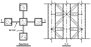
However, special-shaped CFT columns, mainly the L-shaped, T-shaped and cross-shaped CFT columns, have been extensively used in engineering structures in recent years [17], on account of their convenient construction at beam–column joints, larger moment of inertia of cross-section, and improved agreement with the design need of the architectural schemes. Especially, there are two symmetrical axes in a general cross-shaped section, so compared with the L-shaped and T-shaped CFT columns, the mechanical behaviors of the cross-shaped CFT columns in different loading directions under cyclic load are more uniform. Only a few of researches on the mechanical performances of cross-shaped CFT columns have been conducted. Based on the nonlinear analysis method, Cao [12] studied the influences, load angle, axial compression ratio, steel ratio and yield strength of steel tube, on the curvature ductility coefficient of cross-shaped CFT columns under biaxial bending and compression. A type of cross-shaped CFT column composed of square CFT columns is proposed by Chen [13], as shown in Fig. (1), and the calculation method and mechanical property of slender specimens were studied by the superposition theory, finite element analysis and axial compression experiment.
Despite its wide application prospect, researches on the cross-shaped CFT columns are scarce, and no design code provides design guidelines of these members that can be used in engineering projects. In this paper, experimental investigations conducted on five normal cross-shaped CFT columns subjected to axial compression, are reported. The primary parameters considered in this test program are: (1) maximum width-thickness ratios of steel plates (
 ); (2) yield strengths of steel (fys); (3) sectional dimensions (k=α1/b1 or b2/a2). These factors were experimentally investigated to assess their influences on the characteristics of failure, the bearing capacity and deformability, and the stress distribution on the steel tube. Then, through comparing the results predicted by the methods in the design codes (ACI [19], EC4 [20], GJB [21] and DBJ [22]) with the experimental results, the scopes of application about the parameters for each method, such as the limits of the maximum width-thickness ratio of steel plates and the relevant steel strength, are suggested. These methods are optional methods to predict the strength of cross-shaped CFT stub column, but the application scopes are small. Finally, to establish a method with wider applicability, by considering the confinement effects of concrete and strength loss of steel tube, a theoretical method is proposed and verified by the test results.
2. EXPERIMENTAL PROGRAM
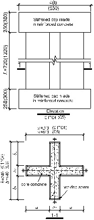
Five 1:3 scale cross-shaped CFT stub columns designated as the specimens C1~C5 were tested. The details of the specimens are shown in Table 1 and Fig. (2). The maximum width-thickness ratios (
) range from 11 to 39. The yield strengths (fys) range from 239MPa to 348MPa. The values of α1/b1 and b2/a2 are both equal to 1 for the specimens C1-C4, while they are equal to 2.25 for the specimen C5. Namely, the sections of all specimens are symmetrical around two axes. The initial clear height is 720mm for the specimens C1-C4, while it is 1320mm for the specimen C5. The steel tubes were fabricated by welding twelve steel plates together. Based on the study results of Uy [23], if the width-thickness ratio of heavily welded steel plate is smaller than the yield width-thickness ratio limit which is about 65, the ultimate strength is not affected by the residual stresses. Besides, the test results in this paper showed that the local buckling occurred after the peak load for all the specimens. Therefore, in this study, it is assumed that the ultimate strength is not significantly affected by the residual stresses due to welding. The characteristic 28-day cubic compressive strength of concrete (fcu,k) for all the specimens is 54.7MPa.
| No. | a1/ a2/ b1/ b2/ t | fck/ fys |
|
εb /εu /ε85/×10-6 | DI | Nb | Nu |

|

|
|---|---|---|---|---|---|---|---|---|---|
| (mm) | (MPa) | (kN) | (kN) | ||||||
| C1 | 80/ 80/ 80/ 80/ 3.64 | 41.58/ 348 | 27 | (9579)/ 3486/ 5472 | 1.57 | (1520) | 2064 | 0.89 | (0.66) |
| C2 | 80/ 80/ 80/ 80/ 5.6 | 41.58/ 346 | 17 | —/ 5532/ 7936 | 1.43 | — | 2754 | 0.96 | — |
| C3 | 80/ 80/ 80/ 80/ 7.74 | 41.58/ 261 | 11 | —/ 5747/ 33830 | 5.89 | — | 3326 | 1.17 | — |
| C4 | 80/ 80/ 80/ 80/ 3.72 | 41.58/ 239 | 22 | (11883)/ 3692/ 4772 | 1.29 | (1410) | 2155 | 1.10 | (0.72) |
| C5 | 180/ 80/ 180/ 80/ 5.6 | 41.58/ 346 | 39 | (5647)/ 2842/ 6406 | 2.25 | (3633) | 4096 | 0.75 | (0.67) |
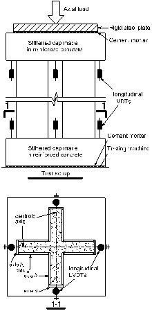
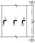
A 15000kN universal testing machine was employed to carry out the test, and the loading position was the centroid point of cross-shaped section, as shown in Fig. (3). Four pairs of linear variable displacement transducers (LVDTs) were arranged longitudinally between the two caps to measure the axial shortening of four symmetrical positions along the centroid axes, respectively. The average longitudinal strain (ε) can be calculated by dividing the average displacement difference, obtained from four pairs of LVDTs, by the initial clear height of specimen (L). The wire strain gauges were arranged on the steel tube near the mid-height to measure the transverse and longitudinal strains of the steel plates.
The specimens were loaded by monotonically increasing vertical displacement at a rate of 0.2mm/min. The global outward bulge and local buckling of steel tube were observed during the test. The loads when local buckling orrured were recorded. Testing was terminated when the longitudinal deformation became excessively large and the outward bulge of steel tube was obvious.
3. EXPERIMENTAL RESULTS AND DISCUSSIONS
The experimental results are shown and discussed in this section, such as the experimental phenomena and failure modes, characteristics of load bearing and deformability, and the strain of steel plate.
3.1. Experimental Phenomena and Failure Modes
The typical failure modes of specimens were local buckling of steel plates and global outward bulge of steel tube at the concave corners near the mid-height of the column, as shown in Fig. (4). The maximum width-thickness ratios of steel plates of the specimens C1, C4 and C5 (
=27, 22 and 39, respectively) are relatively large among the specimens. The failure modes of them were similar. When reaching the maximum load, global outward bulge of steel tube at the concave corners were found. At the load descending stage, local buckling appeared randomly on the steel plates with relative larger width-thickness ratio, such as the side-α1 steel plate and the side-b1 steel plate. Global outward bulge of steel tube at the concave corners were more obvious at the late loading stage, and each leg of the cross-shaped steel tube deformed similarly as a single column which was subjected to eccentric compression. The failure modes of specimens C2 and C3, whose
are relatively small among the specimens, were similar with those of the specimens C1, C4 and C5, but the globe outwart bulge at the concave corners was smaller, and no local buckling of steel plate was found till the end.
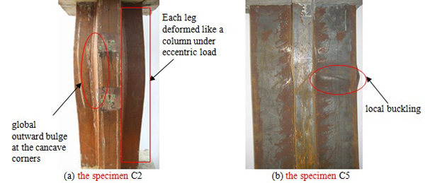
The experimental phenomena indicate that the width-thickness ratio of steel plate is a key factor affecting the failure modes of a cross-shaped CFT stub column. On the other hand, as distinguished from the CFT columns without concave corners, the global outward bulge of the steel tube at the concave corners of the cross-shaped CFT columns has significant influences on the mechanical behavior. Besides, increasing the yield strength of steel has little effect on the failure modes.
3.2. Characteristics of Load Bearing and Deformability
The curves of load (N) versus average longitudinal strain (ε) of all specimens are shown in Fig. (5). The loads corresponding to the initiation of local buckling (Nb) are marked on the curves, designated as B1 to B5, where the points B2 and B3 are absent because local buckling was not found for the specimens C2 and C3. Table 1 lists the key results on the curves, including the experimental maximum loads and corresponding average longitudinal strains (Nu and εu), the loads and corresponding average longitudinal strains at the points B (Nb and εb), the ratios Nu/Nun and Nb/Nun, and the ductility indexs DI=0.75×(ε85/ε75) [18]. As shown in Fig. (5) and Table 1, the characteristics of load bearing and deformability of the specimens are as follows.
-
The maximum loads (Nu) of the specimens C3 and C4 are larger than their nominal strengths (Nun), Nu/Nun≥1, respectively. The so-called nominal strength, Nun=fckAc+fysAs, is the theoretical maximum strength of a CFT column in a case that the average stresses of the concrete and the steel tube are fck and fys, respectively. When the parameters velevant to the longitudinal strength of specimens, such as the thickness and strength of steel tube, are changed, it is more meaningful to investigate the load bearing characteristics by the ratio N/Nun than by the practical load (N) directly. Essentially, when other parameters are the same, there are three factors affecting the ratio of a practical load (N) and the nominal strength (Nun), such as the Nu/Nun and the N85/Nun, where N85 refers to the load when it falls to 85% of the maximum load. Besides, they also affect the value of deformation in these conditions, such as the εu and ε85. Take the ratio Nu/Nun for example, firstly, by increasing the confinement effects of the steel tube on the core concrete, the mean strength and the elastoplastic deformation capacity of core concrete are larger than the plain concrete, then the ratio N/Nun is increased, and the average longitudinal strain (εu) is increased too. Second, if the stresses of steel tube distribute more uniformly due to a smaller extent of outward bulge, more area of steel tube can reach yield at the peak load, then the ratio Nu/Nun is increased. It also contributes to a larger deformation (εu), because the plastic deformation capacity of the integral steel tube section is increased. Third, when the total strength of steel tube which contributes to the bearing capacity of the column is smaller, the ratio Nu/Nun and the relevant deformation (εu) are increased. It is because that the strength loss of steel tube caused by a same extent of outward bulge or local buckling is smaller. However, if the extent of outward bulge is effectively reduced and meanwhile the total strength of steel tube is increased, for instance, by increasing the thickness of steel tube, the ratio Nu/Nun is also enhanced. For other loading stage, these three factors also influence the ratio N/Nun and the relevant deformation (ε), only the extent of impact of each factor changes.
For the specimen C3, the width-thickness ratio of the side-α1 steel plate is the smallest of all specimens, and from the experiment, the outward bulge of steel tube is also the smallest. It gives rise to the largest confinement effects on the core concrete, and the longitudinal stresses of almost the whole steel tube can reach yield at the peak load, as discussed later. As a result, the ratio Nu/Nun reaches 1.17. For the specimen C4, the yield strength of steel is only 239MPa and its thickness of steel tube is relatively small (t=3.72mm), so the total strength of steel tube which contributes to the bearing capacity of the column is the smallest of all specimens. Besides, part of the core concrete near the convex corners is constrained. Both the cases above are beneficial to the increase of ratio Nu/Nun, and the beneficial effects are larger than the adverse effects due to a relatively small t. As a result, for the specimen C4, the ratio Nu/Nun reaches 1.1. For the specimens C1, C2 and C5, the steel tubes have larger contribution to the cross section bearing capacity than the case of specimen C4, and the outward bulge of steel tubes is larger than the case of specimen C3 because the width-thickness ratios of steel tubes are larger. As a result, the ratios Nu/Nun are all smaller than 1.0. Especially, for the specimen C5, the width-thickness ratio of the side-α1 steel plate is the largest. The ratio Nu/Nun of it is only 0.75 on account of large outward bulge of steel tube.
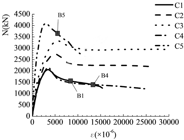 Fig. (5). Load (N) - average longitudinal strain (ε) curves.
 - The parameters of specimens C1 and C2 are nearly the same except for the thickness of steel tube, tC2/tC1=1.54. The situation is similar between the specimens C3 and C4, tC3/tC4=2.08. As shown in Fig. (5), with the increase of t, namely, the decrease of width-thickness ratio of each steel plate, the initial axial rigidity is larger, and the strength-descending rate after the peak load is generally smaller. There is an increase of the ratio Nu/Nun by 8% and an increase of the relevant εu by 59%, compared the specimen C2 with the specimen C1, as shown in Table 1. And, they are 6% and 56%, respectively, compared the specimen C3 with the specimen C4. In fact, by increasing t, the flexural stiffness for resisting outward bulge of steel tube is increased, so that the outward bulge of steel tube, especially the areas near the mid-width of each steel plate and the areas near the concave corners, is smaller. As a result, the confinement effects of steel tube on the core concrete are improved. Besides, the stresses on the steel tube distribute more uniformly, so that the relevant total axial strength of the steel tube is increased. These two effects lead to the increases of ratio Nu/Nun and the relevant εu.Furthermore, although the difference of thickness between the specimens C3 and C4 (tC3/tC4) is larger than that of the specimens C2 and C1 (tC2/tC1), the increasing rates of Nu/Nun and εu between the specimens C3 and C4 are merely approximative to those between the specimens C2 and C1. The reason is, as discussed before, the total strength of steel tube of the specimen C4 which contributes to the bearing capacity of the column is the smallest of all specimens, so that the ratio Nu/Nun and εu of the specimen C4 are both relatively large and more closer to those of the specimen C3. In addition, the ε85 of the specimen C2 is 1.45 times that of the specimen C1, and it is 7.09 times compared the specimen C3 with the specimen C4. It indicates that the load resistant capacity at the post-peak stage is increased by increasing t. Furthermore, as distinguished from the εu, the increasing rates of ε85 are considerably different for the specimens with varied yield strength of steel and varied increasing rate of t. As it can be seen, the increasing rate of ε85 is smaller than that of εu, compared the specimen C2 with the specimen C1, tC2/tC1=1.54. But, it is significantly larger than that of εu, compared the specimen C3 with the specimen C4, tC3/tC4=2.08. It is because the trend of outward extrusion of core concrete and the trend of outward bulge of steel tube in the post-peak stage are extremely larger than those in the pre-peak stage. In the post-peak stage, it has a larger demand on the flexural stiffness of steel tube for resisting outward bulge and preventing large strength loss. Besides, with larger yield strength of steel, the strength loss of the specimen C2 caused by outward bulge of steel tube in the post-peak stage is larger, so that the increasing rate of ε85 compared with the specimens C2 and C1 should be smaller. Similarly, although the indexes εu and ε85 that reflected the deformability are both increased by increasing t, another index, the ductility index DI, does not change in the same way. The DI, which is essentially the ratio of ε85 and ε75, is increased by 4.57 times compared the specimen C3 with the specimen C4, but it is 0.91 times compared the specimen C2 with the specimen C1. It means that the ductility can only be increased in case that the increasing rate of t is large enough. It is because that the increasing rates of ε75 and εu by increasing t are approximative according to the experimental data, but the increasing rate of ε85 only becomes larger than that of εu by increasing a large amount of t, such as the case between the specimens C3 and C4.
- The difference between the specimens C2 and C5 is the sectional dimension (k=α1/b2=b1/a2). As shown in Table 1, for the specimen C5 (k=2.25), the ratio Nu/Nun that is related to the confinement effects of concrete and axial strength of steel tube, and the values of εu, ε85 and DI that are related to the deformability, are all smaller than those of the specimen C2 (k=1). It is because that the width-thickness ratios of the steel plates on the side-α1 and side-b1 increase by increasing k. Besides, the strain that local buckling of the specimen C5 appeared (εb) is the smallest of all specimens.
- The parameters between the specimens C1 and C4 are similar except that the yield strength of steel (fys) of the specimen C1 is 1.46 times that of the specimen C4. As shown in Fig. (5), no influence on the initial axial rigidity of specimen can be found by varing the fys. As shown in Table 1, the values of Nu, Nu/Nun, εu, ε85, and DI of the specimen C1 are 0.96, 0.81, 0.94, 1.15 and 1.22 times those of the specimen C4, respectively. By increasing fys, the transverse stresses of steel tube become larger at the peak load. It is beneficial to increase the confinement effects on core concrete. As a result, logically, it seems that the values of Nu, Nu/Nun, εu, ε85, and DI should all become larger. However, other situations should be considered. First, increasing fys has no influence on the flexural stiffness of steel plate. It means that, for the specimens C1 and C4, the extent of outward bulge of steel tube and the relevant stress distribution pattern should be similar. Second, by increasing fys, the strength loss of steel tube caused by a same extent of outward bulge should be larger, because the axial strength of steel tube that contributes to the cross section bearing capacity becomes larger. Synthesize the adverse effect on the strength loss of steel tube and the beneficial effect on constraining the concrete, by increasing fys in a certain amount, such as that in this experiment, the values of Nu, Nu/Nun and εu may inversely become smaller. In addition, the outward extrusive defomation of concrete in the post-peak stage is larger. So, in the post-peak stage, the steel tube with a larger fys can provide larger transverse stresses to constrain the concrete than those in the pre-peak stage. Then, by increasing fys, the indexes ε85 and DI related to the load resistant capacity in the post-peak stage may become larger.
3.3. Strain of Steel Plate
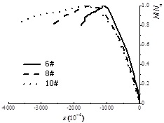
The width-thickness ratio of the side-α1 steel plate in the specimen C5 is the largest of all the specimens. As a typical example, the strain distribution characteristic on the side-α1 steel plate in the middle height of the specimen C5 are investigated. The positions of wire strain gauges are shown in Fig. (6). The curves of normalized loads (N/Nu) versus longitudinal strains (εL) and transverse strains (εH) on the side-α1 steel plate of the specimen C5 are shown in Fig. (7) and Fig. (8).
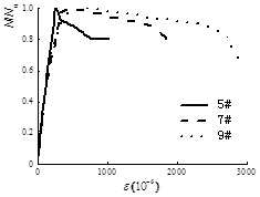
The average longitudinal strains (ε) of all specimens, achieved from the readings on LVTDs, have reached yield at the peak load, as shown in Fig. (5). However, not all the longitudinal strains on the steel plate, achieved from the readings on strain gauges, can reach yield, as shown in Fig. (7). Besides, the compressive strains increase from the convex corner to the concave corner given by 6#<8#<10#. It is because that the areas near the concave corners tend to bulge outward integrally under the outward extrusion of core concrete. It makes each leg of the cross-shaped steel tube deform similarly as a single column subjected to eccentric compression, and the global outward bulge near the convex corner of each leg is the largest, as shown in Fig. (4). As a result, the longitudinal strains of steel tube cannot distribute uniformly. Furthermore, from the test results of other specimens, the longitudinal strains distribute more unevenly along with the increase of global outward bulge, and more area of steel plate cannot reach yield.
As shown in Fig. (8), when reaching the maximum load, all the transverse strains have not reached yield. It reflects that the confinement effects on the core concrete at the peak load are small. However, it can be seen, in the post-peak stage, the transverse strains develop faster due to larger extrusion deformation of concrete. On the other hand, the global outward bulge of steel tube near the concave corner is so obvious that εH of 7# and 9# develop faster than that of 5#, especially in the post-peak stage.
4. DESIGN METHODS
The methods for evaluating the maximum strength of axially loaded square or rectangular CFT columns are included in the existing design codes, such as the ACI [19], EC4 [20], GJB [21] and DBJ [22]. However, there is not any special method in design codes that can be used to evaluate the maximum strength of the cross-shaped CFT stub columns. The design methods in the existing codes can be optional methods to predict the strength of cross-shaped CFT stub column, but the application scopes should be smaller than the requested scopes in the codes. Therefore, at first, the application scopes of the maximum width-thickness ratio of steel plates and the strength of steel are discussed. Then, to establish a method with wider applicability, a theoretical method that adopts the superposition theory is proposed according to the experimental results in this paper. This proposed method practically considers the confinement effects of the cross-shaped steel tube on core concrete, together with the loss of longitudinal strength of steel tube caused by the outward bulge.
4.1. Application Scopes of the Design Methods in the Codes
Table 2 gives the comparison between the maximum strengths obtained by the methods in the codes and the experimental maximum loads (Nuc/Nu). As shown in Table 2, the experimental results of the specimens C1, C2 and C5 are obviously overestimated by the methods in the codes GJB and DBJ to at least 10%, while the evaluated strengths of the specimens C3 and C4 are relatively closer to the experimental results, especially for the specimen C3. The methods in the codes GJB and DBJ take into account the confinement effects of square or rectangle steel tube on the core concrete by applying magnification factors to the axial strength of the whole composite section. They require smaller limits of the width-thickness ratio of steel plate than those in other codes. For example, the
should be smaller than 40 according to the code GJB, while it is equal to 52 in the code EC4. The purpose of stipulating smaller width-thickness ratio limit is to prevent large outward bulge or local buckling on the mid-span region of each steel plate in the square or rectangular CFT columns, so that more area of the steel tube can reach yield and the confinement effects on the core concrete are larger. Furthermore, the magnification factors considered in the code DBJ are larger than those in the code GJB.
Theoretically, for the cross-shaped CFT columns, if the confinement effects on the concrete and the stress distribution condition of steel tube are similar to those of square or rectangular CFT columns, the maximum strength can be evaluated by the codes GJB and DBJ. However, although the maximum width-thickness ratios of steel plates of all specimens (
= 11~39) do not exceed the limits that stipulated in the codes GJB and DBJ, but only the experimental results of the specimen C3 and C4, with the width-thickness ratios only 27% and 54% of the limit, respectively, are approximate to the predicted results. In fact, at the peak load, the global outward bulge of cross-shaped steel tube near the concave corners has key and significant effects on the stress distribution pattern of the steel tube and the confinement effects on the concrete, because in the test, the outward bulge or local buckling that occurred near the mid-span region of each steel plate was not obvious in the pre-peak stage. Under the transverse tensile stresses of the side-α1 and side-b1 steel plates, the concave corner of steel tube is subjected to an outward resultant force. So the edge intersected by the side-α1 and side-b1 steel plates can rotate and deform outward, and cannot be seen as a strict restrained boundary of the steel plates. The boundary conditions of the side-α1 or side-b1 steel plate are more like being restrained elastically at the edge near the convex corner and being freedom at the edge near the concave corner. It is different from the boundary conditions of steel plates in a square or rectangular CFT column, which are restrained elastically at the both edges [24]. As a result, to restrict the global outward bulge at the concave corners and the local buckling in the mid-span of steel plates, the width-thickness ratio limit of the cross-shaped CFT columns should be smaller than that of the square or rectangular CFT columns, such as the case of the specimen C3.
Additionally, the adverse effects of outward bulge augment when the contribution of axial strength of steel tube to the bearing capacity is larger. For example, although the
of the specimen C2 is smaller than that of the specimen C4, but its yield strength of steel is larger. Then the predicted results from the codes GJB and DBJ are unsafe for the specimen C2. Actually, for the specimen C4, although the differences between the Nuc and the Nu are less than 10%, but the maximum load in the experiment is somewhat overestimated, such as that the values of Nuc/Nu from the codes GJB and DBJ are 1.905 and 1.101, respectively. It is because that the thickness of steel plate of the specimen C4 is somewhat small. On the whole, for the cross-shaped CFT columns, conservatively, the methods in codes GJB and DBJ are suitable to evaluate the maximum strength of the columns with obvious confinement effects and with small loss of strength of steel tube caused by outward bulge, namely, with small width-thickness ratio of steel plate and small yield strength of steel, fys≤261MPa and
≤11, like the specimen C3.
The methods in the codes ACI and EC4 adopt the superposion method by simply combining the total yield strength of steel tube with the total axial strength of plain concrete. In fact, the theoretical value predited by the method in code EC4 is nearly the same as the nominal strength (Nun), except that the cylindar axial compressive strength of concrete (fc') is adopted in the fomula of code EC4, fc'=0.79fcu,k. For the code ACI, an additional reduction coefficient 0.85 is adopted to decrease the strength of core concrete, so the calculated values are the smallest of the four codes. However, the strength reduction coefficient about core concrete cannot actually reflect the mechanical behaviour of cross-shaped CFT column. As shown in Table 2, both the standard deviation values of the Nuc/Nu, achieved from the codes ACI and EC4, are large. The method in code EC4 is suitable to evaluate the maximum strength of the columns without obvious confinement effects and with small loss of strength of steel tube, namely, with relative larger width-thickness ratio of steel plate than that of the specimen C3 and with small yield strength of steel, fys≤239MPa and
≤22, like the specimen C4. The method in code ACI, numerically, is suitable to evaluate the maximum strength of the columns without confinement effects and with large loss of strength of steel tube, namely, with relative large width-thickness ratio of steel plate and with large yield strength of steel, fys≤348MPa and
≤27, like the specimens C1 and C2. For the specimen C5, the yield strength of steel is large, fys=346MPa, and the width-thickness ratio of side-α1 steel plate is the largest,
=39, but it is still smaller than the limits required in the codes. However, the values of Nuc/Nu are 1.3~1.6, namely, its strength is significantly overestimated by all the methods in design codes.
4.2. Proposed Method
By considering the confinement effects of the cross-shaped steel tube on the concrete, together with the loss of longitudinal strength of steel tube caused by outward bulge, a method for predicting the maximum strength of cross-shaped CFT columns with symmetrical section is proposed.
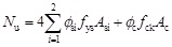 |
(1) |
where Asi and Ac are the area of each steel plate and the area of core concrete, respectively; ϕsi is the strength reduction coefficient of each steel plate; i is the label of each steel plate, i=1 denotes the typical steel plates in a symmetrical cross-shaped section which are composed of the side-α1 and side-b1 steel plates, and i=2 denotes the other typical steel plates, such as the side-α2 steel plate; ϕc is the strength magnification coefficient of core concrete used to consider the confinement effects.
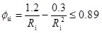
The method raised by Ge [4] to calculate the value of ϕsi of the square or rectangular CFT columns is used for reference. It is suitable for the side-a2 steel plate directly. For the side-α1 and side-b1 steel plates, as discussed above, their boundary conditions are more like being restrained elastically at the edge near the convex corner and being freedom at the edge near the concave corner. So, it can be simply assumed that these two steel plates deform together as one steel plate, even there is an angle between them. According to Ge [4], when Ri≤0.85, local buckling will not occur before reaching the maximum load, then, where Ri is the coefficient about width-thickness ratio of each steel plate, calculated by
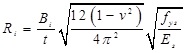 |
(2) |
where v is the Poisson’s ratio of steel; Bi is the width of each steel plate, especially, the side-α1 and side-b1 steel plates are assumed as one steel plate. When Ri>0.85, the loss of longitudinal strength of steel tube due to outward bulge or local buckling should be considered. ϕsi can be calculated by
 |
(3) |
ϕc is obtained by regression analysis method from the experimental data in this paper, and it is expressed by
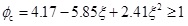 |
(4) |
where
 , it is called the confinement coefficient adopted in the code GJB.
As shown in Table 3, most of the experimental results are well predicted by the proposed method, except that of the specimen C5. The Nuc/Nu of the specimen C5 is equal to 1.153. It is somewhat overestimated, but it is already far more close to the experimential results than those predited by the design codes. Conservatively, the proposed method can be adopted to accurately predict the maximum strength of the columns with
≤30 and fys≤345MPa.
| No. | C1 | C2 | C3 | C4 | C5 | Mean value | Standard deviation |
|---|---|---|---|---|---|---|---|
| Results | 1.100 | 1.018 | 0.981 | 1.028 | 1.153 | 1.056 | 0.069 |
CONCLUSION
The following conclusions can be drawn based on the results of this study.
- The global outward bulge of steel tube near the concave corners of the cross-shaped CFT columns is significant at the peak load. It makes the stresses on the steel tube distribute unevenly, and the confinement effects on the concrete are inferior to the rectanglar CFT columns. So the width-thickness ratio limit of steel plate should be smaller than that of the square or rectangular CFT columns.
- With the decrease of width-thickness ratio of each steel plate, the global outward bulge near the concave corners was smaller, the confinement effects on the core concrete were increased, but the ductility could be improved only when it decreased by 2.08 times.
- By increasing the yield strength of steel to 1.47 times, the bearing capacity and deformation at the peak load were inversely smaller, but the ductility was increased.
- By increasing the length-width ratio of each leg of the cross-shaped section to 2.25 times, the global outward bulge was increased and local buckling occurred earlier, the deformability became smaller.
-
Based on the experimental results in this paper, conservatively, the methods in codes GJB and DBJ can be adopted to evaluate the maximum strength of the cross-shaped CFT columns with fys≤261MPa and
≤11. The method in code EC4 can be adopted to evaluate the maximum strength of the columns with fys≤239MPa and
≤22. The method in code ACI can be adopted to evaluate the maximum strength of the columns with fys≤346MPa and
≤27.
-
The results predicted by the proposed method show better agreement with the experimental results than those provided by the design codes. Accurately, it can be adopted to predict the maximum strength of the columns with
 ≤30 and fys≤345 MPa.
CONFLICT OF INTEREST
The authors confirm that this article content has no conflict of interest.
ACKNOWLEDGEMENTS
This work was financially supported by the National Natural Sciences Foundation of China (No. 51408230, No. 51578246), the Fundamental Research Funds for the Central Universities (No. 2014ZM0015), the State Key Lab of Subtropical Building Science, South China University of Technology (No. 2013ZC14, No. 2013ZC20), Guangzhou Pearl River New Star of Science & Technology Project (No. 201610010077), and the Guangdong Provincial Natural Science Foundation of China (No. S2013040015140).

