All published articles of this journal are available on ScienceDirect.

Criteria for Preliminary Design of an Arched Steel Bridge on Shallow Foundation Under Soil Liquefaction Conditions
Authors Info & Affiliations
Abstract
Introduction:
The research is based on a proposed new foundation design method of bridges on liquefiable soil, consisting of using a shallow foundation and exploiting the liquefiable soil layer as natural seismic isolation, replacing thus the commonly employed deep foundation method. The use of this concept may be hindered by detrimental effects, such as large displacements and rotations that are expected to take place at the foundation of the structure during a strong seismic event, associated with permanent displacements due to the liquefaction phenomenon.
Methods:
The aim of the current study is to investigate the response of an arched steel bridge with two simply supported spans to displacements and rotations induced by soil liquefaction, delineate the acceptable limits of such ground movements that the bridge can sustain, avoiding the collapse of the superstructure, and define criteria for the preliminary design of the spread footing of the middle pier. To that effect, nonlinear analyses are performed, taking into account geometric and material nonlinearities. Displacements and rotations are imposed at the base of the pier and their amplitude is gradually increased until the first group of structural elements that reach failure is detected.
Results and Conclusion:
The values of displacements and rotations, for which failure occurs, specify the tolerable design limits. This is a first step towards investigating the feasibility of the above concept for bridges of this type.
1. INTRODUCTION
According to current international practice, the use of shallow foundation for heavy structures such as bridges, founded in soil susceptible to liquefaction, is avoided. The conventional pile foundation method is employed, ensuring that the imposed loads are transmitted to deeper, non-liquefied soil layers. Nevertheless, several damages have been observed during and after an earthquake event due to pile instability. The pile failure is attributed to liquefaction-induced large lateral loads leading to high bending moments. Namely, besides the dynamic lateral load due to seismic excitation, the excess pore pressure causes liquefaction and extra lateral loads are transmitted to the piles [1, 2]. In order to decrease the developed bending moments and control the large lateral pile deflections, the deep foundation solution entails extensive improvement of the liquefiable soil layer. The latter can be achieved by using drains, stone columns and vibrocompaction. Although the use of deep foundation combined with soil improvement ensures adequate safety, the constructional cost is quite high [3-6].
Instead of the conventional pile foundation method an alternative design method is studied herein, involving the use of shallow foundation, by means of spread footings, aiming at reducing the overall cost and exploiting the liquefiable layer as a natural system of seismic isolation, maintaining at the same time an adequate performance and high safety levels [7-10]. The main idea of the new foundation concept is based on the principle that the shear waves cannot be transmitted through liquids, thus a liquefied layer may act as a seismic isolation barrier to the upward propagating seismic waves. To maintain the bearing capacity of the shallow foundation, a non-liquefiable surface “crust” needs also to be assured, in the form of either a non-liquefiable (e.g. clay) layer or an improved ground zone [11-14]. The magnitude of the evolved total displacements and rotations at the foundation of the structure due to soil liquefaction plays a significant role in the implementation of the new foundation concept. Namely, the ground movements induced by the liquefaction produce substantial deformations and consequently additional stresses to the critical components of the structure leading potentially to the loss of its serviceability and structural integrity [15, 16]. Thus, the definition of the maximum acceptable displacements and rotations is a determining factor for assessing the performance of the liquefied layer as a natural system of seismic isolation [17-22].
The scope of the current research is to investigate the sensitivity of a bridge with shallow foundation to ground movements due to the liquefaction event and to set criteria and limits for the preliminary design of the foundation system. A first approach of this design concept was included in [23]. An arched steel bridge with two simply supported spans is selected as a representative example for this investigation, but the procedure could be extended to other types of bridges. A preliminary investigation of this issue was performed in [24], where geometric nonlinearities were neglected while material nonlinearities were taken into account by means of a simplified approach, considering potential formation of concentrated plastic hinges at the ends of pier columns. In this work, the ductility of the pier columns is taken into account more rigorously, by means of Moment – Curvature diagrams. In order to specify the tolerable displacements and rotations at the base of the pier, nonlinear analyses are conducted using the finite element analysis software ADINA [25], considering also the geometric and material nonlinearity. Serviceability and failure criteria are defined for all components of the bridge, including the concrete columns of the pier, the steel members of the superstructure and the bearings. The response of the bridge is monitored step by step as the imposed displacements and rotations evolve and the first component that reaches failure determines the tolerable limit of ground movements for the preliminary design of the foundation and the “crust”.
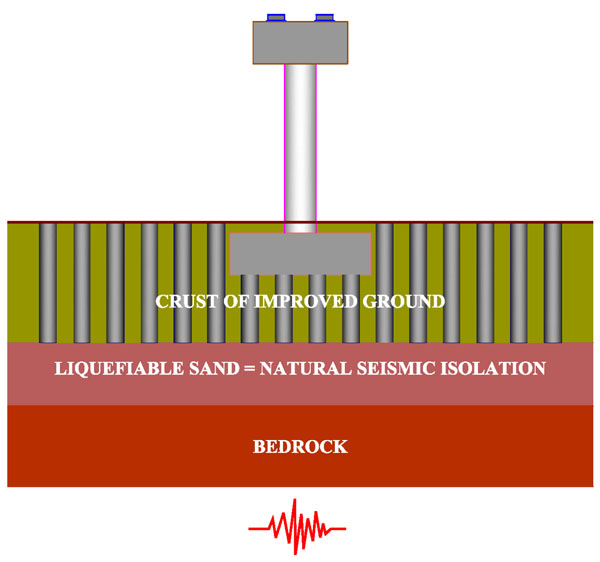
2. ALTERNATIVE FOUNDATION METHOD
As already mentioned the use of shallow foundation for structures resting on liquefiable soil is avoided in engineering practice. Thus, deep foundations are employed ensuring adequate safety, while, along with measures for improvement of the liquefiable soil layer, the overall construction cost increases significantly. Motivated by the latter, the scientific community has been investigating an alternative foundation method, graphically demonstrated in Fig. (1). This involves the use of shallow foundation resting on a non-liquefiable layer, denoted as “crust”, with sufficient thickness and shear strength that assures adequate safety in terms of bearing capacity of the foundation surface during and after a seismic excitation. The underlying liquefiable susceptible layer is intentionally allowed to liquefy, acting as natural seismic isolation. The main effect of this system is to reduce drastically the intensity of seismic motion at the surface of the liquefiable layer leading to the decrease of the inertia forces acting on the superstructure [26-29]. A decisive factor for the implementation of the new foundation method is the thickness of the “crust”, as there is a critical thickness beyond which failure takes place within the crust [8].
3. MATERIAL AND METHODS
3.1. Case Study Description
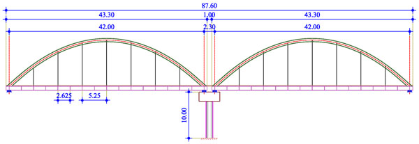
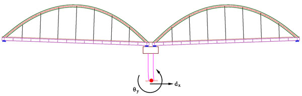
The bridge under investigation is a steel arched road bridge with composite deck consisting of two simply supported spans. An elevation view of the bridge including the two spans and the pier is given in Fig. (2). The total length of the superstructure is 87.60m while the theoretical length of each span is 42.00m. The connection between the two spans is realized by a continuous concrete slab with length equal to 1.00m.
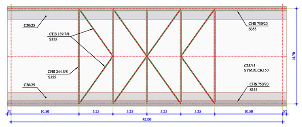
The total width of the composite deck is equal to 15.00m. The steel members of a superstructure span include two (2) main beams with their in-between distance equal to 14.70m and seventeen (17) transverse beams placed at a distance of 2.625m. Each main beam is suspended by the corresponding arch with the use of seven (7) hangers. The two arches are connected with k-type bracings consisting of five (5) transverse and eight (8) diagonal members (Fig. 3). The properties of all steel members are presented in Table 1 including the cross sections as well as the theoretical length and span of each group. Steel grade S355 is employed for all steel members. The composite deck, with total thickness of 35cm, is formed by a concrete slab on trapezoidal profiles, connected with the transverse and main beams through steel shear connectors. The concrete grade used for the slab is C35/45.
| Type | Total Number | Cross Section | Length of Members | Theoretical Span/Rise |
|---|---|---|---|---|
| Main Beams | 4 | HEB900 | 43.30m | 42.00m |
| Transverse Beams | 34 | HEB900 | 14.30m | 14.70m |
| Arches | 4 | CHS750/20 | 47.70m | 42.00m / 10.00m |
| Transverse Bracing Members | 10 | CHS244.5/8 | 13.95m | 14.70m |
| Diagonal Bracing Members | 16 | CHS139.7/8 | 8.45m | 9.13m |
| Hangers | 28 | CHS168.3/8 | 3.90m – 9.625m | 4.375m – 10.00m |
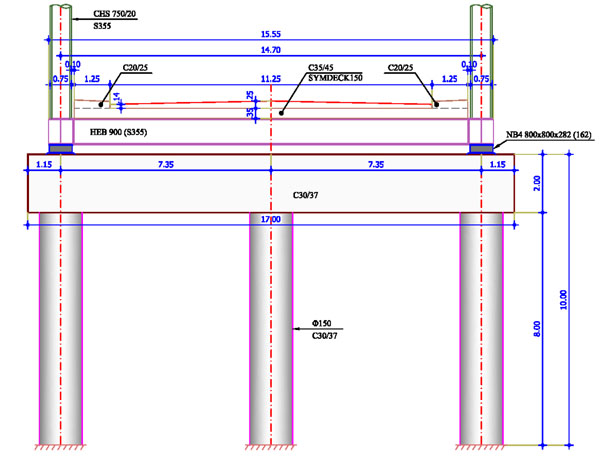
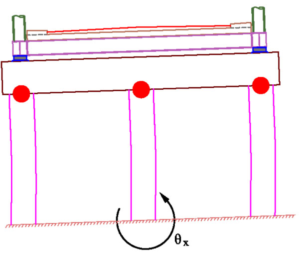
The pier consists of three reinforced concrete columns, 8.00m tall, having circular cross section with diameter equal to 1.50m. The distance between the three columns is 7.35m and they are connected at their top by a concrete beam, 17.00m long, with a rectangular cross section (4.50mx2.00m). The total height of the pier is 10.00m. A transverse view of the pier is illustrated in Fig. (4). For all pier elements, concrete C30/37 with reinforcement of steel grade B500C is employed. Anchored elastomeric bearings of type ΝΒ4 800x800x282(162) are considered for the connection of the superstructure with the pier and the abutments. The abutments are assumed to be seated on stable soil, providing firm foundation ground to the superstructure. They are not included in the model, but they are substituted by pinned supports at the base of their bearings.
3.2. Deformation Limits
Limiting values of various types of displacements are generally not directly associated with certain limit states of the structure. Thus, only simplified approaches are possible. Most researchers [30-32] support the view that settlements less than 5cm are tolerable or acceptable; which could constitute a performance criterion for the Serviceability Limit State (SLS). The same value is also suggested by EN1997-1 in Annex H [33]. Furthermore, settlements larger than 6cm could cause severe structural damage, while settlements up to 10cm are harmful, thus intolerable. This could correspond to an Ultimate Limit State (ULS) condition.
Assuming that the settlement of the abutment is practically zero, limiting values of differential settlements will correspond to the allowable vertical displacement of the pier. AASHTO [34, 35] sets a limit of 0.008rad in the allowable angular distortion of simply supported bridges. Taking into account that the span between the pier and the abutment of the bridge under study is 42m, the aforementioned value corresponds to a differential settlement of 33.6cm between the pier and the abutments. It should be mentioned that the angular distortion is defined as the ratio of the differential settlement between two consecutive foundations over the span length. Moulton et al. [36], instead, set a limit in the allowable angular distortion equal to 0.005rad, which, in case of this bridge, corresponds to 21cm. Finally, according to EN1997-1 [33], a limiting value of 0.002rad is set in the allowable angular distortion of such structures for Serviceability Limit State corresponding to 8.4cm of differential settlement, while, for Ultimate Limit State, a limiting value of span/150 is proposed. Applying the Eurocodes in this study, maximum allowable settlements for the Serviceability Limit State should not exceed 8.5cm, while for the Ultimate Limit State the limit arises at 28cm.
In ULS, according to several researchers [30, 31] and [36], horizontal displacements up to 2.5cm are considered tolerable, values between 2.5cm and 5cm are harmful, while displacements larger than 5cm could cause structural damage, thus are defined as intolerable. Moulton et al [36] suggested that the value of horizontal displacement of the pier footing equal to 38mm could constitute a performance criterion for the SLS condition. In case the horizontal displacement coexists with settlement, the tolerable value is 25mm.
Regarding the studied bridge the most critical structural member is the pier, which essentially dictates the tolerance of the entire system to liquefaction-induced deformations. In this system, where the pier is a simple cantilever in the longitudinal direction of the bridge, when longitudinal displacements or rotations in the transverse direction of the bridge prevail, the formation of plastic hinges at its base is not allowed, since the structural system becomes a mechanism, unable to carry even the vertical loads (Fig. 5). Moreover, when rotations about the longitudinal axis are dominant, the pier of the bridge under investigation acts as a statically indeterminate frame, thus, the formation of plastic hinges is allowed at the top of its columns (Fig. 6). Hence, the maximum permissible ground settlement and rotations correspond to the first yield at the pier base, or the formation of plastic hinge at the top of the pier, or the plastic resistance of the steel members, whichever occurs first.
3.3. Nonlinear Analyses
3.3.1. Numerical Model
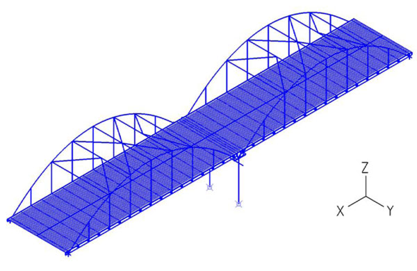
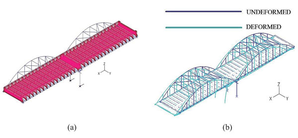
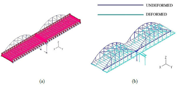
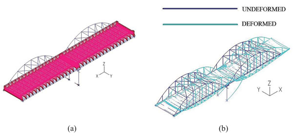
In order to simulate the behaviour of the arched steel road bridge imposed to differential displacements and rotations, a numerical model using the finite element analysis software ADINA [25] is developed. Geometric and material nonlinearities are taken into account. For the configuration of the numerical model, three different types of finite elements are employed. Beam elements are used for the modelling of the main beams, the secondary beams, the arches, the transverse bracing members and the structural elements of the pier (columns and concrete beam). Truss elements simulate the diagonal bracing members and the hangers. Regarding the concrete slab, shell elements with a thickness of 25cm, accounting for the mean value of the total thickness, are selected. The numerical model of the bridge is illustrated in Fig. (7).
The connection of the slab through bearings with the abutments and the pier are simulated by horizontal and vertical equivalent nonlinear springs. As the abutments are not modelled in the present study, the corresponding springs are considered fixed at their base. The initial stiffness of each spring imposed to horizontal and vertical displacements is calculated according to EN1337 [37, 38] and EN1998 [39].
3.3.2. Material Laws
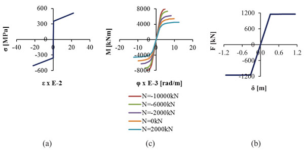
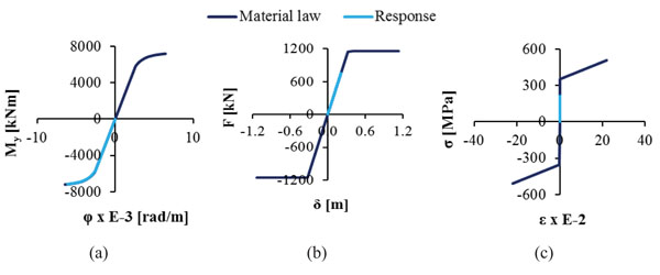
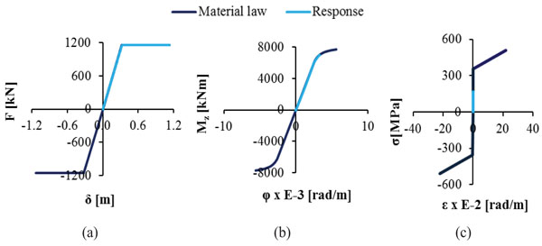
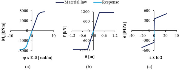
Nonlinear analyses are conducted taking into account the geometric and material nonlinearity through their constitutive laws. The material law of structural steel S355 is depicted in Fig. (8a) according to the codes [40-42]. The nonlinear behaviour of the columns of the pier is modelled by means of Μoment-curvature (M-φ) diagrams, shown in Fig. (8b), that have been calculated for characteristic values of axial forces using the software myBiaxial [43-44], assuming that the longitudinal reinforcement of the columns is 45Φ25 placed at equal distances with a cover of 8cm. The maximum and minimum value of the axial force taken into consideration for the Moment – Curvature diagrams equals the strength of the cross section of the pier columns to uniaxial tension and compression, respectively, the values of which are derived by the interaction diagram M-N of the section, calculated by software Response-2000 [45]. The nonlinear behaviour of the horizontal springs, simulating the bearings of the abutments and the pier, is described by the Force-Displacement (F-δ) curve denoting the maximum tolerable displacement of the bearing according to the pertinent codes (Fig. 8c). More specifically, according to EN1998 [39], the shear strain γq,d of the elastomer due to translational movement, defined as the ratio of the maximum resultant horizontal relative displacement of parts of the bearing over the total thickness of the elastomer (γ=δ/t), shall not exceed the value of 2.00, corresponding to a horizontal deformation between the upper and lower surfaces of the bearings equal to δq,d=0.324m. Moreover, the maximum design strain γt,d, defined as the sum of the shear strain due to translational movement γq,d, the design strain due to compressive loads γc,d and the nominal strain due to angular rotation γα,d, shall not exceed the maximum value of 7.00 leading to a maximum horizontal deformation of maxδt,d=1.13m. The horizontal springs that simulate the stiffness of the bearings to horizontal displacements are assumed to have nonlinear behaviour acting linearly up to a horizontal movement of δq,d, while they lose their stiffness if this limit is exceeded but the analysis continues until their horizontal deformation reaches the value of maxδt,d. The stiffness of the horizontal springs is calculated equal to k=3556kN/m, thus the force F of the diagrams is given as F = k · δ. A very large stiffness is assumed for the vertical springs.
3.3.3. Imposed Loads
Three load cases are taken into account: the self-weight (LC1), the superimposed loads including the weight of the pavement and the sidewalks (LC2) and the imposed displacements or rotations at the base of the pier (LC3). More specifically, LC3 describes displacements (dx, dy, ρ) and rotations (θx, θy) applied at the base of each pier column, simulating the liquefaction induced ground movements in case of a seismic event. Each displacement and rotation is imposed separately without taking into account combinations between them. All partial factors are considered equal to one. No live loads are considered, as they act favourably, causing additional compression to the pier, which is the most vulnerable component of the bridge to ground movements.
Special attention is drawn on the modelling of the support at the footing of the pier columns, accounting for a fixed connection. Namely, when LC1 and LC2 are exerted it is considered that the pier columns remain fixed at their base. Nevertheless, as the applied displacements and rotations evolve, the corresponding degrees of freedom are released. To this end, springs with infinite stiffness in the direction of the imposed displacements and rotations are employed that are activated for the first two load cases and deactivated for the last one allowing the movement at the base of the pier to evolve.
3.3.4. Sequence of Imposed Loads
The application of the loads is realized in several time steps, as is common in nonlinear analysis, in order to simulate the real behaviour of the bridge in an accurate way. In particular, from t=0 to t=0.995 the self-weight of the steel structure is applied without taking into account the stiffness of the composite deck. At t=1, the shell elements of the concrete slab are activated while the superimposed loads begin to evolve. The imposition of LC2 (superimposed loads) is completed at t=2 when the springs with the infinite stiffness at the base of the pier are deactivated. From t=2 to t=3, the liquefaction induced movements are applied, taking into consideration the geometric and material nonlinearities of the system. The loading sequence is presented in Table 2.
| Time Period (t) | LC1 | LC2 | LC3 | Surface Elements | Pier Support |
|---|---|---|---|---|---|
| 0 | 0% | 0% | 0% | ̶ | √ |
| 0.995 | 100% | 0% | 0% | ̶ | √ |
| 1 | 100% | 0% | 0% | √ | √ |
| 2 | 100% | 100% | 0% | √ | ̶ |
| 3 | 100% | 100% | 100% | √ | ̶ |
3.3.5. Method of Analysis
Nonlinear static analyses are performed and the response of the pier columns, the steel elements and the elastomeric bearings due to imposed ground movements is monitored until the first failure occurs. Then, the maximum tolerable displacements and rotations at the footing of the pier are detected and the behaviour of the crucial bridge components is assessed comparing their response with the corresponding material laws. The response of the structural members, which are deemed easily repairable or replaceable, such as the continuous slab and the expansion joints, is not considered to be crucial for the definition of the tolerable movements at the foundation of the pier, as they cannot cause a total failure of the bridge. Although the bearings are considered replaceable, their stiffness is reduced in case they fail and the response of the whole bridge is affected. This eventual change of their stiffness is taken into account in the analysis, through their material law.
4. RESULTS
4.1. Tolerable Displacements and Rotations of the Pier
The sensitivity of the bridge to imposed displacements and rotations with respect to the global axes is investigated in this section and the permissible limits are defined.
4.2. Response of the Bridge to Induced Ground Displacement dx
The vertical loads in combination with the ground displacement about the longitudinal axis x, as well as the corresponding deformed structure, are presented in Fig. (9). The maximum displacement dx reaches the value of 0.52m at t=2.99 and flexural failure occurs at the base of the outer pier columns. Nevertheless, the first yield of the pier columns occurs at t=2.75 when the horizontal displacement becomes 0.40m. As already explained, for longitudinal movements the pier is considered as cantilever and no plastic hinges are allowed at its base, thus the maximum permissible displacement for the bridge is considered equal to 0.40m that causes the first yield to the middle column of the pier.
At the last time step of the nonlinear analysis, the magnitude of the developed axial force at the footing of the columns is calculated, the M-φ diagrams are plotted for all columns of the pier, and the response of all critical bridge components is compared with the corresponding material laws. The behaviour of the bridge to horizontal ground displacement is represented by the three representative diagrams of Fig. (10), describing the response of the most critical column of the pier at the point of the first hinge creation, the bearings and the main beams, which develop the maximum stress among the steel members of the superstructure. In Fig. (10a) the bending moment My of the pier column is plotted, referring to the local axis y, which is parallel to the global Y-axis. The pier columns prove to be the most vulnerable elements for this ground movement, exhausting their capacity first among all other components of the bridge, whereas the springs simulating the elastomeric bearings and all the steel members remain elastic.
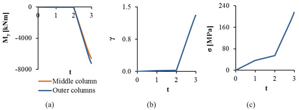
The developed internal forces and deformations of the characteristic bridge members are illustrated in Fig. (11) as functions of the time of the imposed loads. It can be observed that the pier columns develop significant internal bending moments through the imposition of the longitudinal displacement dx (from t=2 to t=3), while the vertical loads do not induce bending (from t=0 to t=2). Regarding the springs simulating the bearings, significant shear deformations are developed, when the displacement dx is exerted at the footing of the pier (from t=2 to t=3), without though leading to their failure. The main beams are influenced by the imposition of the longitudinal displacement developing stress equal to 220MPa that does not exceed the yield stress.
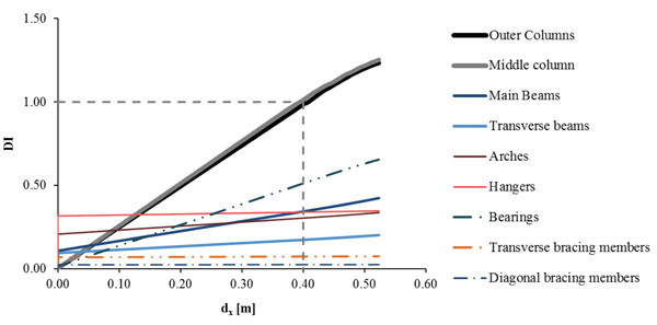
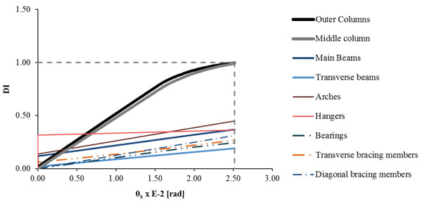
A Damage Index (DI) is used for each component of the bridge, defined as DI=Ed/Rd. Ed is the calculated response of the bridge by means of the maximum bending moment of the pier columns, the maximum stress for the steel members and the maximum strain for the bearings the moment of the first yield for the columns of the pier. Rd is the magnitude that defines the strength of each component, namely the yielding bending moment of the pier columns with respect to the developed axial force derived from the M-φ diagrams, the ultimate stress fu=510MPa for the steel members and the limit of the maximum shear strain γq,d=2 for the bearings, as the translational movement prevails. The evolution of damage is illustrated in Fig. (12) by means of the DI for the whole analysis up to first failure, where it is shown that DI for the pier columns increases continuously, while the bearings exhaust only half of their capacity at failure. All other components of the bridge are slightly affected by the ground horizontal displacement dx. At first yield, the horizontal displacement takes the value of 0.40m and the DI of the pier columns becomes equal to 1, defining the design limit for the induced ground horizontal longitudinal displacement. The maximum value of DI is 1.25, accounting for the formation of the first plastic hinge at the outer columns of the pier. The results corresponding to the design limit of the displacement dx=0.40m are summarized in Table 3, giving the maximum response of each component of the bridge, with respect to the strength and their DI.
| Structural Members | Response (Ed) | Strength (Rd) | DI (Ed/Rd) |
|---|---|---|---|
| Pier Columns | 5255kNm | Bending Moment 5207kNm | 1.00 |
| Main Beams | 175MPa | Ultimate Stress 510MPa | 0.34 |
| Transverse Beams | 88MPa | 0.17 | |
| Arches | 155MPa | 0.30 | |
| Transverse Bracing Members | 37MPa | 0.07 | |
| Diagonal Bracing Members | 12MPa | 0.02 | |
| Hangers | 173MPa | 0.34 | |
| Bearings | 1.02 | γq,d = 2 | 0.51 |
4.3. Response of the Bridge to Induced Ground Displacement dy
In this case, the sum of the vertical loads and the displacement in the transverse direction of the bridge are considered (Fig. 13a). The deformed geometry of the structure is presented in Fig. (13b), where it can be observed that the bearings of the pier develop significant translational deformations, being thus the most vulnerable components of the bridge. The nonlinear analysis stops at t=2.89, when the displacement dy is equal to 2.32m, as the bearings of the pier are not capable to sustain the increased transverse displacement. However, the maximum shear strain of the bearings is reached at t=2.28 for a ground displacement dy equal to 0.72m, which constitutes the design limit for this ground movement. After this value the system deforms without resistance, as the connection of the deck with the pier is lost due the annihilation of the bearings stiffness.
The comparison between the response of the critical components of the bridge and their corresponding material laws is illustrated in Fig. (14). It is noted that first the springs, modelling the bearings of the pier, reach failure due to translational movement, whereas the pier columns exceed their elastic limit, without though corresponding to failure, as the pier in the transverse direction forms a frame and the creation of the plastic hinges is permitted. The bending moment Mz of Fig. (14b) refers to the local axis z of the pier columns, which is parallel to the global X-axis. Among the steel members, the maximum stress is calculated at the hangers, which is equal to 167MPa, remaining though in the elastic zone. The diagrams describing the developed internal forces with respect to time are plotted in Fig. (15). It is noted that the members of the bridge such as the pier columns and the hangers develop stress until t1=2.28, when the stiffness of the springs becomes zero, while after that time the pier moves independently without resisting the imposed transverse displacement.
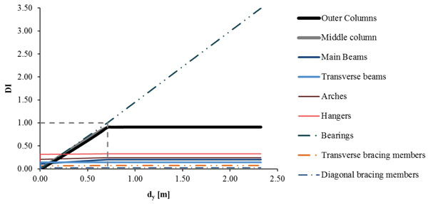
Summarizing the results for all bridge components, the DI is calculated and the evolution of the damages is shown in Fig. (16) by means of the DI for the whole analysis. It is noted that the bearings first lose their stiffness as the shear strain exceeds its limit and then they reach total failure. The DI for the pier columns increases until the stiffness of the bearings becomes zero, reaching a value of DI=0.91. All other bridge components are not influenced significantly by the horizontal ground displacement dy, remaining in the elastic zone. When the stiffness of the bearings becomes zero, the horizontal displacement takes the value of 0.72m and the DI of the bearings becomes equal to 1, setting the design limit for the induced horizontal transverse ground displacement. The maximum value of the DI is 3.50, accounting for the failure of the bearings. The results corresponding to the design limit of the displacement dy are given in Table 4, by means of the maximum response of each component of the bridge with respect to the strength and their DI.
| Structural Members | Response (Ed) | Strength (Rd) | DI (Ed/Rd) |
|---|---|---|---|
| Pier Columns | 6008.80kNm | Bending Moment 6584.32kNm | 0.91 |
| Main Beams | 104MPa | Ultimate Stress 510MPa | 0.20 |
| Transverse Beams | 73MPa | 0.14 | |
| Arches | 125MPa | 0.25 | |
| Transverse Bracing Members | 38MPa | 0.07 | |
| Diagonal Bracing Members | 13MPa | 0.03 | |
| Hangers | 167MPa | 0.33 | |
| Bearings | 2 | γq,d = 2 | 1.00 |
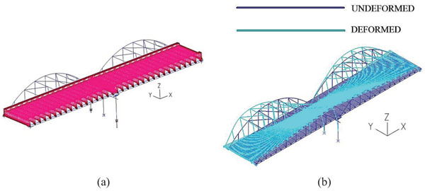
4.4. Response of the Bridge to Induced Settlement ρ
Next, the behaviour of the bridge to imposed settlement due to soil liquefaction is studied. After the imposition of the superimposed loads (t=2), vertical forces equal to the corresponding reactions are exerted at the base of the pier columns. The magnitude of the aforementioned forces is decreased gradually, allowing the settlement of the bridge. The analysis stops at t=3.00, when the settlement of the pier reaches the value of 2.58m, due to large rotational deformation of the bearings. The applied loads and the deformed geometry of the bridge are depicted in Fig. (17), showing large inclination of the deck due to the pier settlement. In such case severe damage occurs at the continuous slab connecting the two spans. However, as it is considered replaceable, its large deformations do not indicate an overall bridge failure. Nevertheless, for such large settlements the shear deformation of the bearings is significant, reaching to failure. The maximum tolerable settlement is 2.58m that is considered quite high and cannot constitute a design criterion. At that time, it is certain that the bridge would have lost its serviceability due to the failure of the continuous concrete slab and the large inclination of the deck. According to EN1997-1 [33], as already mentioned, the maximum allowable settlement is equal to 28cm.
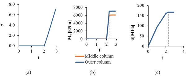
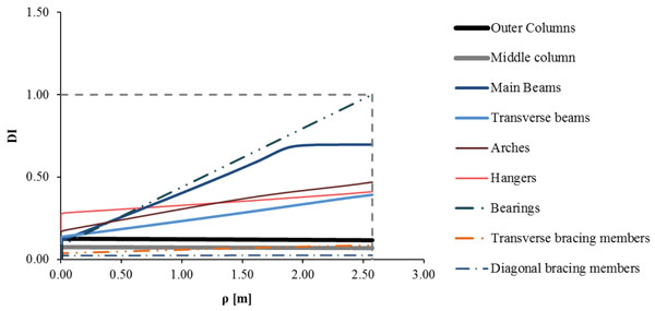
Such settlement causes significant rotation of the bearings about the transverse axis of the bridge, while their translational movement is negligible. The diagram of the angular rotation φy of the abutments’ bearings presenting the maximum total strain γ is plotted in Fig. (18a), showing that at the end of the analysis the total strain reaches the value of the maximum design strain equal to 7, as defined in section 5.2. The columns of the pier do not develop significant additional internal forces due to the settlement, as they move vertically without resisting, being thus the less vulnerable components of the bridge for this kind of ground movement. The main beams are the most critical steel members of the superstructure developing the largest stress, due to increased tension forces and bending moments at their ends. The maximum stress of the main beams at the end of the analysis is equal to 356MPa, slightly exceeding the yield stress, as plotted in Fig. (18b) along with the material law. The DI is calculated for all components of the bridge and the evolution of the damages is plotted in Fig. (19) by means of these indices, while the results of the analysis are listed in Table 5. It is noted that the bearings first lose their stiffness as the angular rotation increases rapidly and the total strain reaches the design limit of 7, defining the failure of the bearings. The main beams show an increasing DI until they reach the yield stress taking the value of 0.70, but entering in the plastic zone their DI remains almost unaltered. All other steel members of the bridge are represented by DI smaller than 0.50, corresponding to low damage levels. The DI for the columns of the pier is defined by the ratio of their axial force over the maximum pure compressive force they can sustain, as the bending moments are negligible.
| Structural Members | Response (Ed) | Strength (Rd) | DI (Ed/Rd) |
|---|---|---|---|
| Pier Columns | 4534.86kN | Compressive Force 39000kN | 0.12 |
| Main Beams | 356MPa | Ultimate Stress 510MPa | 0.70 |
| Transverse Beams | 200MPa | 0.39 | |
| Arches | 239MPa | 0.47 | |
| Transverse Bracing Members | 43MPa | 0.09 | |
| Diagonal Bracing Members | 13MPa | 0.02 | |
| Hangers | 210MPa | 0.41 | |
| Bearings | 7 | γt,d = 7 | 1.00 |
4.5. Response of the Bridge to Induced Ground Rotation θx
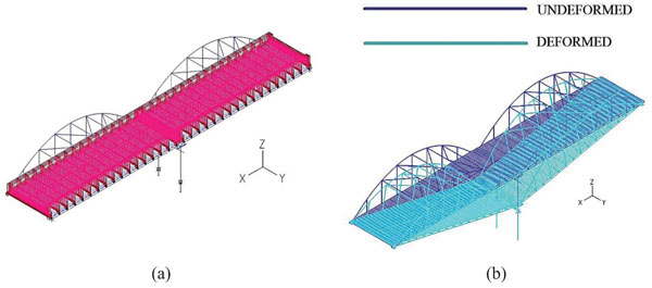
Rotation along the longitudinal axis x is applied at the base of the pier columns, in combination with the sum of the superimposed loads, as illustrated in Fig. (20a). The application of rotation θx is realized by imposing vertical forces at the base of the outer pier columns that are equivalent to the developed reaction forces at t=2. From t=2 to t=3, the magnitude of one vertical force is increased whereas the value of the other is decreased, allowing the rotation of the bridge about the longitudinal axis x. The nonlinear analysis stops at t=2.99, when θx=0.025rad, due to bending failure at the top of the outer pier columns. The deformed state at the moment of failure is depicted in Fig. (20b).
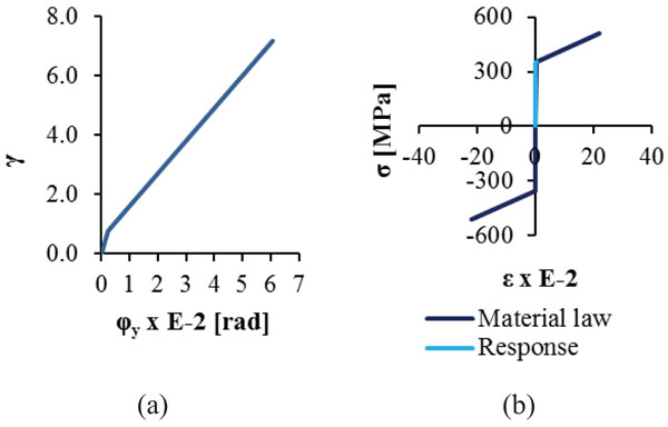
Due to the imposed rotation θx the pier acts as a frame, hence significant bending moments develop at the top of its columns, leading to the creation of plastic hinges defining flexural failure. The M-φ diagrams are plotted in Fig. (21a), where it is noted that the columns exhaust their capacity. Regarding the bearings, the load-displacement diagram of the horizontal springs in the transverse direction is illustrated in Fig. (21b), where it is noted that they behave elastically until the end of the analysis. The maximum stress-strain diagram for the arches is given in Fig. (21c) in comparison with the material law. The arches present the maximum stress among the steel members of the bridge, equal to 229MPa that corresponds to 90% of the yield stress. Monitoring the response of all components of the bridge the evolution of the DI is calculated and shown in Fig. (22) for the whole time of analysis. It is noted that this index increases continuously for the pier columns until it reaches the value of 1 accounting for failure, while the DI for the bearings and the steel members remain below 0.50, indicating elastic behaviour. The results corresponding to the design limit of rotation θx are given in Table 6 by means of the maximum response of each component of the bridge with respect to the strength and their DI.
| Structural Members | Response (Ed) | Strength (Rd) | DI (Ed/Rd) |
|---|---|---|---|
| Pier Columns | 7649.52kNm | Bending Moment 7647.83kNm | 1.00 |
| Main Beams | 187MPa | Ultimate Stress 510MPa | 0.38 |
| Transverse Beams | 98MPa | 0.19 | |
| Arches | 229MPa | 0.45 | |
| Transverse Bracing Members | 137MPa | 0.27 | |
| Diagonal Bracing Members | 159MPa | 0.31 | |
| Hangers | 185MPa | 0.36 | |
| Bearings | 0.485 | γq,d = 2 | 0.24 |
4.6. Response of the Bridge to Induced Ground Rotation θy
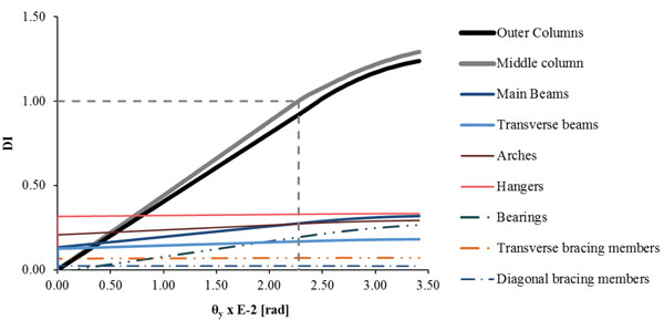
Rotation about the transverse axis y, combined with the sum of the vertical loads, is exerted at the base of the pier columns, as indicated in Fig. (23a). The analysis stops at t=2.98 due to bending failure at the base of the outer pier columns. The maximum developed rotation θy is 0.034rad and the deformed geometry of the bridge is illustrated in Fig. (23b). It is observed that the current deformed state is similar to the corresponding deformed geometry of ground horizontal displacement dx shown in Fig. (9b). The main difference between these two situations is based on the fact that during the imposition of displacement dx the pier columns are allowed to move in the longitudinal direction, whereas through the exertion of the rotation θy they are considered fixed at their base in the horizontal direction. Through the imposition of the rotation about the transverse axis the pier behaves as cantilever, developing significant bending moments at the base of its columns. In such a case, as already explained, no plastic hinges are allowed, and the maximum permissible rotation about the transverse axis of the bridge is defined by the first yield, which occurs at the base of the middle column at t=2.65 when the ground rotation θy takes the value of 0.023rad.
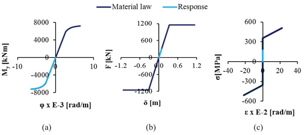
The Moment – Curvature diagram at the base of the outer pier columns is illustrated in Fig. (24a) denoting that at the end of the nonlinear analysis the pier columns reach failure at their base. Comparing the response of the bearings of the pier with their material law, it is concluded that they remain in the elastic zone until the end of the analysis, as shown in Fig. (24b). The maximum stress-strain diagram for the hangers developing the maximum stress among the steel members of the bridge is illustrated in Fig. (24c), which takes the value of 170MPa, remaining below the yield stress. The evolution of the DI is plotted in Fig. (25) until the analysis stops and the first failure occurs. The DI for columns of the pier increases continuously, while for all other components of the bridge it remains below 0.35, meaning that they are only slightly affected by the ground transverse rotation θy. At first yield, the ground rotation takes the value of 0.023rad and the DI of the middle pier column becomes equal to 1, defining the design limit for the imposed transverse ground rotation. The maximum value of the DI is 1.29, accounting for the time of the first plastic hinge creation at the outer columns of the pier. The results corresponding to the design limit of rotation θy are listed in Table 7, by means of the maximum response of each component of the bridge, with respect to the strength and their DI.
| Structural Members | Response (Ed) | Strength (Rd) | DI (Ed/Rd) |
|---|---|---|---|
| Pier Columns | 5075.91kNm | Bending Moment 5068.24kNm | 1.00 |
| Main Beams | 140MPa | Ultimate Stress 510MPa | 0.28 |
| Transverse Beams | 86MPa | 0.17 | |
| Arches | 139MPa | 0.27 | |
| Transverse Bracing Members | 36MPa | 0.07 | |
| Diagonal Bracing Members | 11MPa | 0.02 | |
| Hangers | 168MPa | 0.33 | |
| Bearings | 0.39 | γq,d = 2 | 0.19 |
5. DISCUSSION
5.1. Final Results
All results from the analyses conducted for the arched steel bridge are summarized in Table 8. The ground movements that are found to be most critical are the ones that cause large bending moments at the base of the pier columns, namely horizontal displacement dx and rotation θy. In this case study, the design criterion defining the maximum tolerable ground movement dictates that no plastic hinges should be created at the base of the pier, as it is considered to be a cantilever system, leaving though some margins until the formation of the hinges which will lead to total collapse.
| Ground Induced Movement | Structural Member | Maximum Value | Allowable Limit [33] |
|---|---|---|---|
| Displacement dx | Pier Columns (Base) | 0.40m | - |
| Displacement dy | Bearings | 0.72m | - |
| Settlement ρ | Bearings | 2.58m | 0.28cm |
| Rotation θx | Pier Columns (Top) | 0.025rad | - |
| Rotation θy | Pier Columns (Base) | 0.023rad | - |
For this bridge system, consisting of two simply supported spans, the settlement is not as critical as the horizontal displacements and rotations, causing only damage at the connection slab of the deck and large rotations at the bearings, which are both repairable and replaceable. The permissible limit for settlement is set by the Eurocodes, which, as mentioned in section 4, is equal to 28cm. It is certain that such limit does not cause any damage in the structural components of the bridge, as shown in section 6.3 and more specifically in Fig. (19). Nevertheless, combining this value with a ground rotation or a horizontal displacement, as usually occurs in a liquefaction phenomenon, the limits of Table 8, regarding these predominant ground movements, will be reduced. A combination of the ground movements in all directions should be taken into consideration in the final design of the bridge [46-48]. For example, in [48] a relation between the rotation and the settlement is proposed, expressed as θ=0.05ρ, where the rotation θ at the pier footing is in degrees, while the uniform settlement ρ in cm. This means that the permissible rotation θy, which is the smallest value among the rotations, equal to 0.023rad (=1.32o), should be combined with a settlement equal to 26cm. This value is much smaller than the maximum tolerable settlement of 2.58m calculated in section 6.3. The bridge remains almost intact to such a vertical displacement, thus, a ground movement combination does not alter significantly the permissible rotations of Table 8.
It should be mentioned that buckling of steel members was taken into account for their dimensioning and final selection of their cross sections at ULS. In all cases of ground movement studied in this work, the arches, which are the main compressive steel members of the superstructure, develop axial forces almost half of the ones calculated at ULS and almost one third of their design buckling resistance. All other members develop stresses much smaller than the arches, thus they are not considered to be susceptible to buckling. Hence, as loss of buckling resistance is not expected for the members of the superstructure due to liquefaction movements, for simplicity buckling of steel members is neglected at this preliminary design stage.
The allowable limits of ground movements, derived by the procedure presented herein, are used for the preliminary design of the pier spread footing and the dimensions of the “crust”. The final design of the bridge should include the entire model of the bridge with the pier foundation and appropriate springs and dashpots simulating the soil-foundation-structure interaction effects for the static and dynamic response of the bridge, taking also into account the particular stratification of the subsoil. The permanent loads, live loads, seismic action and a combination of initial imperfections to ensure the stability of the steel members against buckling should be considered in this final design stage.
CONCLUSION
The bridge under investigation is a steel arch road bridge with two simply supported spans, with a middle pier consisting of three circular reinforced concrete columns connected at their top with a concrete beam, forming thus a frame in the transverse direction of the bridge, and at their base with a common spread footing. In this study the footing is not simulated. Instead, fixed supports are considered at the base of the columns. The bridge is supposed to be seated on a layer of non-liquefiable “crust” lying over a liquefaction susceptible soil. Additional permanent ground movements, by means of horizontal displacements, settlement and rotations may occur after a major earthquake event. The behaviour of the bridge is investigated in order to determine the permissible ground movements without loss of its serviceability and resistance setting the allowable limits of the preliminary design of the pier footing and dimensioning of the “crust”.
The design criteria set in this study specify that for the assumed pier system plastic hinges at the base of the columns are not allowed, because they would lead to the collapse of the bridge. The analyses showed that the pier and bearings are the most vulnerable components of the bridge. Failure occurs at the bearings only in case of ground transverse displacement and settlement, while all other ground movements cause failure at the pier columns. As expected for a simply supported bridge, the settlement itself does not constitute a critical limit, but in combination with rotations or/and horizontal movements could define a design criterion for the foundation of the bridge.
CONSENT FOR PUBLICATION
Not applicable.
CONFLICT OF INTEREST
The authors declare no conflict of interest, financial or otherwise.
ACKNOWLEDGEMENTS
The work presented here was carried out in the framework of research program “Innovative design of bridge piers on liquefiable soils with the use of natural seismic isolation”, having Professor George Bouckovalas as principal investigator. This research has been co-financed by the European Union (European Social Fund - ESF) and Greek National funds through the Operational Program “Education and Lifelong Learning” of the National Strategic Reference Framework (NSRF) – Research Funding Program: THALES: Reinforcement of the interdisciplinary and/or inter-institutional research and innovation.

