All published articles of this journal are available on ScienceDirect.
Nonlinear Behaviour of Mid-rise Steel Buildings with Gate Braced Frames
Abstract
Off-center or gate braced frames are a special configuration of inverted V bracing with non-straight diagonal members that are made of two elements connected to the corner of the frame by another member. This arrangement is characterized by an eccentricity of the intercepted bracing as respect to the straightness of the theoretical working length of the diagonal members in chevron configuration. These types of braced frames permit larger openings with significant advantages in terms of architectural functionality. The seismic performance of gate braced frames differs from that of traditional chevron braced frames, because of the out-of-straightness eccentricity of bracing members and the position of the corner-to-brace connecting element. Therefore, in this paper, a numerical parametric study based on both nonlinear static pushover and dynamic time-history analyses is presented and discussed in order to examine the influence of brace-to-brace detailing on seismic response of this structural typology. The results showed that the initial stiffness, the strength and the interstorey drift demand are very sensitive to the out-of-straightness eccentricity of bracing.
1. INTRODUCTION
Concentrically braced frames (CBFs) are commonly used in multi-storey steel building to provide lateral strength and stiffness against both seismic and wind forces. Different arrangements of CBFs are possible depending on the orientation of diagonal members, such as single diagonal, X-brace, chevron, and two story X-brace. Extensive research has been also conducted on seismic performance of these types of CBFs [1-11], which aimed at improving both code requirements and assessment procedures. However, in the framework of Eurocode 8 [12] little attention has been paid to support the design of other concentrically bracing configurations such as off-center or gate CBFs.
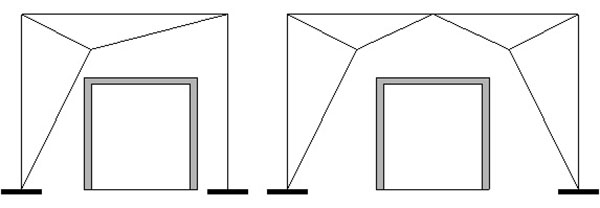
Recently, there is an increasing interest on this type of CBF as primary seismic resisting system in low and medium rise steel buildings. Indeed, one of the main advantages of gate CBFs over the other bracing shapes is the possibility to provide larger door or window openings. As depicted in Fig. (1), two different configurations are possible for gate CBFs. The first configuration consists of three members [13-16], while six members in the second one [17, 18]. Both arrangements have non-straight diagonal members that are connected to the corner of the frame by another element, thus resulting in eccentricity with respect to the theoretical working length of the straight diagonals. This eccentricity is the key design parameter, which allows controlling the strength, the stiffness and the hysteretic response of the system [19]. However, due to the brace-to-beam interaction in the configuration with six members, the design provisions and the expected inelastic performance differ with the gate bracing arrangement.
In the literature, the load-deflection characteristics and nonlinearity due to eccentricity of this bracing system on the steel frames were investigated by Moghaddam and Estekanchi [13] and Estekanchi et al. [19]. On the basis of the acceleration response spectra under earthquake ground motion, Rasekh et al. [14] suggested that off-center braced frames can effectively perform as hysteretic seismic isolation systems. Bazzaz et al. [15] carried out finite element analyses on three steel frames with different eccentricities in order to obtain the optimum brace eccentricity. Yazdi et al. [20] proposed a method based on the multi-objective genetic algorithm to suggest the appropriate location of brace-interception point. In the study of Fanaie and Ezzatshoar [18], the overstrength, ductility and response modification factors of steel frames with gate bracing system were critically evaluated, providing also the fragility curves for estimating seismic demands. However, these studies have highlighted that further researches are still needed to characterize the appropriate performance level and to develop corresponding design criteria.
In light with these objectives, the present study aims at investigating the influence of out-of-straightness eccentricity on the seismic response of a mid-rise steel frame equipped with gate bracings. With this regard, a parametric numerical study based on nonlinear static pushover and dynamic time history analyses was carried out on a case study structure varying the out-of-straightness eccentricity of bracing. The response was evaluated and discussed comparatively in terms of maximum inter-storey drift, roof drift, distribution of storey drift, displacement-time history, hysteretic behaviour, and damage distribution.
2. FRAMEWORK OF THE STUDY
2.1. Investigated Parameters
The key geometric parameters affecting the lateral response of gate braced frames are the out-of-straightness eccentricities of diagonal bracings e1 and e2, which are defined according to [21] as shown in Fig. (2). The eccentricity e1 represents the deviation of the tension strut BOC from the diagonal BC and e2 defines the position of the projection of O on the theoretical working length of the straight diagonal BC. It should be noted that e1 is the parameter that mostly influences the nonlinear effects under lateral loading as reported in the study of Rasekh et al. [14]. Indeed, once the load is applied, the three members constituting the equivalent diagonal element in tension are stretched, while those constituting the equivalent compression diagonal element buckle. As the interstorey drift ratio demand increases, the original geometry substantially changes.
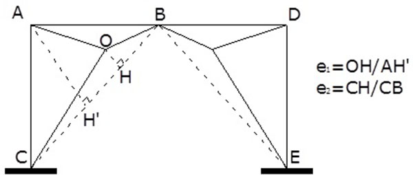
Due to geometrical and technological aspects (e.g. the span to interstorey height ratios, dimension of gusset plates, etc.) the eccentricity e2 does not significantly vary. On the contrary, e1 may substantially vary. Therefore, in the present study, e2 was taken constant and equal to 0.56, while the examined values for e1 were 0.1, 0.2, 0.4, 0.6, 0.8, and 0.9.
2.2. Description of Case Study and Modelling Assumptions
A symmetric four storey steel building with a square plan of three bays was designed to investigate the seismic performance of gate bracing. Fig. (3) shows the typical floor plan, and elevation of the case study structure.
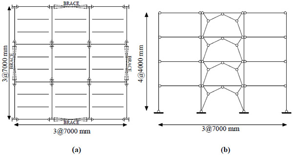
The gate bracing were located along the perimeter in the central span of each side of the plan. The remaining parts of the structure were designed to resist gravity loads only. Therefore, simple shear connections constitute the beam-to-column assemblies. At each floor, the rigid diaphragm transmitting the horizontal actions is made of composite slabs with profiled steel sheetings supported by the hot rolled “I-shaped” beams; the composite action is obtained for all beams by applying shear connectors between the slab and the beams. The secondary beams were placed at about 2.3 m among the main girders.
The structure was designed using concept “DCH” (Ductility Class High) according to EN1998-1 [12] a reference peak ground acceleration equal to agR = 0.35g (being g the gravity acceleration) and a soil type A, a type 1 spectral shape and a behaviour factor q=2.5. The design live and additional dead loads for the building were taken as 2 kN/m2 and 4 kN/m2, respectively. S275 steel grade was used for columns and beams, while S235 for brace members. The members resulting from design procedure are reported in Table 1.
| Story | Column | Beam | Brace |
|---|---|---|---|
| 1 | HE550B | HE550M | 2UPN300/12 |
| 2 | HE450B | HE500M | 2UPN280/12 |
| 3 | HE340B | HE450M | 2UPN260/12 |
| 4 | HE240B | HE320M | 2UPN240/12 |
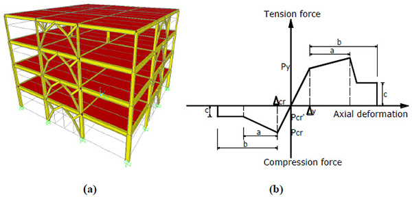
Fig. (4a) shows one of the numerical models that were developed by using the finite element program of SAP 2000 ver. 14.0 [22]. The nonlinear response of members was simulated by means of lumped plasticity approach. The hysteretic relationships of plastic hinges were based on the multilinear response curve given by FEMA-356 [23]. Plastic hinges were assigned at both ends of columns and at the interception with bracing for beams, while at the midpoint of each element for all bracings, whose force-deformation relationship is shown in Fig. (4b).
Table 2 reports the natural periods and effective mass percentages (UX and UY) for the three main modes of vibration obtained varying the eccentricity e1. As it can be observed, the smaller is the bracing out-of-straightness (i.e. smaller e1) the stiffer is the structure, which tends to behave in elastic range (namely when both diagonals are active) as a traditional chevron braced frames. On the contrary, the larger values of out-of-straightness lead to increase the deformability of the structure, which tends to behave in elastic range as a sort of moment resisting frame, where the bending action is resisted by the couple of forces developing in the sub-horizontal brace intercepting the beam and the beam itself.
| Building no | Eccentricity | T1 (s) |
UX (%) |
UY (%) |
T2 (s) |
UX (%) |
UY (%) |
T3 (s) |
UX (%) |
UY (%) |
|---|---|---|---|---|---|---|---|---|---|---|
| 1 | 0.1 | 0.351 | 79.1 | - | 0.348 | - | 79.8 | 0.139 | 14.9 | - |
| 2 | 0.2 | 0.378 | 79.6 | - | 0.376 | - | 80.1 | 0.154 | 14.2 | - |
| 3 | 0.4 | 0.462 | 78.6 | - | 0.461 | - | 78.7 | 0.197 | 13.7 | - |
| 4 | 0.6 | 0.563 | 74.6 | - | 0.562 | - | 74.6 | 0.250 | 15.6 | - |
| 5 | 0.8 | 0.644 | 69.9 | - | 0.643 | - | 69.9 | 0.294 | 18.5 | - |
| 6 | 0.9 | 0.670 | 68.2 | - | 0.660 | - | 68.2 | 0.309 | 19.7 | - |
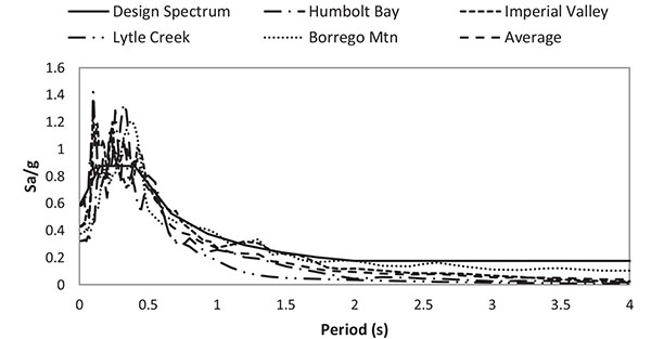
Nonlinear static pushover analyses were carried out according to [12] in order to evaluate the lateral capacity and the overall overstrength. In addition, nonlinear dynamic time-history analyses were performed to assess the seismic demand and the damage distribution. With this regard, a set of natural records was selected from PEER database [24] to be compatible with the EC8 having 10% probability of exceedence in 50 years, as shown in Fig. (5).
The basic data of the selected natural ground motions are listed in Table 3, which reports the magnitude (Mw), the mechanism, the closest horizontal distance to rupture plane (Rjb), the closest distance to rupture plane (Rrup), the time-averaged S-wave velocity in top 30 m (Vs30), and the characteristics of the site where acceleration was recorded.
| Earthquake Record | Year | Magnitude (Mw) | Mechanism | Rjb (km) | Rrup (km) | Vs30 (m/s) | Scale Factor |
|---|---|---|---|---|---|---|---|
| Humbolt Bay | 1937 | 5.8 | Strike-Slip | 71.3 | 71.6 | 219.3 | 8.8 |
| Imperial Valley | 1955 | 5.4 | Strike-Slip | 13.8 | 14.9 | 213.4 | 8.5 |
| Lytle Creek | 1970 | 5.3 | Reverse Oblique | 10.7 | 12.1 | 486 | 2.9 |
| Borrego Mtn | 1968 | 6.6 | Strike-Slip | 129.1 | 129.1 | 442.9 | 9.1 |
3. RESULTS AND DISCUSSION
Fig. (6a) shows the comparison of the capacity curves obtained varying the eccentricity e1 in terms of base shear coefficient (i.e. total base shear normalized to the total building weight) and roof displacement ratio (i.e. the roof drift normalized to the building height).
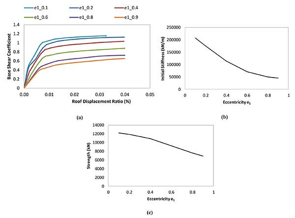
As it can be observed, decreasing the eccentricity e1 the seismic performance of the buildings improves in terms of initial stiffness and strength. This finding is more clearly described by plots depicted in Figs. (6b and 6c). For example, for e1= 0.1, the initial stiffness was 4.6 times larger than that with e1= 0.9 (namely 208173 kN/m in the former case and 44824 kN/m in the second case). Analogous results were obtained comparing the lateral strength of the buildings. Indeed, the lateral capacity of the gate braced building with e1 = 0.1 was 1.78 times that with e1 = 0.9.
The results from time history analyses are depicted from Figs. (7-11). In particular, Fig. (7) compares the maximum and average interstorey drift ratios varying the eccentricity e1. As it can be noted, the average interstorey drift ratio demand varied from 0.7% to 1.8%, thus showing the significant dependency on e1. The cases having eccentricity equal to 0.1 and 0.2 showed the better performance with the smaller interstorey drift ratio demand. As expected because of the increased deformability and the reduced strength, larger demand was recognized for larger values of the eccentricity.
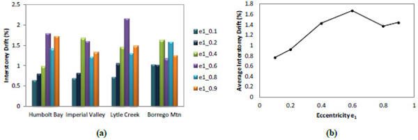
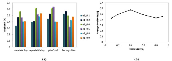
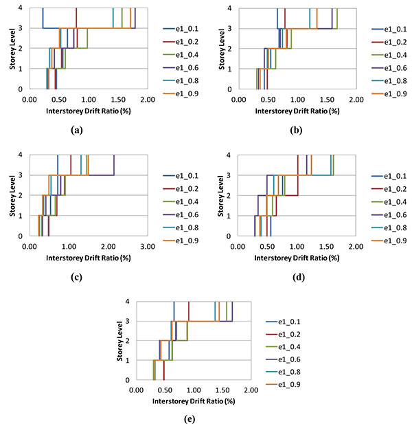
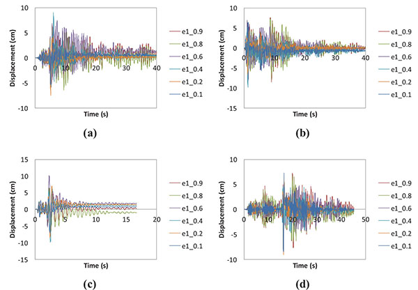
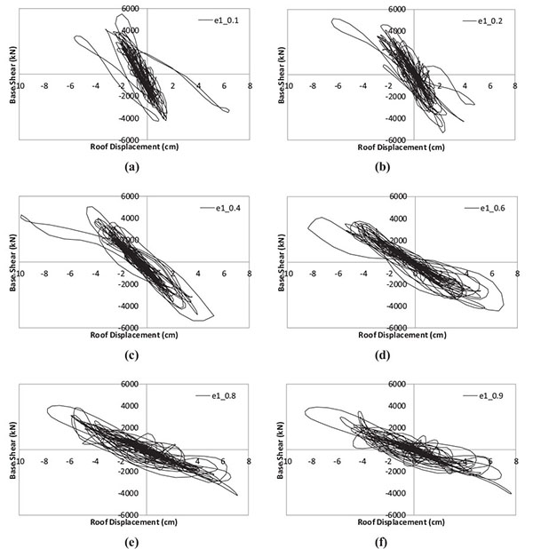
Fig. (8) shows the variation in terms of maximum roof drift under the set of utilized records (i.e. Humbolt Bay, Imperial Valley, Lytle Creek, and Borrego Mtn earthquakes) and also the distribution of the average peak roof drift. As it can be observed, for the Humbolt Bay earthquake, the case with e1= 0.4 experienced the maximum roof drift. However, under the Lytle Creek earthquake, the maximum roof drift was observed in the building having 0.6 eccentricity parameter. Therefore, being the variation of the roof drift demand dependent on both the characteristics of the earthquake and the eccentricity of the bracing system, it is not possible to draw up a general conclusion, which will require a wider number of cases to have statistic accuracy.
The distribution of the interstorey drift ratio demand along the building height varying the eccentricity and earthquakes is depicted in Fig. (9). Consistently with the results from pushover analysis, it was observed that gate braced frames with lower eccentricity had more uniform distribution than those having larger eccentricities under all earthquake ground motions. In addition, the effect of eccentricity on the storey drift ratio increases with the storey level. For example, as shown in Fig. (9a), for the case with e1 = 0.1 the storey drift ratio at the fourth storey level under Humbolt Bay earthquake is about 0.25% while that is about 1.80% for the e1= 0.9.
Fig. (10) shows the time history of the roof displacement of the gate braced frames with varying eccentricity under the four different seismic excitations (Humbolt Bay, Imperial Valley, Lytle Creek, and Borrego Mtn earthquakes). Generally, the reduction in the eccentricity from 0.9 to 0.1 remarkably decreased the value of roof displacement for all seismic excitations. For example, under the Imperial Valley earthquake, the maximum roof displacement of the structure with e1= 0.1 was about 64 mm while 85 mm for the case with e1= 0.9.
The effect of the eccentricity e1 on the hysteretic behaviour of the building under the Imperial Valley earthquake is illustrated in Fig. (11). As it can be recognized, the increment of e1 diminished the lateral strength and increased the displacement demand of the structure.
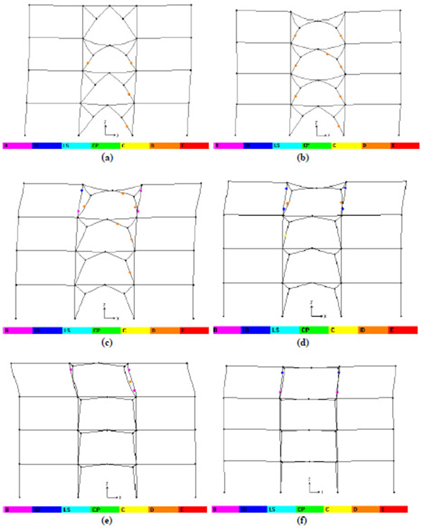
Fig. (12) shows the distribution of damage into the bracing members for all examined eccentricities under the Lytle Creek ground motion. The comparison of the hinge patterns confirms that the gate braced frames with smaller eccentricity are characterized by larger plastic engagement and more damage in the brace members. Moreover, it is worth noting that from e1 larger than 0.4 the examined frames were characterized by significant storey distortion that induced the formation of plastic hinges into the column belonging to the braced bay characterized by soft storey mechanism, even though the beam-to-column joints were assumed perfectly pinned.
CONCLUSION
This study investigated the influence of out-of-straightness eccentricity of bracings on the seismic response of gate braced frames that was assessed based on the nonlinear static and dynamic time-history analyses. The interpretation of numerical data inferred the following remarks:
- From the nonlinear static analysis, it was observed that the lateral stiffness and capacity of the structure increase by reducing the out-of-straightness eccentricity of bracings.
- The results based on the nonlinear dynamic analysis indicated that the eccentricity of gate bracing system had a significant role on the response of the building under the earthquake loads. It was observed that the peak interstorey drift ratios of the gate braced buildings varied from 0.7% to 2.2%, depending on the width of eccentricity.
- The gate bracing systems with lower eccentricity are characterized by a more uniform interstorey drift distribution than that with larger eccentricity.
- The use of lower eccentricity resulted in a significant reduction of the roof displacement up to about 25% in case of structures analyzed under the Imperial Valley earthquake.
- The comparison of the damage distribution revealed that the cases with lower eccentricity are characterized by greater plastic engagement in the brace members and less plastification in the other structural members.
CONFLICT OF INTEREST
The authors confirm that this article content has no conflict of interest.
ACKNOWLEDGEMENTS
Declared none.


