All published articles of this journal are available on ScienceDirect.

Dual-concentrically Braced Frames Using High Strength Steel – Seismic Response
Authors Info & Affiliations
Abstract
The recent technological advances on steel production process allowed introducing in construction market steel grades with significantly high yield strength. These new materials are known as High Strength Steel (HSS). The use of these steel grades offers economical and mechanical benefits compared with mild carbon steel (MCS). Consequently, their use is constantly increasing especially for seismic applications that are the rational field to exploit the high performance of HSS, by means of the “dual-steel” concept, which combines the HSS with MCS in order to provide overstrength to non-dissipative element and ductility to dissipative ones, thus controlling the global frame behaviour into a ductile overall failure mode. In this paper, a comprehensive parametric study devoted to investigate the seismic performance of Eurocode 8 compliant dual-steel chevron Dual-Concentrically Braced Frames (D-CBF) is presented and discussed. This structural typology is composed of two dissipative sub-systems acting in parallel, namely Moment Resisting Frames (MRFs) and Concentrically Braced Frames (CBFs). Static nonlinear pushover analyses were carried out in order to assess the seismic performance of the D-CBFs. The examined parameters cover both geometric and mechanical variables, as the type columns, span length, number of storeys and spectral shape. The analyses showed that the use of HSS in Eurocode 8 compliant D-CBFs is effective to avoid the damage in non-dissipative members. On the other hand, the use of HSS leads to design flexible members, especially for the braced-intercepted beams, resulting in poor performance of bracing members due to significant damage concentration. The economic evaluation shows that the use of HSS allows reducing the material consumptions and dropping the total constructional costs.
1. INTRODUCTION
The recent technological advances on steel production process allowed introducing in market steel grades with attractive properties like the increase of yield strength. For instance, the S355 steel grade was considered as high strength steel (HSS) until forty years ago. Nowadays, this steel grade is used frequently in civil application and a steel grade is considered as HSS when presenting yield strength equal or higher than 460MPa. The use of these steel grades offers economical and mechanical benefits compared with a mild carbon steel (MCS), and consequently, they are more frequently used in civil applications [1]. In fact, even though the steel market delivers larger prices for the HSS over MCS, the reduction of the material consumption due to higher yield strength may allow reducing the total costs of the construction.
In seismic application, the increase in steel strength may guarantee advantages especially when it is applied in non-dissipative structural members [2]. In current seismic codes, these members are designed to remain elastic during an earthquake and are responsible for the robustness of the structure and prevention of collapse, being characterised by high strength demands. On the other hand, specific zones should allow the development of plastic deformations (i.e. the dissipative elements). Therefore, the use of HSS seems to be an effective solution to provide adequate overstrength to non-dissipative members, while the dissipative zones are made with MCS providing ductility to structure. The structural systems made of two steel grades are termed as “Dual-Steel”. Recent studies [2-5] have highlighted their advantages for controlling the seismic response of multi-storey buildings by the achievement of overall ductile mechanism with noticeable reduction of constructional costs.
Accordingly, the study presented in this paper focuses on the assessment of seismic performance of dual-chevron concentrically braced frames (D-CBF) that are designed using the dual-steel concept.
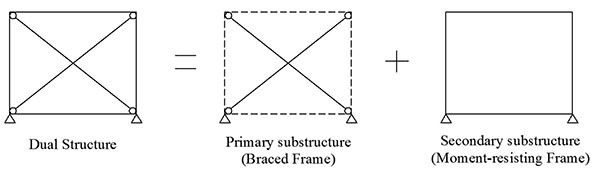
A Dual-Frame is a structural typology obtained by combining two structural sub-systems that work in parallel and contribute together to dissipate seismic energy dissipation induced by ground motion. In case of D-CBF, a sub-system is a concentrically braced frame (CBF), and the other is a moment-resisting frame (MRF). Iyama and Kuwamura [6] studied the probabilistic aspect of dual-system obtained by combining the CBF and MRF (Fig. 1) with different natural periods of vibrations. According to the authors, this structure may be called “fail-safe”, because it provides an alternative load path to earthquake loading (MRF) in case the primary system fails (CBF). The results showed that a dual-system provides a higher safety factor than structures made of a single seismic resisting system.
Therefore, the main objectives of this study are (i) to examine the seismic performance of HSS used in non-dissipative structural members for D-CBFs and (ii) assessment of economic efficiency. To these aims, within the framework of HSS-SERF research project [7] (i.e.. an European project aimed to investigate the seismic performance of dual-steel building frames), in this paper a wide parametric numerical study has been carried out. The study cases have been designed in accordance with Eurocodes [8-10]. Furthermore, the overall seismic performance has been analysed through static nonlinear analyses in the framework of EN1998-3 [11].
2. STUDY CASES
A set of twenty-four frames were defined. Therefore, the following design parameters have been analysed:
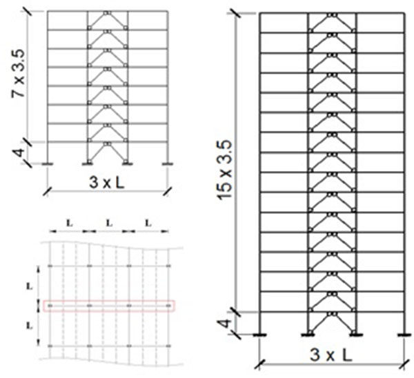
- Storey number: 8-storey and 16-storey frames, as shown in Fig. (2), where the height of first floor is 4.0 m and all other are 3.5 m
- Span length: 5.0 m and 7.5 m for 8-storey frames, because it is not realistic considering such a short span for taller buildings; 7.5 m for 8-storey and 16-storey frames
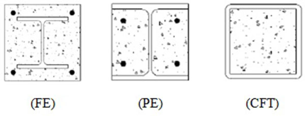
- Composite steel-concrete column typologies: steel-concrete column typologies (Fig. 3): fully encased (FE), partially encased (PE) and concrete filled tube (CFT)
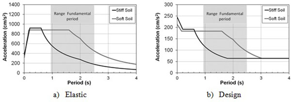
- Corner period of the design spectra: two types of soil conditions have been examined. The former representative of soil type C according to EN1998-1 [8] (hereinafter identified as “stiff soil”) and the latter representative of very soft soil conditions with corner period of 1.6 s, which are representative of specific soil condition in Bucharest (hereinafter identified as “soft soil”)
In order to identify each structure, the following label code has been given to the frames:
D-CBF_(Storey).(HSS).(Span).(Soil).(Column)
where:
- (Storey) = 1 for 8-stories and 2 for 16-stories;
- (HSS) = 1 for frames with S460 and 2 for the frames designed with S690;
- (Span) = 1 for 5.0 meters span and 2 for 7.5 meters span;
- (Soil) = 1 for stiff soil and 2 for soft soil;
- (Column) = 1 for fully encased columns, 2 for partially encased and 3 for concrete filled tube.
The analysed frames were extracted from an idealized reference building (Fig. 2), where braced alignments are alternated with those resisting only gravity loads. Therefore, the spacing of braced frames is equal to 2L, L being the span length in the transverse direction, as shown in Fig. (2). Floors are made of composite steel decks simply supported by steel beams (primary and secondary), which are restrained to avoid flexural-torsional buckling. Considering the low out-of-plane stiffness of gusset plate connections, braces are assumed as pinned on both ends. Owing to the high in-plane stiffness and the presence of flange stiffeners the beam-to-column joints of braced spans are assumed as rigid. On the other hand, the beams in the non-braced bays are assumed as pinned. Columns are assumed continuous through the building height. However, those belonging to the braced are considered fixed, while the remaining pinned at the base.
3. DESIGN ASSUMPTIONS
The study cases have been designed in accordance with EN1998-1 [8] and EN1993-1 [9], EN1994-1 [10]. In addition, some requirements provided by AISC 341 [12] have been also accounted for. In fact, in case of Dual Frames, AISC 341 [12] recommends to verify that MRF part should resist at least the 25% of the total lateral strength, thus participating in seismic resistance and energy dissipation capacity of the building. This additional requirement allows also sufficient redundancy to distribute the plastic engagement along the building height and preserving from the formation of weak storey mechanism, which typically characterize the response of simple braced frames. Although, this criterion is not covered by Eurocode 8 [8], it is not in contrast with EC8 requirements [8]. Moreover, all the detailing rules and capacity design requirements have been imposed according to EC8 [8].
In EN1998-1 [8], two limit states are defined in order to design both no-collapse and damage limitation performance levels. The former corresponds to seismic actions with a return period of 475 years. The aim is to guarantee that the structural integrity should be ensured for the safety of human life, although the structures may suffer severe damage. The damage limitation requirement is based on the deformability assuming the maximum interstorey drift ratio equal to 0.75%, which corresponds to adopting ductile non-structural elements.
In the design calculations, first order elastic modal response spectrum analyses were performed using finite elements commercial software Autodesk Robot (2010). According to EN1998-1 [8] (clause 4.3.3.3), the responses of all modes of vibration contributing significantly to the global response were taken into account. The combination of modal responses was made using Complete Quadratic Combination (CQC).
Dead and live loads were considered equal to 4.0 kN/m2 and 3.0 kN/m2, respectively. The peak ground acceleration was assumed equal to 0.32 g for both stiff and soft soil. The behaviour factor q was assumed equal to 4 αu/α1 = 4.8 according to the EC8 compliant “Ductility Class High” (DCH). The elastic and design spectra used on seismic design of the D-CBFs are given in Fig. (4), where the range of fundamental periods of the designed structures is highlighted by the grey vertical band.
Due to the high lateral stiffness of D-CBFs, the stability coefficients are smaller than 0.1, so that no amplification of design forces to account for P-Delta effects was necessary EN1998-1 [8]. However, the effects of initial sway imperfection have been taken into account by systems of equivalent horizontal forces as indicated by EN1998-1 [8].
3.1. Requirements for No-collapse State Limit
According to EN1998-1 [8], in case of the dual structural system both design rules and detailing requirements for MRF and CBF should be satisfied. Therefore, a set of requirements must be applied in MRF sub-system, where the beams are the dissipative members, and another for the CBF sub-system, where the braces are the dissipative elements.
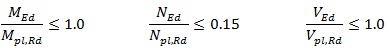
In EN1998-1 [8], the aim of the MRFs is to have beams where the full plastic moment resistance and rotation is not reduced due to compression and shear forces. Thus, the beams of the MRF subsystem should fulfil the following requirements:
 |
(1) |
In details, the moment applied (MEd) on beam should not exceed its design resistant moment (Mpl,Rd); the axial force (NEd) should not be higher than 15 percent of plastic resistance (Npl,Rd) and the capacity design establish that design shear (VEd) should not exceed 50 per cent of the design plastic shear resistance (Vpl,Rd). In addition, the shear force is obtained by the sum of shear forces due to the gravity and moment components on the beam (VEd = VEd,G + VEd,M).
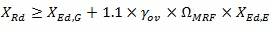
For the non-dissipative members (i.e.. columns), the resistance capacity should be verified by unfavourable combination of bending moments, axial or shear forces:
 |
(2) |
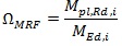
in which, X represents the any member force – axial (N), shear (V) or bending moment (M); the parameter ΩMRF corresponds to overstrength of the building. In Eq. 3, it is considered the minimum overstrength in the connected beams being defined as the overstrength of the most utilized beam:
 |
(3) |
The subscripts, “Ed,G” and “Ed,E”, correspond to seismic design situation for the gravity loads and lateral earthquake forces, respectively. In addition, the design axial forces on column base should not exceed 30% of resistance capacity.
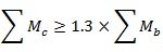
EN1998-1 [7] requires to satisfy at each beam-to-column joint the following local hierarchy criterion:
 |
(4) |
where Mc is the plastic bending strength of the column, while Mb is the plastic bending strength of the connected beams.
Regarding the CBF sub-system, the yield or compression resistance of diagonals (braces) should be higher than the design axial force (Npl,Rd or Nb,Rd > NEd). Furthermore, the non-dimensional slenderness plays an important role in the behaviour of concentrically braced. EN1998-1 [8] imposes an upper bound to non-dimensional slenderness equal to 2.0, while no lower bound is prescribed.
The non-dissipative elements (beams and columns) should be designed to resist the following condition:
 |
(5) |
Where Npl,Rd(MEd) is the design resistance of the beam or column taking into account the influence of the bending moment, NEd,G and NEd,E are the axial forces in non-dissipative element to seismic design situation for the gravity loads and lateral earthquake forces, respectively. The factor ΩCBF is the minimum overstrength corresponds to the following ratio from diagonal members:
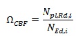 |
(6) |
In order to obtain a homogenous distribution of ductility, the EN1998-1 [8] mandates that the difference between the maximum and the minimum value of ΩCBF should lesser than 25%.
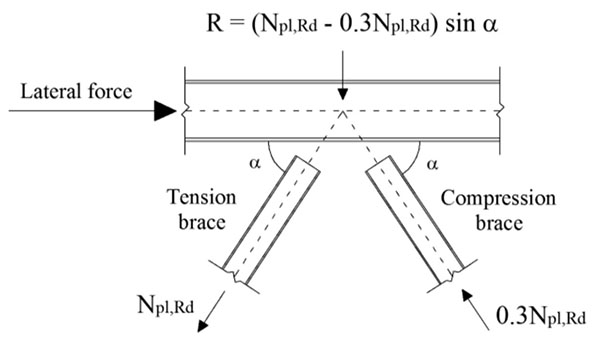
The brace-intercepted beams should be designed for gravity loading without considering the intermediate support due to presence of braces, as well as to resist an unbalanced vertical force occurring after the brace buckling. According to EN1998-1 [8], in this situation the brace under tension is assumed attaining its plastic strength, while the post-buckling resistance of the brace under compression is assumed as the 30% of its yield resistance. The distribution of forces to be considered on mid-length of the braced-intercepted beam is illustrated in Fig. (5)
As early discussed in Section 2.1, the examined building frames have been design considering an additional design requirement based on AISC 341 [12] on the minimum amount of lateral strength for the MRF part, which is expressed by the following:
 |
(7) |
where VRd,i is the base shear resistance at the i-th storey and αi is the angle that the braces make with the horizontal direction. Eq. (7) clearly shows that the minimum resistance of the MRF part is derived from the plastic resistance of the brace for a specify storey, which is evaluated assuming the plastic strength of the brace in tension and the post-buckling resistance of the brace in compression, the latter estimated according to EN1998-1 [8].
Finally, as it can be observed from Eqs. (3) and (6), two different Ω factors should be calculated, namely one for each structural system. Hence, the non-dissipative members belonging to MRF part should be designed applying the overstrength factor (ΩMRF) from the MRF part and the non-dissipative structural members from CBF system should be designed considering the brace overstrength (ΩCBF).
4. PUSHOVER NONLINEAR ANALYSIS
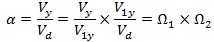
The pushover analyses were carried out according to EN1998-1 [8], applying two types of lateral load distribution: i) one proportional to the shape of first mode of vibration; ii) another proportional to the masses along the frame height. The overall overstrength factor α was calculated for all frames considering both load patterns, as follows:
 |
(8) |
where Vy is the base shear corresponding to the yield strength of the frame; Vd is the design base shear; V1y is the base shear corresponding to first plastic event that is the brace buckling in all examined cases. The first term, Vy/V1y, correspond to αu/α1 defined in the EN1998-1 [8]. This value depends on the frame configuration, formation of the collapse mechanism, redistribution capacity and gravity loading [13]. The second term (V1y/Vd) is related to aspects of the design procedure, such as member oversizing due to choices of commercial cross-section and a possible difference between actual and nominal material strength.
4.1. Modelling Assumptions
In order to assess the nonlinear behaviour of frames, static pushover analyses were carried out using the software SeismoStruct [14]. The models were developed using the force-based (FB) distributed inelasticity elements [15], thus allowing accounting for both material and geometric nonlinearities. The cross-section behaviour is reproduced by means of the fibre approach, assigning a uniaxial stress-strain relationship at each fibre.
The stress-strain relationship for concrete fibres in the column elements was determined using the model proposed by Martinez-Rueda and Elnashai [16]. Thereby, it was utilized the expressions proposed by Mander et al. [17] and Susantha et al. [18], for fully/partially encased and concrete filled tube, respectively.
In the case of steel members, the model proposed by Menegotto and Pinto [19] for the stress-strain curve was chosen.
The average values of both concrete compression strength and steel yield stress have been used. The former has been assumed according to EN 1992:1-1 [20]. Different values of material overstrength factor (γov) have been assumed for each steel grade as indicated by [21]. In particular, γov equal to 1.25 was assumed for S355, while 1.10 and 1.05 for S460 and S690, respectively.
Physical-theory models (PTM) were used to simulate the braces response, using the out-of-plane imperfection Δ0 calculated according to [22, 23]. As showed in recent studies [22-24] this approach is the most appropriate to simulate both the buckling and the hysteretic behaviour of bracing elements.
The numerical integration method used is based on the Gauss-Lobatto [25] distribution. Such feature allows each structural member to be modelled with a single FB element. In the present study, 5 Gauss-Lobatto integration points (IP) were used, while the cross-section of members was discretized using 200 fibres.
Second order effects were taken into accout through the crotational formulation given by [26].
Furthermore, the influence of P-Delta effects was modelled by applying a leaning column, where the seismic masses that are not tributary on frames were applied at each floor.
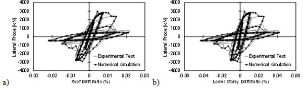
The accuracy of numerical models was validated against pseudo-static cyclic test results on a two-story full-scale chevron CBF [27]. Fig. (6) shows the comparison between numerical and experimental results in terms of base shear versus both roof and first storey drift ratios. As it can be observed, the simulated behaviour satisfactorily matches the test results, predicting buckling, post-buckling and fractures of braces.
4.2. Results
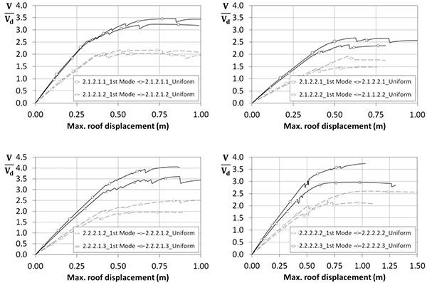
The capacity curves from pushover analyses for both 1st Mode and Uniform patterns are shown in Figs. (7) and (8), where the axis of ordinates corresponds to base shear normalized with the design base shear (hereinafter indicated as base shear ratio), while the roof displacements are reported in abscissas. It is interesting to underline that after the first nonlinear event (i.e.. the buckling of the braces) the frames present a sudden reduction in lateral resistance, and then, there is an increasing in their resistance and a deterioration of the overall stiffness. In particular, the eight-storey frames experience peak base shear ratios that range from 2.0 to 3.5 for the 1st Mode pattern, while a variation from 2.0 to 2.5 is observed for the taller frames. The uniform pattern gives peak base shear ratios ranging from 2.5 to 4.0 for both medium and high rise buildings.
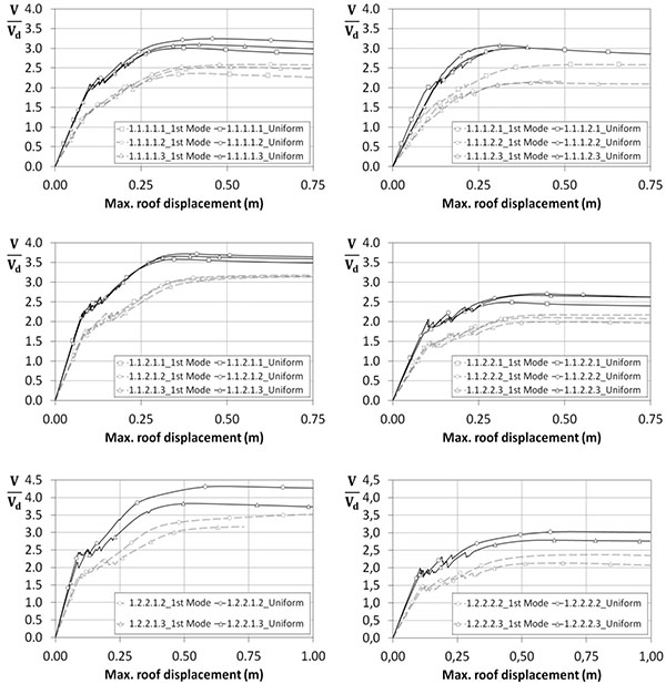
Focusing on the role of soil condition, the frames founded in soft soil condition experience the smaller base shear ratios. The difference between the base shear of the first plastic event and the maximum base shear is larger for frames designed for stiff soil condition. Indeed, the frames located in soft soil are designed considering a larger base shear due to their design spectrum with large corner period Tc, thus resulting in stronger and stiffer structures than those designed for stiff soil. In addition, the increase of the design base shear mitigates the influence of the slenderness brace criterion in the seismic design.
The comparison between the curves plotted in Figs. (7 and 8) allow highlighting the influence of the number of storey. The taller frames experience smaller base shear ratios compared to eight-storey frames, mainly for the first mode pattern. Indeed, under this load pattern sixteen-storey frames are generally characterized by soft storey mechanism which prevents plastic distribution and leads lower overstrength.
For what concerns the span length, the numerical results clearly show that this parameter has a negligible influence on the base shear ratios, which are almost the same for both examined values.
Furthermore, the frames designed with S690 show larger ratios compared to frames with S460, mainly for the taller frames. This issue can be explained considering the design overstrength factor and the good redistribution of the damage due to the improved redundancy provided by the increase of the steel grade. Since the frames with S690 have been designed for a larger overstrength factor they resulted in stronger structures than the frames with S460.
Regarding the influence of composite column typologies, there is no substantial difference among the three types of columns, especially for the eight-storey frames. However, the CFT columns are characterized by smaller base shear ratio than FE and PE columns. This result can be explained considering that the frames with CFT column have the smaller overall stiffness.
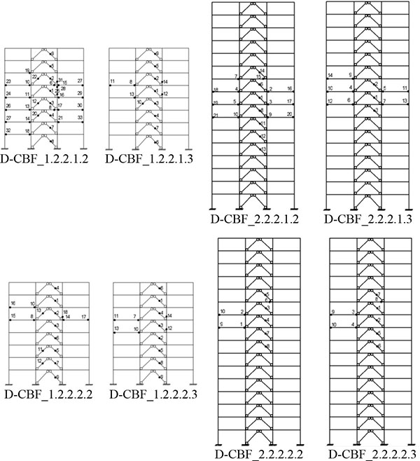
The damage distribution and its sequence are depicted in Figs. (9 and 10) for 8- and 16-storey frames, respectively, up to the attainment of an inter-storey drift ratio equal to 2% for the first mode load distribution. The brace buckling is always the first plastic event, which corresponds to sudden reduction of the lateral resistance into the capcity cuves. Afterwards, the “dual” effect is triggered and plastic hinges start forming at the beam ends of the MRF system. After that condition, some plastic hinges form into the brace-intercepted beams where the bracing member yields in tension.
It should be noted that plastic hinges in the MRF sub-system appear when the primary bracing sub-system has already experienced significant damage resulting in smaller overall lateral stiffness. These results confirm the effectiveness of dual-system concept, being the secondary sub-system able to withstands the earthquake forces after loss of lateral strength and stiffness is occurred in the primary sub-system [6].
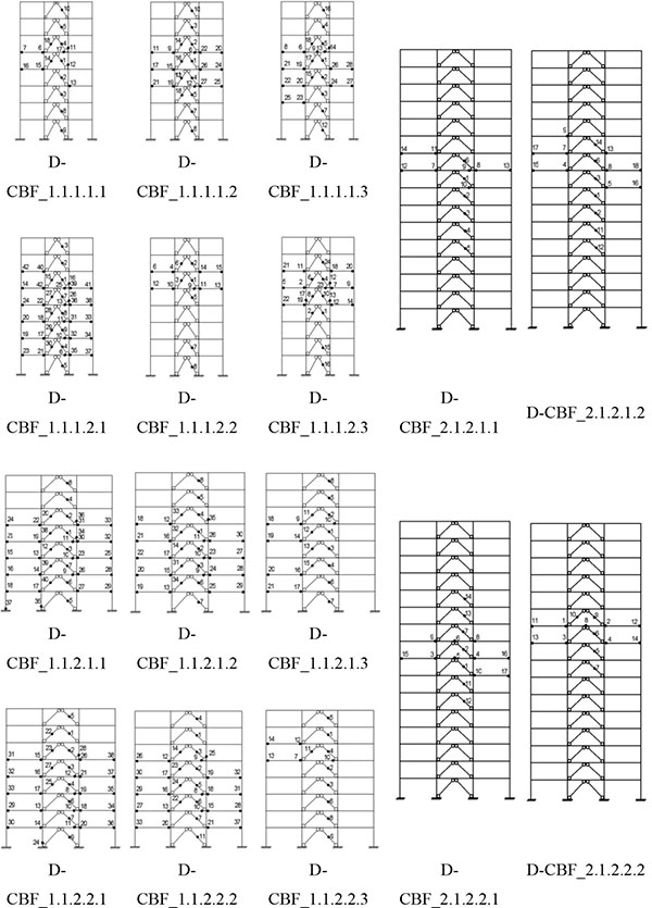
In addition, it is worth noting that increasing the steel grade for non-dissipative members lead reducing the number of plastic hinges in comparison with S460. However, increasing the steel strength does not mean increasing the sectional strength of members, but it implies enlarging the deformability. As a result, the relative stiffness of CBF is larger than MRF. Hence, the most of the lateral forces are sustained by braced cantilever, while MRF is less engaged. Concerning the braced frame sub-system, the use of S690 steel grade allows to meet easily capacity design criteria aimed at avoiding flexural yielding of the beams belonging to the braced bays. However, the possibility to use HSS for beams leads to very flexible and over-strong beams, resulting in increasing the axial compressive deformation of the braces and anticipating the braces fracture. Also recent research [28-32] points out that the seismic response of steel chevron concentric bracings is significantly influenced by the flexural behaviour of the beam belonging to the braced bay, being the vertical deflection of the brace-intercepted beam and the ductility demand of the brace in compression correlated phenomena.
The effectiveness of capacity design criteria is roughly confirmed being most of the plastic hinges concentrated on the dissipative structural members, except for some composite columns into mid-height of the buildings. Some beams from braced bays experience the formation of plastic hinges due to unbalance of vertical force resulting from the contemporary brace yielding in tension and post-buckling strength degradation in compression. Thereby, the post-buckling resistance considered in EN1998-1 [8] seems to be not conservative, thus confirming the results obtained by [28-32], which showed that brace-intercepted beams designed with the minimum required strength permitted by both current US and European design provisions could undergo significant vertical inelastic deformations which considerably increase ductility demands on both braces and beam-to-column connections. It should be noted that US design provisions for special CBFs mandate to design the beams for forces larger than European codes (e.g. post-buckling resistance in AISC341-10 [12] is equal to 30% of the buckling resistance, while that recommended by EN1998-1 [8] is equal to 30% of the tension resistance). Therefore, EN1998-1 [8] compliant D-CBFs are more affected by the beam flexibility than those designed according US codes.
In general, the D-CBFs show poor distribution of damage with large damage concentrations in the mid-height of the buildings, due to soft storey mechanism. In detail, the number of plastic hinges formed in the 16-storey frames is smaller in comparison with the 8-storey ones. Basically the MRF sub-system is not nearly triggered. In fact, the reason of this overall behaviour can be found in the EN1998-1 [8] design procedure, which aims controlling the mechanism by limiting the variation of brace overstrength in tension, disregarding the storey-to-storey variability of brace overstrength in compression. In addition, the sudden variation of column profiles implies a reduction of lateral stiffness. Indeed, as also demonstrated by [33] reducing the flexural stiffness of columns increases the story drift concentration. However, current Eurocode 8 [8] does not provide any requirements on minimum threshold for column flexural stiffness over the height of frames to limit damage concentration.
Regarding the overstrength factors, Table 1 reports the overstrength factors for the two lateral patterns used for the pushover analyses. As general remark, the uniform load pattern corresponds to the minimum overstrength factors associated to Ω1 factor, mainly for the 8-storey frames. The modal load pattern results in wide damage in the upper storey, even more severe in taller frames where a cantilever-behaviour is more pronounced. Moreover, under uniform load pattern the minimum value for the overstrength associated with design decision and the α factor has been recognized.
| Frames |  |
 |
 |
Load pattern |  |
Load pattern | Ω | Load pattern | ||
|---|---|---|---|---|---|---|---|---|---|---|
| 1st Mode | Uniform | 1st Mode | Uniform | |||||||
| D-CBF_1.1.1.1.1 | 1.74 | 1.60 | 1.36 | 1.87 | 1.60 | Uniform | 1.36 | 1st Mode | 2.37 | 1st Mode |
| D-CBF_1.1.1.1.2 | 1.90 | 1.57 | 1.36 | 2.07 | 1.57 | Uniform | 1.36 | 1st Mode | 2.59 | 1st Mode |
| D-CBF_1.1.1.1.3 | 1.82 | 1.62 | 1.39 | 1.92 | 1.62 | Uniform | 1.39 | 1st Mode | 2.52 | 1st Mode |
| D-CBF_1.1.1.2.1 | 1.44 | 1.38 | 1.47 | 2.34 | 1.38 | Uniform | 1.47 | 1st Mode | 2.11 | 1st Mode |
| D-CBF_1.1.1.2.2 | 1.48 | 1.52 | 1.45 | 1.52 | 1.48 | 1st Mode | 1.45 | 1st Mode | 2.15 | 1st Mode |
| D-CBF_1.1.1.2.3 | 1.37 | 1.36 | 1.55 | 2.32 | 1.36 | 1st Mode | 1.55 | 1st Mode | 2.12 | 1st Mode |
| D-CBF_1.1.2.1.1 | 1.89 | 1.64 | 1.66 | 2.18 | 1.64 | Uniform | 1.66 | 1st Mode | 3.14 | 1st Mode |
| D-CBF_1.1.2.1.2 | 1.88 | 1.68 | 1.70 | 2.22 | 1.68 | Uniform | 1.70 | 1st Mode | 3.18 | 1st Mode |
| D-CBF_1.1.2.1.3 | 1.90 | 1.62 | 1.65 | 2.25 | 1.62 | Uniform | 1.65 | 1st Mode | 3.14 | 1st Mode |
| D-CBF_1.1.2.2.1 | 1.51 | 1.25 | 1.40 | 1.99 | 1.25 | Uniform | 1.40 | 1st Mode | 2.11 | 1st Mode |
| D-CBF_1.1.2.2.2 | 1.57 | 1.33 | 1.39 | 2.03 | 1.33 | Uniform | 1.39 | 1st Mode | 2.17 | 1st Mode |
| D-CBF_1.1.2.2.3 | 1.45 | 1.57 | 1.38 | 1.70 | 1.45 | 1st Mode | 1.38 | 1st Mode | 2.00 | 1st Mode |
| D-CBF_1.2.2.1.2 | 2.01 | 1.78 | 1.75 | 2.43 | 1.78 | Uniform | 1.75 | 1st Mode | 3.52 | 1st Mode |
| D-CBF_1.2.2.1.3 | 1.75 | 1.77 | 1.81 | 2.16 | 1.75 | 1st Mode | 1.81 | 1st Mode | 3.16 | 1st Mode |
| D-CBF_1.2.2.2.2 | 1.67 | 1.53 | 1.42 | 1.98 | 1.53 | Uniform | 1.42 | 1st Mode | 2.37 | 1st Mode |
| D-CBF_1.2.2.2.3 | 1.51 | 1.44 | 1.40 | 1.93 | 1.44 | Uniform | 1.40 | 1st Mode | 2.13 | 1st Mode |
| D-CBF_2.1.2.1.1 | 1.07 | 1.28 | 1.94 | 2.61 | 1.07 | 1st Mode | 1.94 | 1st Mode | 2.08 | 1st Mode |
| D-CBF_2.1.2.1.2 | 1.13 | 1.50 | 1.93 | 2.38 | 1.13 | 1st Mode | 1.93 | 1st Mode | 2.18 | 1st Mode |
| D-CBF_2.1.2.2.1 | 1.07 | 1.24 | 1.41 | 2.12 | 1.07 | 1st Mode | 1.41 | 1st Mode | 1.51 | 1st Mode |
| D-CBF_2.1.2.2.2 | 1.03 | 1.15 | 1.86 | 2.22 | 1.03 | 1st Mode | 1.86 | 1st Mode | 1.92 | 1st Mode |
| D-CBF_2.2.2.1.2 | 1.24 | 1.22 | 2.02 | 2.65 | 1.22 | Uniform | 2.02 | 1st Mode | 2.50 | 1st Mode |
| D-CBF_2.2.2.2.3 | 1.20 | 1.29 | 1.63 | 3.29 | 1.20 | 1st Mode | 1.63 | 1st Mode | 1.96 | 1st Mode |
| D-CBF_2.2.2.2.2 | 1.10 | 1.13 | 1.90 | 2.37 | 1.10 | 1st Mode | 1.90 | 1st Mode | 2.09 | 1st Mode |
| D-CBF_2.2.2.2.3 | 1.28 | 1.29 | 1.63 | 1.94 | 1.64 | 1st Mode | 1.63 | 1st Mode | 2.09 | 1st Mode |
| 16th | 1.12 | 1.25 | 1.39 | 1.93 | 1.12 | 1.39 | 2.05 | |||
| 50th | 1.50 | 1.47 | 1.59 | 2.17 | 1.45 | 1.59 | 2.16 | |||
| 84th | 1.88 | 1.63 | 1.87 | 2.40 | 1.64 | 1.87 | 3.14 | |||
Analysing the influence of the number of storeys, the taller frames exhibit smaller Ω1 and α factors in comparison with eight-storey frames. This outcome is consistent with the plastic deformation and capacity curves evaluated in the previous section. The 16-storey frames have a wide damage concentration in the mid-height resulting in soft storey mechanism. On the other hand, the 8-storey frames provide larger overstrength factor, due to a better redistribution of damage along the building height. Regarding overstrength factors, Ω2, the 16-storey frames experience the larger values. For what concerns the overstrength related to design criteria, a median of 1.54 is observed for the 8-storey frames, while the taller frames present a value of 1.88 resulting in a decrease of 18%. Finally, a difference of 32% is found in the α factor with a median of 2.76 for the smaller frames and 2.08 for the other frames.
The length of span does not apprecciably influence the overstrength factors. In particular, frames with smaller span have medians of 1.52, 1.42 and 2.26, while other frames show values of 1.53, 1.52 and 2.65 for the Ω1, Ω2 and α factors, respectively.
Conversely, soil type affects the overstrensgth factors. The values reported in Table 1 indicate that the frames located in stiff soil condition present larger Ω1 and α factors. Indeed, the larger design base shear due to soft soil design spectrum reduces the influence of slenderness braces, especially on the last floor, on the seismic design. It results in structures with lower Ωdesign factors. All the frames designed for soft soil condition are stiffer and stronger than those designed for stiff soil, leading also to poor redistribution of damage after the first occurrence of brace buckling and soft storey mechanisms.
The frames located on stiff soil present values of 1.61, 1.68 and 2.55 for the Ω1, Ω2 and α factors, while values around 1.37, 1.43 and 2.11 are found for the frames located in soft soil. The largest difference is given for the α factor with a value of 21%.
The increase of the HSS steel grade provides structures with slightly higher overstrength factor, especially for the α factor. The values indicated in Table 1 show that the frames designed with S690 have an increasing of 7%, 6% and 11% for the Ω1, Ω2 and α factors, respectively. In fact, the buildings with this steel grade allow for a better distribution of the damage causing an increase of the lateral strength after the first plastic event.
Finally, the examined frames present a median value of the overstrength factor (as defined according to EN1998-1 [8]) equal to 1.45, which is larger than the adopted design value 1.2 that is recommended by EN1998-1 [8].
5. ECONOMIC EVALUATION
In this section, an economic evaluation is conducted to provide a comparison between the three steel grades (S355, S460 and S690) in terms of overall price of each frame. In general, there is a large set of factors that can affect directly or indirectly building costs, namely code provisions, site location, frame structure, construction time, capital costs, social and environmental factors, raw material costs, use of recycled materials, etc. Therefore, performing an economic evaluation is a complex task, since it depends on tangible and intangible factors that can decisively influence the final result. Nevertheless, since only a comparison between different solutions is aimed within this study, the procedure followed and described hereinafter can be considered sufficiently accurate to provide reliable conclusions. The indexes provided by STAHLBAU PICHLER SRL have been considered to determine the total cost of the frames taking into account the design, drawings, materials, and production costs. Regarding to concrete cost, the price provided by PREVETON CALCESTRUZZI SPA for a concrete C30/37 has been considered.
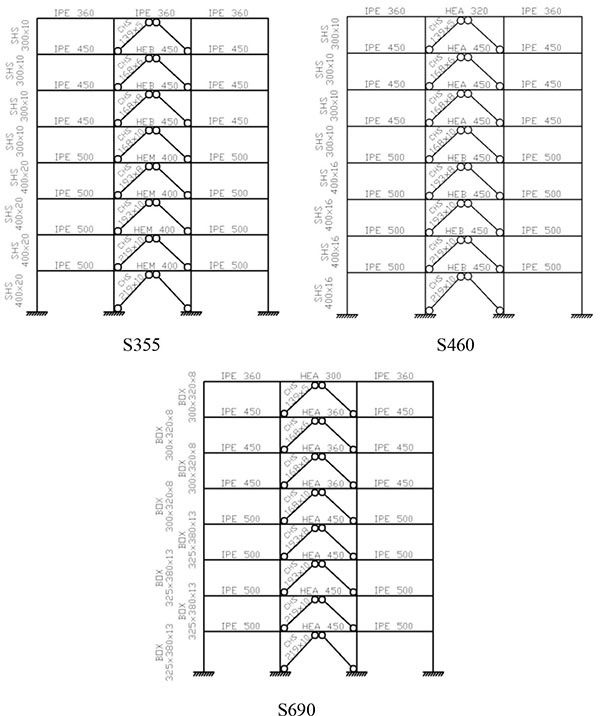
In order to perform the economic evaluation, a set of three frames have been selected using in non-dissipative structural member HSS with S460 and S690 to be compared with a conventional solution in which the frame is composed only for S355 steel grade for both dissipative and non-dissipative zones. The selected frames have been designed on the basis of the assumptions previously described in Section 2. In details, Fig. (11) depicts the selected members for both conventional and dual-steel structures. It is interesting to note that both MCS and dual-steel solutions lead selecting the same bracing frames. The most significant change can be found for columns that are smaller if dual-steel concept is adopted. Dual-steel frames are characterized by slightly larger periods of vibrations. Therefore, the overstrength factors from the seismic design are larger for frames with S690.
Table 2 reports the value considered for each item that can affect the frame costs. The indices used are applied to the total weight for different steel grades and concrete materials. The connections are considered by increasing 20% of the total steel weight. The average price for current S355 MRFs is estimated in 2150 €/ton taking into account the design, drawings, material, production, quality controls, transportation, installation and bolts. The prices presented in this table are based on the concept of prefabricated structural elements, i.e. beam and column elements are pre-assembled in the factory with dimensions allowing both easy transportation and erection on building site [7].
| ITEM | DESCRIPTION | ECONOMIC INDICES |
|---|---|---|
| DESIGN | Technical Office; Details “Engineerization”; Calculations Executive design; Design checks |
16 €/t |
| DRAWINGS | Static elements approval drawings | 60 €/t |
| MATERIALS | Steel (beams, columns and plates); Concrete | 1080 €/t |
| PRODUCTION | Pre-manufacturing within the factory | 450 €/t |
| QUALITY CONTROLS | Performed within the factory | 54 €/t |
| TRANSPORTATION | Supposed a range of transportation of 500 km; Means of transportations | 40 €/t |
| INSTALLATION | Necessary equipment; Laying; Need of high altitude works | 370 €/t |
| BOLTS | Supposed hot zinc-coated | 80 €/t |
| Frame reference | 2150 €/t | |
In Table 3, the weight of the frames examined for the D-CBFs is presented showing the contribution of each structural member. Once again, the connections have been considered at a flat rate as about the 20% of the total weight of the frame. In addition, the concrete consumption has been evaluated on basis of the dimensions of the column cross-sections.
| Frames | Weight | Total steel weight | Concrete | ||
|---|---|---|---|---|---|
| Columns | Beams | Braces | |||
| S355 | 19 | 22 | 3 | 53 | 42 |
| S460 | 16 | 19 | 3 | 46 | 44 |
| S690 | 12 | 19 | 3 | 41 | 40 |
Evaluating the results presented in these tables, there is a reduction of the weight of the frames when an HSS is used for the non-dissipative elements. Indeed, in the examined cases the seismic design was not governed by damage limitation and therefore the resistance plays an important role. The steel weight of frame designed with S460 is 10% lower than using S355, while it is 22% lower if S690 is used.
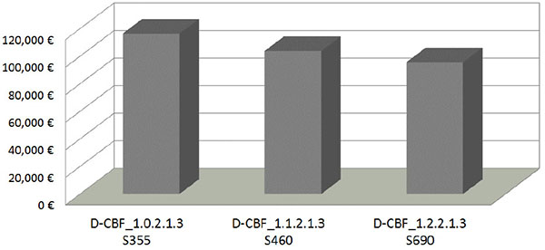
Fig. (12) shows the influence of steel grade on the price of the structures taking into account the values calculated above. The use of S460 gives a reduction of 12%, while for S690 the reduction is 21%. In fact, the use of the HSS on the non-dissipative structural members provides a considerable reduction of the total weight, which compensates the larger unitary cost of HSS thus reducing the final cost of the building.
CONCLUSION
A parametric study devoted to investigating the effectiveness of D-CBF using HSS in non-dissipative structural members is described in this paper. The frames have been designed according to EN1998-1 [8]. The examined design parameters are the type of column cross section, the span length, the soil condition, the frames height and the HSS grade for non-dissipative elements (namely girders and columns). Static nonlinear pushover analyses have been performed in order to assess the seismic performance. Based on the analysis of the results, the following conclusions can be drawn:
- The effectiveness of EC8 seismic design rules was confirmed by the plastic pattern with hinges developed into the beams of the MRF sub-system and non-linear behaviour of the braces of CBF part.
- The plastic hinges in the MRF subsystem appear when the primary bracing sub-system experiences significant damage with a substantial deterioration of lateral stiffness.
- The median overstrength ratio Ω1 was about 1.45. This value is larger than the value adopted in this study at design stage. Since EN1998-1 [8] does not recommend any value for the overstrength factor of the D-CBFs with chevron braces, this result can be a contribution for future discussion to revise the code;
- Regarding the overstrength ratio Ω2, associated to criteria of the seismic design, the median value is higher than 1.0 showing that the assumptions adopted in the seismic design stage does not provide structures with good level of optimization;
- In the opinion of the authors the inadequate behaviour of chevron CBFs is mainly due to the ineffectiveness of hierarchy requirements recommended by the current version of EN1998-1 [8], which do not guarantee adequate flexural stiffness to brace-intercepted beams in line with [28];
- From economic point of view it was observed that the use of HSS in non-dissipative structural elements represented an effective solution to limit the constructional costs.
CONFLICT OF INTEREST
The authors confirm that this article content has no conflict of interest.
ACKNOWLEDGEMENTS
The authors wish to thank the financial support granted by the Research Fund for Coal and Steel (RFCS) and all the partners involved in the research project HSS-SERF (High Strength Steel in Seismic Resistant Buildings Frames – Grant N0 RFSR-CT-2009-00024). The first Author wishes to thank the financial support from Erasmus Mundus External Cooperation Window – ISAC, the Brazilian PhD program – “Ciências Sem Fronteiras”.

