All published articles of this journal are available on ScienceDirect.
Finite Element Method of Composite Steel-Concrete Beams Considering Interface Slip and Uplift
Abstract
Introduction:
In order to analyze the displacement and internal force of composite steel-concrete beams under the vertical load, The finite element solution of composite steel-concrete beams under concentrated loads considering the existence of interface slip and vertical uplift based on the basic idea of elastic mechanics was derived in this paper.
Method:
A new kind of stiffness equation of bar system was got and its correctness was demonstrated with experimental value, the problem of composite beams considering the existence of interface slip and vertical uplift was solved, avoiding to produce large amount of calculation with the body element method.
Results and Conclusion:
It can be seamlessly integrated into the current engineering design software, which provides effective help to practical engineering problems.
1. INTRODUCTION
Composite steel-concrete beam is a new type of structure. Shear connectors between steel girder and concrete slab make them work together as a whole to resist interface slip and vertical uplift at the interface [1]. This structure is widely used in our country’s urban overpasses and building structure because of its characteristics of light weight, large stiffness, good plasticity, high strength, good stability, good integrality, long durability and short construction period. In China, Nie [2-4] in Tsinghua University studied the ultimate bearing capacity of composite steel-concrete beams, the ultimate bending capacity and strength expression of composite beams considering the effect of interface slip are derived on the basis of experiment.
Yu [5] has studied the interface slip and deformation of composite steel-concrete beams under vertical load, the formula of slippage is given. On that basis, Liu [6] has derived the analytical solutions of composite steel-concrete beams under vertical load, which can be used to obtain analytical expressions of stress and displacement in each part of composite beams just one time.
Lin [7, 8] has studied the behavior of composite steel-concrete beams under a negative bending moment. Load-displacement relationships, crack formation and its developing process, slip distribution at the interface of steel girder and concrete slab, and the flexural strain results of shear connectors were measured and studied. And she has built a three-dimensional FE model for numerical simulation analysis on horizontally curved steel-concrete composite beams subjected to negative bending moment. Hou [9] has made dynamic analysis of simply-supported steel-concrete composite beams under moving loads, obtained thegoverning motion equations considering the interface slip between steel girder and concrete slab. In other countries, Salari [10] has studied the slip effect of composite steel-concrete beams and pointed out that finite element analysis of composite beams based on force unit is accurate, it is economic and practical. Barnard [11] obtained many results based on test research of the flexural behavior of composite steel-concrete beams. The results are as follows: The existence of relative slip at the interface of steel girder and concrete slab is mainly due to the deformation of the shear connector under the action of horizontal shear.
The vertical uplift at the interface is mainly caused by different bending stiffness of steel girder and concrete slab. The above two conclusions effectively proved that the bearing capacity of composite beams calculated by transformed section method is greater than the actual bearing capacity of beam. Fabrizio [12] obtained a beam finite element for the long-term analysis of steel-concrete composite decks taking into account the shear lag in the slab and the partial shear interaction at the slab-girder interface.
Andrea [13] has studied the non-linear analysis of composite steel–concrete beams using the displacement formulation of the finite elements technique and illustrated some aspects related to the convergence of the method by comparing solutions deriving from finite elements with 8, 10 and 16DOF. Ranzi [14] has derived a stiffness formulation for the analysis of composite steel–concrete beams with partial shear interaction based on the direct stiffness method. The above studies will provide important references to the design and calculation of composite steel-concrete beams, but they are all only considering the effect of interface slip on mechanical behavior of composite steel-concrete beams without considering the effect of vertical uplift.
The existence of the lift force between steel girder and concrete slab will reduce combination effect and stiffness of composite beams, and it will increase the deflection thus affect its bearing capacity. Therefore, it is necessary to conduct in-depth researches on the effect of interface slip and vertical uplift to the mechanical performance of composite beams. Fu [15] calculated the uplift between steel girder and concrete slab in theory, compared the calculation results with the test results and gave analytic solution of composite beams considering the interface slip and vertical uplift at the same time. But the result is complex and tedious.
It is difficult to be mastered by actual technical personnel. Static and dynamic calculation theories of functionally graded beams/plates are derived in literature [16-20], which solve the problems of deflection, stress and dynamic response. They consider also the transverse shear deformation effect without requiring shear correction factors, have great significance in engineering. However, the contact effects of multi-layer structures are not addressed in these theories.
In summary, the existence of interface slip is commonly considered but the vertical uplift at the interface is seldom involved in most existing theories of composite beam. At the same time, the existing theoretical formulas are complex and hardly to promote, they are just for scientific research. The element stiffness equation of steel-concrete composite beams considering the slip and vertical uplift effect at the interface has not been discovered in the widely used finite element theories.
In this paper, the finite element solutions of composite beams considering interface slip and vertical uplift of steel girder and concrete slab under the vertical load is deduced based on elastic mechanics and contact theory. This method is not restricted by load and supporting conditions and it is convenient to be applied in practical engineering. A simple and quick calculation theory to the engineering design problem of composite steel-concrete beams is provided.
2. BASIC ASSUMPTIONS
According to the actual deformation and loading status of composite steel-concrete beams, the basic assumptions are as follows: (1)Steel girder and concrete slab conform to plane cross- section assumption, respectively; (2)There is vertical displacement difference between steel girder and concrete slab; (3)There is horizontal slip at the interface of steel girder and concrete slab; (4)The horizontal shear stress and the vertical stress transferred at the interface are proportional to the relative displacement difference between the lower edge of concrete slab and upper edge of steel girder.
3. DERIVATION OF THE ELEMENT STIFFNESS MATRIX
3.1. Selection of the Displacement Mode
From Fig. (1), in order to obtain the element deformation model for the composite steel-concrete beams, it is needed to determine the nodal degrees of freedom of the element according to the actual deformation characteristics of composite beams. According to assumptions (2) and (3), there are different vertical displacements, horizontal displacements and different angles between two beam elements. Therefore, the independent degrees of freedom on each node of composite beam element will be six, i.e. the axial displacements of the concrete slab and the steel beam uc and us ; the vertical displacements of the concrete slab and the steel beam vc and vs ; the angles of rotation at concrete slab and the steel beam θc and θs . Thus, the node displacement vector of the composite beam is Eq.(1).

 |
(1) |
where the subscript ‘1’ and ‘2’ represent the left and the right node, respectively.
When the number of nodal degrees of freedom is determined, the displacement mode of the element can be set down. The axial displacement and the vertical displacement use quadratic function and quartic function, respectively, are Eqs.(2) ~ (4).
 |
(2) |
 |
(3) |
 |
(4) |
where x is axial coordinates of elements,c1~c5, c10~c12 are undetermined coefficients.
The internal forces can be obtained according to the relationships between the internal forces and displacements [3] as Eqs.(5) ~ (9).
 |
(5) |
 |
(6) |
 |
(7) |
 |
(8) |
 |
(9) |
where Nc is axial force of concrete slab, Mc is the bending moment undertaken by concrete slab, Qc is the shear force undertaken by concrete slab, qvc is the vertical uplift force at interface,quc is the horizontal shear force at interface, Ec is elastic modulus of concrete, Ic is inertia moment of concrete slab,’ means partial derivative of x,(n)means n order partial derivative of x.
Set
 |
(10) |
 |
(11) |
Integrating Eqs.(10) and (11) yields Eqs.(12) ~ (17).
 |
(12) |
 |
(13) |
and
 |
(14) |
 |
(15) |
 |
(16) |
 |
(17) |
According to the relationships between the internal forces and the displacements as Eqs.(18) ~ (22).
 |
(18) |
 |
(19) |
 |
(20) |
 |
(21) |
 |
(22) |
where Ns is the axial force of steel beam, Ms is the bending moment undertaken by steel beam, Qs is the shear force undertaken by steel beam, qvs is the vertical uplift force at interface,qus is the horizontal shear force at interface, Es is the elastic modulus of steel, Ic is the inertia moment of steel beam.
The vertical stresses at the interface are equal, i.e. Eq.(23).
 |
(23) |
Substituting Eqs. (8),(21) and Eqs. (9),(22) into Eq.(23) obtains Eq.(24).
 |
(24) |
After substituting α and β into Eqs.(13) and (17) we will get the following formulas as Eqs.(25) ~ (27).
 |
(25) |
 |
(26) |
 |
(27) |
3.2. The Displacement Relationship of the Composite Beams
The horizontal displacement at the cross section of the composite beam is depicted in (Fig. 2).
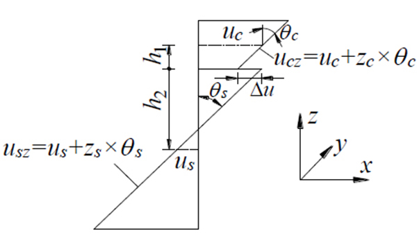
From Fig. (2), the expression of the horizontal displacement difference can be obtained as Eq.(28).
 |
(28) |
where h1 is the distance from the section centroid of the concrete slab to the interface, h2 is the distance from the section centroid of the steel girder to the interface. The vertical displacement difference is Eq.(29).
 |
(29) |
The relationship between the displacement difference and the stress of interface is Eq.(30).
 |
(30) |
where qv and qu are the vertical stiffness and horizontal stiffness of the connecting bolt, respectively, k1 and k2 are the vertical stiffness and horizontal stiffness of the connecting bolt, respectively, l is the space of the bolts.
The vertical stiffness of bolt can be calculated by the method in Ref [15] as Eq.(31):
 |
(31) |
Where Est is the Young’s modulus of the bolt, Ast is the cross sectional area of the bolt, lst is the length of the bolt.
The shear stiffness of bolt can be calculated by the method in Ref [6] as Eq.(32) , (33).
 |
(32) |
 |
(33) |
fck is the prismatic compressive strength of concrete, As is the cross section area of bolt, Ec is the Young’s modulus of concrete, ns is the column number of bolts.
Substituting Eqs. (28), (29) into (30) and setting l = 1 arrives at Eqs.(34) and (35).
 |
(34) |
 |
(35) |
3.3. Determination of the Element Displacement Matrix
The 12 boundary conditions of the constraint element are shown in Eq.(36).
,
 |
(36) |
Simultaneous (34),(35) and (6),(19) respectively, then substitute midpoints into them as Eqs.(37) and (38):
 |
(37) |
 |
(38) |
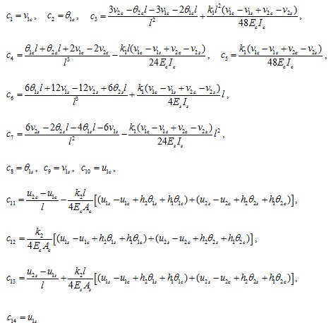
Substituting Eqs.(27)~(32) into Eq.(36), and combining with Eqs.(37) and (38), one can solved the coefficients as Eq.(39).
 |
(39) |
Take (39) back into the trial function and show with the form of matrix as Eq.(40):
 |
(40) |
3.4. Elemental Generalized Strain Matrix and Generalized Force Matrix
By the basic principles of elastic mechanics as Eq.(41).
 |
(41) |
Where kv (x) εu (x) is the horizontal strain. Taking the derivatives of Eq.(40) yields Eq.(42).
 |
(42) |
Equation (42) can be denoted as Eq.(43).
 |
(43) |
where B is the generalized strain matrix.
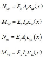
By the physical equations of the beam as Eq.(44):
 |
(44) |
where Ec and Es are the Yong’s modulus of concrete slab and steel girder, respectively; Ic and Is are second moment of area of concrete slab and steel girder, respectively.
Substituting Eq. (42) into Eq. (44) yields Eq.(45).
 |
(45) |
Equation (45) can be denoted as Eq.(46).
 |
(46) |
where N is the generalized force matrix.
3.5. The Expression of Element Stiffness Matrix
Set the nodal force vector of the element as Eq.(47).
 |
(47) |
The total potential energy of element is Eq.(48).
 |
(48) |
According to the principle of minimum potential energy, make the first variation of the potential energy function of the system equal to zero AS Eq.(49).
 |
(49) |
From Eq.(49), the static equation of the beam can be obtained as Eq.(50).
 |
(50) |
where
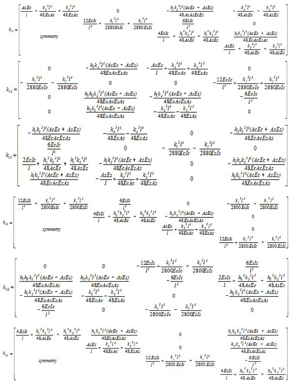
 is the element stiffness matrix, which can be expressed explicitly as Eq.(51) and (52).
 |
(51) |
where
 |
(52) |
4. SOLUTION OF THE NODE DISPLACEMENT MATRIX
The global stiffness equation of structure can be obtained from literature [21-23] as Eq.(53).
 |
(53) |
where K is the global stiffness matrix, P is the original equivalent load vector, δ is the nodal displacement vector.
The global stiffness matrix K and the original equivalent load matrix P can be obtained by assembling the element stiffness matrix Ke and the equivalent load matrix Pe that already obtained as Eqs.(54) and (55). When the load is uniformly distributed load q
 |
(54) |
when the load is concentrated load p
 |
(55) |
The node displacement matrix δ can be obtained by substituting them processed by multiplied with bigger number method into Eq.(53).
5. EXAMPLE OF VERIFICATION AND ANALYSIS
In order to demonstrate the correctness of the presented method for calculating the slippage and uplift of composite steel-concrete beams, two composite beams with their sectional dimensions shown in Fig. (1) were tested and calculated. The span of this composite beams is 4.0m and the size of concrete slab is 800mm × 80mm, the size of steel roof is 120mm × 6mm, the size of the steel web is 6mm × 238mm, the size of the steel bottom slab is 120mm × 6mm.The diameter of bolt is 12mm and the arrangement form of bolts is double row and symmetrical, the spacing of each row is 60mm,along the beam length direction bolts was uniform arranged and the spacing was 200mm of each row. Concrete grade of roof is C40 and the steel grade of steel girder is Q335, the performance level of bolt is 6.5. 50kN concentrated loads were applied at 1.4m from the beam at both ends. The model has 40 units. The calculation time is 3minutes.
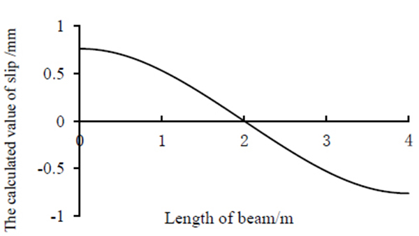
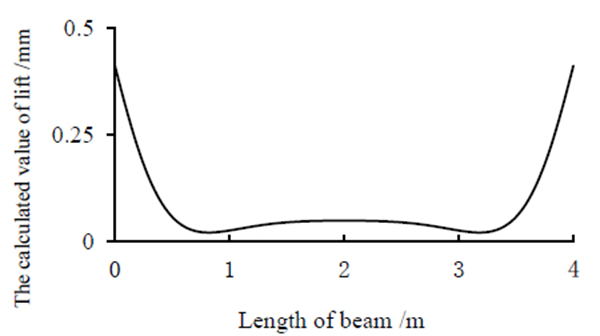
The comparisons of the results calculated by the presented method and the experimental results are shown in (Figs. 3-6).
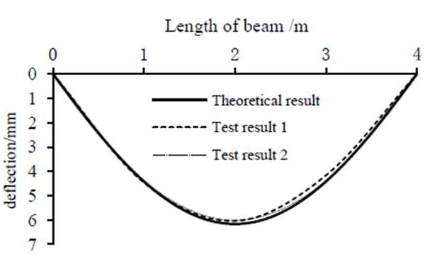
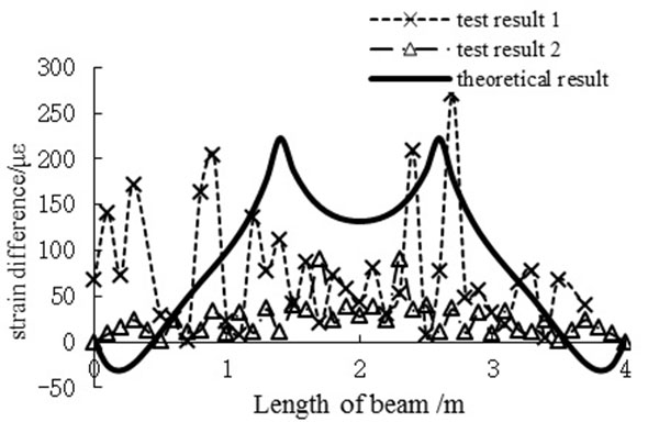
By comparison, the results of calculation got by the method of the new type of bar system finite element and testing are in good agreement. Both deflection and slip strain difference are shown in Figs. (3 and 4). As shown in Fig. (3), the values of midspan deflection obtained from test 1 and test 2 are 6.07mm, and the calculated value is 6.20mm. The relative error between the results of calculation and testing is 2% at most. Fig. (4) shows that slip strain difference presents M-shape along the beam, and the curve is symmetrical. It should be noted, there are some discrepancies between the results of calculation and testing of slip strain difference, the possible reasons may be the existence of test errors, which mainly from the positions of studs and the sticking positions of strain gauges. It can be proved that element stiffness matrix derived in this article is correct. At the same time calculated results of relative slippage and the value of vertical lift can be obtained quickly and accurately by using the calculation method, perfecting the calculation theory of composite beams that only considering slip effect. According to the results shown in Figs. (5-6), the uplift has almost the same order of magnitude of shear slip near the beam ends, however in the central region of the beam, it is almost zero. It shows that uplift is relevant and can't be ignored, especially when flexible shear connectors are provided between steel girder and concrete slab. Due to the deformation of flexible shear connectors, it can only play a part of the horizontal shear and vertical uplift effect. And it must be said that the element is not able to take into account the shear-lag effect, which can be necessary to evaluate the effective width. The method can be obtained from Ref [24].
CONCLUSION
- The finite element solution of composite steel-concrete beams considering the existence of interface slip and vertical uplift is derived for the first time based on elastic mechanics and contact theory which solves the problem of slip and uplift at the interface of composite beams using common finite element method.
- Comparing the results of calculation and test result of composite steel-concrete beams, the correctness of the finite element of composite beams derived in this paper was assessed.
- The finite element method is feasible and effective. The element stiffness matrix was derived in this paper. It can be seamlessly integrated into the current engineering design software and provide effective help to practical engineering problems. It can not only be used to calculate the displacement and stress of steel-concrete composite beams under vertical loads, but also can calculate inner force and distortion of bridge deck pavement casted by stages under the vehicle loads. It provides an accurate calculation method for the large span beam-type structure with steel-concrete composite beams.
CONFLICT OF INTEREST
The author confirms that this article content has no conflict of interest.
ACKNOWLEDGEMENTS
Declared none.


