All published articles of this journal are available on ScienceDirect.

Bending Characteristics of a Post-Tensioned, Prestressed Concrete, Simply Supported Beam
Authors Info & Affiliations
Abstract
Introduction:
To analyze the basic, mechanical properties of post-tensioned, prestressed concrete, simply supported beams with grouting material of varied porosity under load, a finite element model is established by using ANSYS finite element software.
Methods:
The mid-span, cracking deflection and the equivalent stress of the prestressed, concrete beams with grouting material of varied porosity are calculated under different load forms.
Results and Conclusion:
The analysis results show that the cracking deflection of the prestressed, concrete beams increases with the increase in the porosity of the grouting material of the beams under different load forms. By contrast, under the same porosity grouting material, the cracking deflection of the symmetrical loads is larger than that of the uniform and concentrated loads. As the porosity of the grouting material increases, the peak value of equivalent stress decreases. The equivalent, stress-peak value of the concentrated load is always larger than the equivalent, stress-peak value under the uniform and symmetrical loads.
1. INTRODUCTION
Due to national economic development and construction, low steel production, large demand, and tight supply, prestressed concrete structures have been utilized extensively in the field of civil engineering from the middle of the last century. After decades of research and engineering practice, prestressed concrete technology has matured. Prestressed concrete structures have many advantages. Prestressed concrete structures exhibit reduced cracking, increased seismic ductility, and optimized building functionality. At home and abroad, prestressed concrete structures are widely used in the field of civil engineering [1-3].
Since its development, many scholars at home and abroad have studied prestressed concrete. Padmarajaiah et al. [4] studied the cracking width of post-tensioned, prestressed, high-strength concrete beams. Nawy et al. [5] performed bending tests on 22, post-tensioned, unbounded, prestressed, high-strength, reinforced concrete beams. Huang et al. [6] conducted an experimental study on the prestressed, high-strength, lightweight, aggregate concrete, continuous, rigid-frame bridge. The flexural performance of a post-tensioned, bonded, prestressed, reinforced, concrete beam with 500 MPa steel bars was studied by Du [7] Kara et al. [8] studied the effect of load types and prestressing force on the effective moment of inertia and deflection of the beam by finite element analysis. Dong et al. [9] derived the deflection
formula of prestressed concrete beam through experimental study and theoretical analysis. However, this complex formula is not practical for application since it has a wide margin for error in calculation. The three-dimensional, finite element model of the bridge was established by Zhou et al. [10] by using ABAQUS software. The effect of prestressed steel bars on concrete was simulated by the temperature drop method. The numerical simulation of the bridge was carried out under a static load to test the effectiveness bridge prestressing analysis by the temperature drop method. Huang [11] primarily studied the finite element-modeling method of the post-tensioned, prestressed concrete structure. The challenge of post-tensioned, prestressed concrete structure modeling is dealing with the interface between the concrete and prestressed tendons. Cao et al. [12] conducted two, static tests of post-tensioned, bonded, prestressed concrete beams in two stages of fatigue tests and analyzed the change in the nonlinear, dynamic characteristics of the beam's damage. Jia et al. [13] introduced the results of the bending test in the four-part, prestressed, ultra-high strength concrete beam to evaluate the effect of the prestressed, tendon depth and area on the bending behavior of the beam Liu et al. [14] developed a new three-segment beam model with local flexibilities at crack tips to investigate the vibration of a cantilever beam with a closed.
The study of the prestressed concrete, simply supported beam is well represented in the civil engineering field. Its performance can be comprehensively analyzed by theoretical calculation, experimental result, and finite element simulation. The finite element method is widely used in the construction industry and is applied to high-rise buildings, bridge design, roadbed paving, and slope engineering. The finite element analysis method will eventually replace the traditional experimental analysis method. ANSYS finite element software is currently used to study the relationship between the stress and strain of the prestressed concrete, simply supported beam under uniform load; the damage of the concrete by stress and strain; and the relationship between the load and displacement. It is primarily used for the finite element analysis of nonlinear structures in prestressed concrete.
The prestressed concrete, simply supported beam is one of the most widely used structures in reinforced concrete. Some scholars have conducted extensive research on prestressed concrete, simply supported beams. At home and abroad, the reinforced concrete structure has become an indispensable part of modern architecture. Currently, there are many studies on the mechanical properties of prestressed concrete, simply supported beams. The primary effects of varying types of reinforcement and concrete on the flexural failure of the prestressed concrete beam have been studied. Numerous conclusions have been drawn regarding the bearing capacity of prestressed concrete, simply supported beams. However, there are few studies involving the laws governing the cracking and equivalent stress of the post-tensioned, prestressed concrete, simply supported beam with grouting materials of varied porosity.
In summary, as established by a comparative analysis of numerical simulations, this paper examines the model of the post-tensioned, prestressed concrete simply supported beam under different load forms. The laws regarding the cracking, deflection, and equivalent stress of the prestressed concrete beams with grouting materials of four different porosities (reserved void without grouting material, reserved void for filling 1/3 grouting material, reserved void for filling 2/3 grouting material, and full void) serve as a point of reference for the application of the prestressed beam.
2. MATERIAL CONSTITUTIVE RELATION
2.1. Concrete Constitutive Relation
The stress-strain relationship of concrete serves as the basis for calculating the strength of the reinforced concrete members, the internal force analysis of statically indeterminate structures, and the calculation of the structural ductility and finite element analysis of reinforced concrete. For decades, many scholars have devoted themselves to studying the nonlinear properties of the concrete compressive stress-strain relationship and exploring the reasonable, mathematical expression between stress and strain [14].
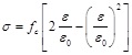
The stress-strain curve of concrete used in China for engineering application is the Hongnestad model [16]. The rising section of the model is the quadratic parabola and the descending section is the oblique line:
Ascending segment:
 |
Descending segment:
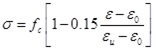 |
where fc is peak stress (the prism compressive strength); ε 0 is strain corresponding to peak stress, valued as ε 0 = 0.002; and εu is ultimate compressive strain, valued as εu.
2.2. Steel Bars Constitutive Relation
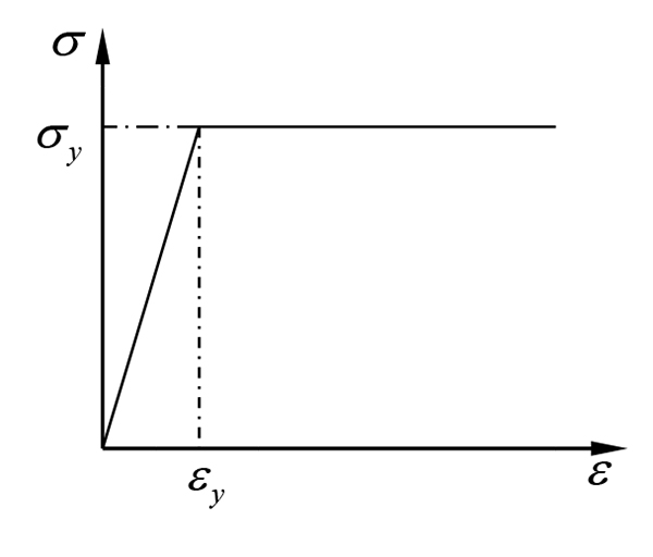
In this paper, the bilinear hardening model is adopted for prestressed and non-prestressed reinforcement [15]. The stress-strain relationship of ideal, elastic-plastic is used for non-prestressed reinforcement. As shown in Fig. (1):
when,
 |
when,
 |
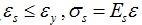
where εs, σs, E s are the strain, stress and elastic modulus of non prestressed reinforcement; and ε y, σy, fy are the strain, stress, and yield stress of common steel bars.
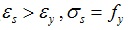
The stress-strain relationship of prestressed reinforcement is shown in Fig. (2), it is assumed that the steel bar is pulled off when the stress reaches ultimate strength. Among them, εu, and σu are the ultimate strain and ultimate tensile stress of prestressed reinforcement. εy is the yield strain of prestressed reinforcement, and 0.75σu is the yield stress of prestressed reinforcement:
3. FINITE ELEMENT MODELING OF POST-TENSIONING PRESTRESSED CONCRETE BEAM
3.1. Calculation Parameters
When using ANSYS finite element software to calculate and analyze the structure, the concrete parameters of post tensioned, prestressed concrete beam are obtained according to the material performance test: the uniaxial compressive strength is 40.3 MPa; the uniaxial tensile strength is 1.43 MPa; the elastic modulus is 3×10⁴ MPa; Poisson’s ratio is 0.2; and the per unit volume gravity of reinforced concrete is 25 kN/m3. The uniaxial stress-strain of concrete is calculated according to the formula of the concrete structure design code. The longitudinal tensile main bar is made of a hot-rolled, round, steel bar with a diameter of 10 mm and a yield strength of 300 MP. According to the requirements of the structure, the upper part of the beam is provided with 2, hot-rolled, round, steel bars with a diameter of 10 mm and a yield strength of 300 MPa. The stirrup adopts the hot-rolled, round, steel bar with a diameter of 6 mm and spacing of 100 mm and yield strength of 300 MPa. The prestressed steel wire with a diameter of 6 mm (1×7-6) and tensile strength of 1270 MPa adapts the linear layout, and the spacing, from the outer wall of the reserved void using metal bellows to the bottom of the beam, is 40 mm. To calculate the model, the section of prestressed concrete beams is 150 mm×250 mm, the span is 2100 mm, and the clear span is 1800 mm . The load is divided into three types: concentrated loading, symmetrical loading, and uniform loading. The post-tensioned, prestressed concrete beams are divided into four cases: the reserved void without grouting material, the reserved void for filling 1/3 grouting material, the reserved void for filling 2/3 grouting material, and the full void. The parameters selection of the prestressed tendon and the pipe combines with the material of the corrugated pipe. The friction coefficient, μ=0.3158, the pipeline deviation coefficient, k=0.0015, and the material parameters are shown in Table 1.
| Material | Specifications | Unit | Elastic modulus (MPa) |
Poisson ratio |
|---|---|---|---|---|
| Concrete | 30 MPa | Solid65 | 3×10⁴ | 0.2 |
| Common reinforcement | 10 mm | Link180 | 2×10⁵ | 0.25 |
| 6 mm | Link180 | 2×10⁵ | 0.25 | |
| Prestressed reinforcement | 6 mm (1×7-6) | Link180 | 1.95×10⁵ | 0.3 |
3.2. The Model Establishment
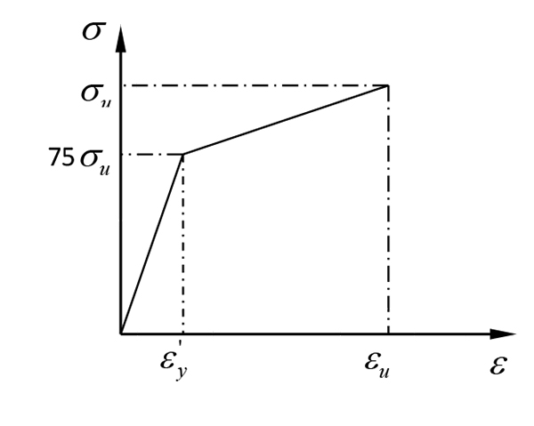
The finite element model of post-tensioned, prestressed concrete beams is shown in Fig. 3 and is composed of concentrated, symmetrical, and uniform loading. The finite element model adopts a separate model and includes the concrete unit; the common reinforcement unit; the prestressed, reinforcement unit; and the adopt Solid65 unit. The Solid65 unit is used to simulate the concrete, rock, and other compressive capacity, which is much greater than the tensile capacity of the heterogeneous material. The Solid65 unit is based on a conventional, 8 node, three-dimensional, isoparametric element and is added to the concrete material parameters and integral reinforcement model. The prestressed and common bars are a slender material that can typically be neglected in transverse, shear strength. Thus, the prestressed and common bars can adapt unit Link180. This is called the 3D finite strain rod unit and consists of two nodes with each node having 3 degrees of freedom. The translational displacements run along the X, Y, and Z directions of the joint and can withstand axial tension but cannot bear bending moment. The bond between the prestressed steel wire and concrete is simulated by the Combin14 unit; the bond coupling of prestressed, steel wire; and the concrete in three directions. The bonding effect between prestressed steel wire and concrete can be simulated by adjusting the elastic coefficient of the Combin14 unit. The influence of the grouting quality on the beam can then be obtained.
For the finite element mesh division, the length of the beam is divided into 42 sections. Each section length is 50 mm. The cross section is divided into 60 squares with a length of 25 mm. The concrete beam is divided into 2520 units. The boundary condition of the prestressed concrete, model beam is simply supported at both ends. In the calculation of the finite element model, the self-weight, prestress, and load applied to the upper part of the beam are considered:
4. THE CALCULATION RESULTS ANALYSIS
4.1. Deflection Analysis
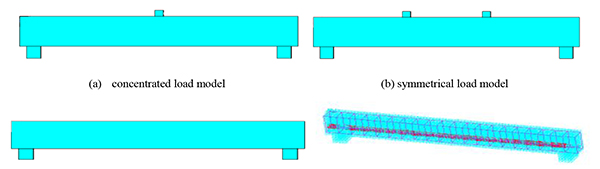
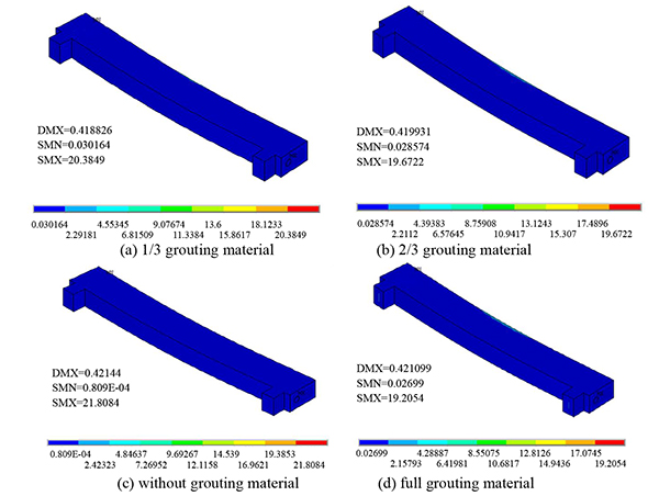
Under concentrated, symmetrical, and uniform loads, the cracking deflection nephogram of the post-tensioned, prestressed concrete beams is shown under the four conditions (the reserved void without grouting material, the reserved void for filling 1/3 grouting material, the reserved void for filling 2/3 grouting material, and the full void) in Figs. (4-6).
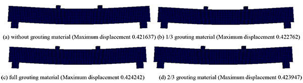
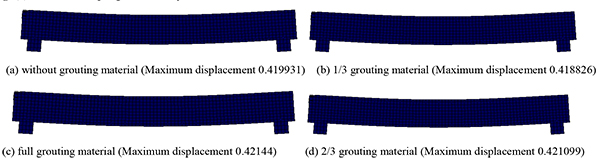
As seen from Figs. (4-6), under the concentrated, symmetrical, and uniform loads, the post-tensioned, prestressed concrete simply supported beam has different cracking deflection values with grouting materials of varied porosity. As seen in the cracking deflection values shown in Table 2, under the same load, the value of the cracking deflection increases with an increase in porosity.
4.2. Equivalent Stress Analysis
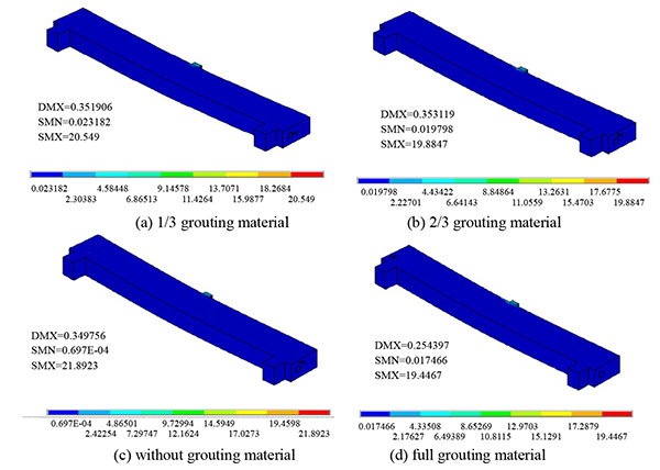
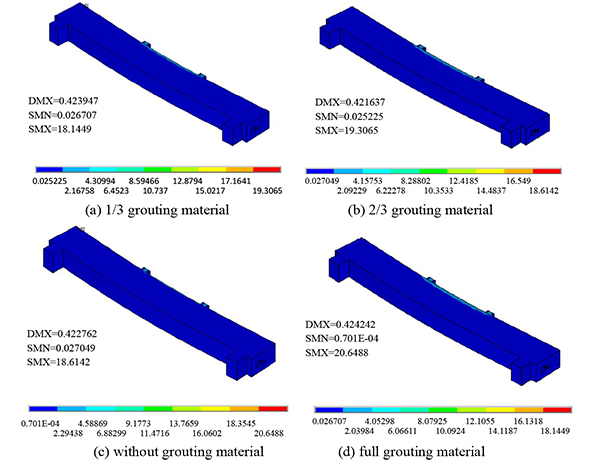
Under concentrated, symmetrical, and uniform loads, the equivalent stress nephogram of the post-tensioned, prestressed concrete beams is shown under the four conditions (the reserved void without grouting material, the reserved void for filling 1/3 grouting material, the reserved void for filling 2/3 grouting material, and the full void) in Figs. (7-9).
| Load Type | Cracking deflection value of different densities (mm) | |||
|---|---|---|---|---|
| 1/3 Grouting Material | 2/3 grouting material | without grouting material | full grouting material | |
| Concentrated Load | 0.352 | 0.353 | 0.350 | 0.354 |
| Symmetrical Load | 0.423 | 0.424 | 0.422 | 0.424 |
| Uniform Load | 0.420 | 0.421 | 0.419 | 0.421 |
As seen from Figs. (7-9), under concentrated, symmetrical, and uniform loads, the equivalent stress peak of the prestressed concrete, simply supported beam with grouting material of varied porosity appears in the upper middle position of the simply supported beam. According to the peak value of equivalent stress in Table (3), the peak value of equivalent stress decreases with an increase in the porosity of the grouting material in the same load form.
| Load Type | Equivalent stress peaks for different densities | ||||
|---|---|---|---|---|---|
| 1/3 grouting material | 2/3 grouting material | without grouting material | full grouting material | ||
| Concentrate load | 20.549 | 19.885 | 21.892 | 19.447 | |
| Symmetrical load | 19.306 | 18.614 | 20.649 | 18.145 | |
| Uniform load | 20.385 | 19.672 | 21.808 | 19.205 | |
4.3. Comparative Analysis of Results
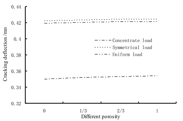
The comparison of the cracking deflection of prestressed concrete beams with grouting material of varied porosity under different load forms is shown in (Fig. 10).
As seen from Fig. (10), no matter the type of load form, the cracking deflection of the beam is increased with an increase in the porosity of the grouting material. Under the same porosity of the grouting material, the cracking deflection of the symmetrical load is larger than the cracking deflection under the uniform load. The concentrated load and cracking deflection under the concentrated load is the smallest. The greater the porosity of the grouting material of the post-tensioned, prestressed concrete beams, the higher the cracking load and bearing capacity are, and the greater the cracking deflection is. Additionally, under the concentrated load, the cracking load and deflection of the beam are the smallest.
The comparison of the equivalent stress peaks of the prestressed concrete beams with grouting material of varied porosity under different load forms is shown in Fig. (11).
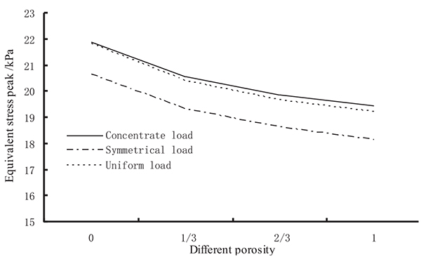
As seen from Fig. (11), no matter what kind of load forms, the peak values of the equivalent stress of the beam lessen with an increase in the porosity of the grouting material. With grouting material of the same porosity, the equivalent stress peak value of the concentrated load is always larger than that of the uniform and symmetrical loads, and the equivalent stress peak value is close to the concentrated and uniform loads.
CONCLUSION
- The cracking load, cracking deflection, and equivalent stress of the post-tensioned, prestressed concrete beams under grouting material of the same porosity vary due to the different load forms.
- Under the concentrated, symmetrical, and uniform loads, the cracking deflection of the post-tensioned, prestressed concrete beam increases with an increase in the porosity of the grouting material.
- With the increase in the porosity of the grouting material, the cracking deflection of the symmetrical load is always larger than the cracking deflection under uniform and concentrated loads, and the cracking deflection under the concentrated load is always at minimum. The results show that under a concentrated load, the cracking load of the beam is small and that a sudden, concentrated load on the upper part of the prestressed beam should be avoided.
- Under the action of concentrated, symmetrical, and uniform loads, the equivalent stress peak of post-tensioned, prestressed concrete beam decreases with an increase the porosity of the grouting material.
- With grouting material of the same porosity, the equivalent stress peak value of the concentrated load is always greater than the equivalent stress peak value under the uniform and symmetrical loads. This further illustrates the conclusions drawn (2).
CONFLICT OF INTEREST
The authors declare no conflict of interest, financial or otherwise.
ACKNOWLEDGEMENTS
This paper is a part of Science and technology project Zhejiang Traffic Quality Supervision Bureau in China (Grant number: ZJ201602).

