All published articles of this journal are available on ScienceDirect.
Synchronized Blasting Demolition of Workshop and Chimney Under Complicated Conditions
Abstract
Introduction:
For technical renovation of the thermal plant, one frame structure workshop of 50,000 m2 construction area and one reinforcement concrete chimney of 150m height shall be demolished by blasting in the same time. The engineering environment is very complicated and the accommodation space for the structures collapse is limited. Therefore, the collapse sequence, direction, scope of the structures must be accurately controlled to ensure the safe operation of the adjacent generator unit and transformer station.
Methods:
By taking technical measures of theoretical analysis and numerical simulation etc., as well as research on structures collapse process and initiation system, it puts forward the technology of bidirectional folded collapse of the workshop and it uniquely adopts the initiation system that combined with “half-second delay inside drilling” and “millisecond delay outside drilling”.
Results and Conclusion:
Additionally, by using of the integrated vibration reduction technology in combination of the blasting ruins, buffer ditch and damping ditch, it has safely accomplished the blasting demolition work in high efficiency. Besides the blasting demolition vibration signal is collected and analyzed. The success of the blasting demolition will become valuable reference to other similar works.
1. INTRODUCTION
As the sustained and rapid economic growth, and the development of urbanization infrastructure, a mass of architecture structures needs to be demolished in China. Traditionally, three schemes could be used to demolish the architecture structures:Artificial demolition, machine demolition, blasting demolition. The blasting demolition technology began to be used in china in 1958 [1], since then, the blasting demolition technology was developed gradually. Long-term practice indicates that the blasting demolition can collapse those massive architecture structures, to transform the dangerous and inefficient high-altitude jobs into the safe and efficient ground machine operations, so which is a prefect construction method, especially for high buildings, such as chimneys, cooling towers, workshops, etc.
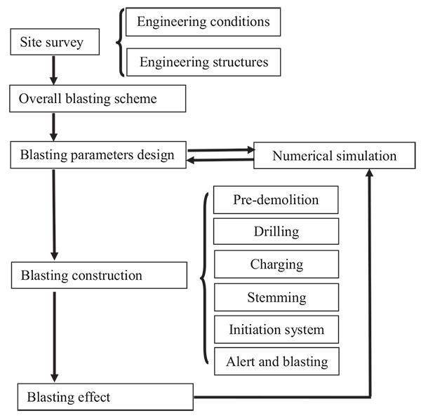
In recent years, the serious consequences of global warming are concerned widely by the international community. As early as in 11th five years plan (2006-2010), the Chinese government had announced the environmental targets of energy saving and emission reduction. In order to reduce the carbon dioxide emission, government plans to shut down some thermal plants, which cause demolition of many workshops and chimneys in the thermal plants. There are a lot of successful engineering cases of blasting demolition for the chimneys and workshops in China [2-9]. In the previous cases, however, engineers were in the purpose of safety, the workshop and chimney would be demolished separately one by one, such as, the workshops will be demolished first and the chimney may be demolished only when the workshop ruins are cleaned completely or partially [10]. But this time, in order to shorten the construction period, the client required the workshop and chimney to be demolished in the same time; it brought a huge challenge for blasting demolition. Engineers must reduce the destructive effects as much as possible during finishing blasting demolition process. If flyrock and vibration caused by blasting go beyond expectation, which causes generator set tripping and off-production incident, reactivating the generator set costs at least one million Yuan economic loss. For the comparison of the past and present cases, (Table 1). Fortunately, the numerical simulation can be helpful, to assure the blasting demolished scheme more scientifically and rationally. The paper detailed an advanced blasting demolition technology for the workshop and chimney in the thermal plant in China, Fig. (1) shows the flowchart of the blasting demolished.
| Cases | Blasting scheme | Advantages | Disadvantages |
|---|---|---|---|
| The past cases | Blasting demolished separately one by one | Low risk, don’t consider the interaction among the various architecture structures. | Low efficiency, construction period extended. |
| The present case | Blasting demolished in the same time | High efficiency, construction period shortened. | High risk, the collapse sequence, direction, scope of the dismantled building must be accurately controlled. |
2. ENGINEERING CONDITIONS
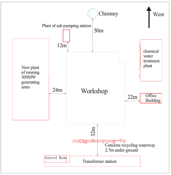
Due to technical renovation, one frame structure workshop of 50,000 m2 construction area and one reinforcement concrete chimney of 150 m height in Datang Liancheng Thermal Plant that located in Lanzhou city, Gansu Province shall be demolished in China. The engineering condition is very complex. The steam pipeline blind ditches which need be protected are only 1 m away from the bounding walls at east, south and north sides of the workshop. The chimney is on the west, 50 m away from the workshop. An ash pumping station required to be protected is on the southwest, 12 m away from the workshop. A concrete recycling waterway of 2.7 m deep underground is 23 m to the east of the workshop. At 32 m in the same direction, a transformer station is running. A running new-built 300 MW generator unit plant is 24 m to the south of the workshop. The chemical water processing workshop is 22 m to the north of the workshop. For engineering conditions, see (Fig. 2).
3. ENGINEERING STRUCTURES
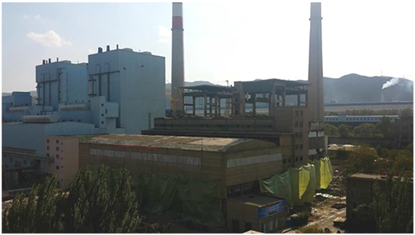
The workshop is 98.76 m long and 80 m wide. It consists of air preheater, boiler chamber, elevator shaft, milling workshop, deaerating chamber and turbine workshop. After partial pre-demolition, the 110 columns need to be demolished, and which are divided into nine different sectional dimensions, there are 11 axis in west-east direction and 11 spans in north-south direction.
The chimney is 150 m height, the body of which is cast by #250 concrete. The service ladder is arranged on the west. At 3.0 m height of the chimney, there is an ash-deposit platform and two rectangular flues with 3.2 m width and 5 m height. Outer radius of the chimney is 6.94 m and the thickness of the chimney is 0.5 m (Fig. 3) for engineering structures of the workshop and chimney.
4. TECHNICAL PROBLEMS
There are lots of successful engineering cases of workshops and chimneys demolition in China, but they generally use a construction method of separately blasting demolition. However, in order to shorten construction period, and fully reflect the safety and efficiency of the demolition blasting, the workshop and chimney are required to be demolished in the same time [11]. The key points and difficulties for this blasting demolition are as follows:
- The engineering condition is very complicated. The space for building collapse is limited, and the workshop and chimney must be demolished in the same time. The admitted collapse scope is not more than 20 meters around the workshop.
- The objects to be protected are close to the workshop and chimney, especially the running generator units and transformer station. Therefore, the impact from flyrock and vibration caused by demolition blasting [12] must be strictly controlled.
- For the large number of drilling and delay interval in the demolition blasting of the workshop, the reasonable initiation system that is critical to success must be safe and reliable [13].
- Before blasting, the numerical simulation calculation should be applied to determine the best blasting scheme and delay interval [14], so as to strictly control the collapse sequence, direction and range of the workshop and chimney.
5. OVERALL BLASTING SCHEME
The technology of cautions blasting and stage blasting is applied. In order to control the collapse scope of the workshop and reduce the blasting vibration [15], the bidirectional folded collapse scheme is applied to demolition of the workshop. The part above 31.5 m will collapse towards east directionally while the other part under 31.5m will collapse towards west directionally. It is designed of stage triangle gap (Fig. 5). For satisfaction of the need of the bidirectional folded collapse scheme and multistage delay initiation, as well as assurance the safety and reliability of the initiation system, the initiation system combined with half-second delay inside drilling and millisecond delay outside drilling is applied to demolition of the workshop.
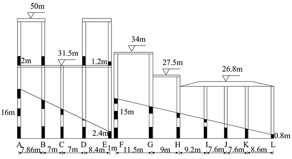
The chimney will collapse towards the blasting ruins of the workshop at east side with allowable tilting angle deviation of ±5°. Using the millisecond delay in holes, and the initiation time is 2s earlier than that of the workshop.
6. BLASTING PARAMETERS DESIGN FOR CHIMNEY
To ensure the integral stability of the chimney when it is collapsing, the ash-position platform is set outside the range of the blasting gap. The blasting gap shall be set on the elevation + 3.0 m. Gap shapes are usually rectangular, echelon, inverse echelon, triangular, etc [16]. For different gap shape, the collapse progress varies. Considering that the chimney has both rectangular flues at the elevation + 3.0 m, in order to ensure the symmetry of blasting gap, we chose a rectangular gap shape.
Blasting gap height is one of the important parameters, which should meet offset distance of chimney gravity center larger than chimney outer radius of cut position when the gap closed [17]. The gap height formula is shown in equation 1.
 |
(1) |
Where,
h = blasting gap height (m)
R = radius of blasting gap position (m)
Hc = chimney’s height of center of gravity (m)
θ = semicircle central angle of the support reserved part.
The size of blasting gap central angle directly determines the length of blasting gap, and the length of blasting gap determines the overturning moment. Bigger the blasting gap central angle is, the longer the blasting gap is and greater overturning moment is. Excessive overturning moment will accelerate buckling and settling of the reserved part, premature settling will lead to inaccurate direction for chimney collapse, especially an accident of failing to collapse. Under normal circumstances, the central angle of blasting gap is approximately between 210°~220°. By checking the overturning moment, learning from successful experiences as well as the structural characteristics of the chimney itself, the central angle of blasting gap in this project is θ = 215°, the length of blasting gap is L = (215/360)× 2 ×π× 6.94 = 26 m .
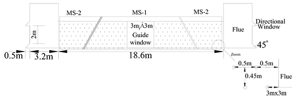
To ensure the chimney balanced and collapsed accurately according to the design direction, the directional window should be set. Considering the chimney own structural characteristics, the directional window can take advantage of the flue in this project, while a guide window should be created at the center of the blasting cut, with a size of 3.0 m in height, 3.0 m in width, as shown in Fig. (4). The hole diameter is 40 mm and hole depth is l = 0.75δ = 0.38 m. The pitch is taken hole spacing as a = δ = 0.5 m and row spacing as b = 0.9a = 0.45 m,with a total of seven rows of holes, each row with 30 holes, 210 holes arranged in total. With a selection of 2 # Rock Emulsion Explosives, which specification is Φ32 mm × 200 mm × 200 g, volume formula of charge calculation, as shown in equation 2.
 |
(2) |
Where,
Q = explosive charge (kg)
q = unit consumption of explosive(kg/m3)
a = hole spacing (m)
b = row spacing (m)
δ = wall thickness (m)
Q = qabδ =2 × 0.5 ×0.45 × 0.5 = 225 g, explosive charge set 200 g, with a continuous charging structure, 0.2 m length of charge and 0.18 m length of stemming.
With millisecond delay initiation system, we use detonators with shock-conducting tube of the delay number MS-1 and MS-2 in holes. MS-1 detonators are symmetrically arranged in holes near guide window. MS-2 detonators are symmetrically arranged in holes close to position of directional window, see (Fig. 4) for detail.
7. BLASTING PARAMETERS DESIGN FOR WORKSHOP
Workshop covers construction area of about 50,000 m2. Blasting demolition is in a fairly large scale. In order to facilitate construction organization for blasting demolition, the workshop is divided into four blasting areas. Direction and height of blasting cut as well as blast height difference back and forth are important parameters, which decide blasting objects collapse direction, overturning moment and offset angle of gravity center. Gap height is calculated based on the formula, as shown in equation 3.
 |
(3) |
Where,
h = blasting cut height (m)
K = experience coefficient, taking 1.5~2.0
B = maximum edge length on column cross section (m)
Hmin = minimum destroying height, Hmin = (30 ~ 50) d, d is diameter of vertical steel bars of columns (m).
The drilling diameter is 40 mm. To reduce the amount of drilling operations, effective control of blasting scale and effect of blasting, group hole arrangement shall be applied to this demolition blasting to blast columns in segment, horizontally drilling along both sides of column center line, increasing holes on the bottom of columns, 5 holes each group, 3 holes each group for others, 3 m space for each group, hole spacing is 0.4 m in each group. The workshop needs to blast 110 columns in total with 9 different sectional dimensions, for details of parameters see (Table 2).
| NO. | Sectional Dimensions (cm×cm) | Hole Depth (cm) | Charging Structure | Explosive Charge (g) | Bottom Explosive Charge (g) | Interval Length (cm) | Upper Explosive Charge (g) | Length of Stemming (cm) |
|---|---|---|---|---|---|---|---|---|
| 1 | 60×50 | 40 | Continuous | 150 | 150 | 0 | 0 | 25 |
| 2 | 120×50 | 95 | Interval | 300 | 200 | 30 | 100 | 35 |
| 3 | 60×60 | 40 | Continuous | 150 | 150 | 0 | 0 | 25 |
| 4 | 120×60 | 95 | Interval | 300 | 200 | 30 | 100 | 35 |
| 5 | 50×50 | 38 | Continuous | 100 | 100 | 0 | 0 | 38 |
| 6 | 110×50 | 90 | Interval | 250 | 150 | 30 | 100 | 35 |
| 7 | 80×50 | 60 | Interval | 200 | 100 | 15 | 100 | 25 |
| 8 | 80×40 | 60 | Continuous | 150 | 150 | 0 | 0 | 45 |
| 9 | 100×50 | 75 | Interval | 200 | 100 | 25 | 100 | 30 |
To reduce maximum charge per delay interval and control blasting vibration effect, we use a closed duplex initiation system combined with half-second delay in holes and millisecond delay outside holes. We respectively charge two half-second delay detonator in holes from HS-2 to HS-12, dividing the workshop into 11 half-second delay blasting areas to realize initiation district by district, then in every half-second delay blasting area we respectively use millisecond delay detonators outside holes from MS-2 to MS-5, to conduct the “One Grab” cluster connection, so as to achieve a detonating cluster by cluster, with detonators in each cluster are not more than 20, and with two MS-1 detonators for “Reverse Connection” initiation, using the Four-Way connection as a closed duplex trunk circuit. Entire initiation system is divided into multiple circuits. Finally, we use parallel-series connection between multiple circuits.
8. NUMERICAL SIMULATION
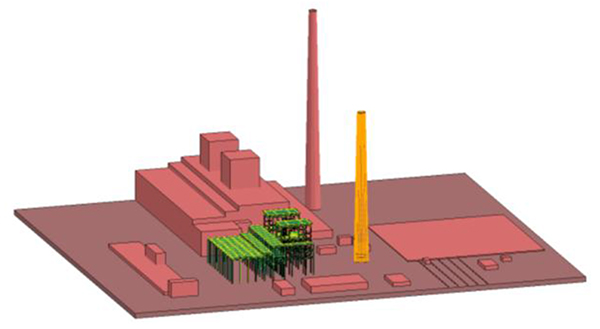
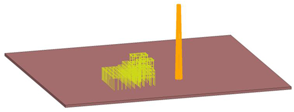
In the field of demolition blasting, numerical simulation is often implemented on blasting collapse process before blasting buildings, so as to assist blasting design. The finite element software ANSYS/LS-DYNA is applied to the numerical simulation, establishing a finite element model in ANSYS environment, using a large display dynamic analysis software LS-DYNA for solution. In this numerical simulation, a separated co-node model is used to create the reinforced concrete chimney and workshop frame structure [18], fully embodying a role of steel tensile stress in the process of structure collapse, with structural finite element model and model of steel distribution as shown in Figs. (6 and 7).
9. ANALYSIS OF STRUCTURE COLLAPSE PROCESS
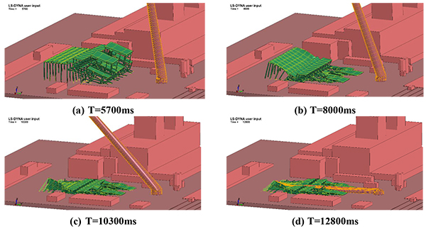
To achieve simulation of delay initiation sequence in blasting design, different components should be built. Each component can control concrete-failure time by setting * MAT_ADD_EROSION keywords to simulate the blasting process. Fig. (8) shows the simulation process of structure collapse.
9.1. Vibration Monitoring of Blasting Demolition
We used the MINI Super Graph vibrometer produced by the NOMIS Company of the United States, which can measure three seismic waves. Six measuring points in total are laid out. Points 1, 2, and 3 were arranged in the south of the workshop, which mainly monitored the impact of blasting vibration of workshop on the machine rooms while 4, 5, and 6 were laid out in the east of workshop, mainly monitoring the impact of touchdown vibration of chimney head on the transformer station. Monitoring Results of Demolition Blasting Vibration are as shown in Table 3, and R is radial vibration velocity, T is tangential vibration velocity, V is vertical vibration velocity. Typical waveform and spectra are as follows in Fig. (9).
| Monitoring Points | Distance to Workshop(m) | Peak Vibration Velocity (cm/s) | Vibration Main Frequency (Hz) | Distance to Chimney Touchdown (m) | Peak Vibration Velocity (cm/s) | Vibration Main Frequency (Hz) | ||
|---|---|---|---|---|---|---|---|---|
| 1 | 21 | R | 1.435 | 10.33 | 92.8 | R | 0.927 | 11.08 |
| T | 0.927 | 16.92 | T | 0.597 | 12.08 | |||
| V | 1.118 | 14.42 | V | 0.991 | 5.916 | |||
| 2 | 21 | R | 1.35 | 10.83 | 72 | R | 0.597 | 12 |
| T | 2.27 | 23.25 | T | 0.698 | 9.499 | |||
| V | 1.97 | 19.92 | V | 0.838 | 6.166 | |||
| 3 | 21 | R | 0.8 | 8.583 | 58.4 | R | 0.978 | 10.5 |
| T | 1.46 | 20.33 | T | 0.737 | 9.999 | |||
| V | 1.03 | 18.17 | V | 0.711 | 6.499 | |||
| 4 | 40 | R | 0.305 | 10.83 | 57.3 | R | 0.648 | 8.249 |
| T | 0.216 | 10.83 | T | 0.343 | 6.749 | |||
| V | 0.203 | 12.42 | V | 0.546 | 5.25 | |||
| 5 | 40 | R | 0.876 | 7.499 | 50 | R | 2.146 | 18.5 |
| T | 0.292 | 10.25 | T | 0.546 | 11.42 | |||
| V | 0.216 | 12.25 | V | 0.927 | 11.58 | |||
| 6 | 40 | R | 0.572 | 8.416 | 57.3 | R | 0.889 | 8.166 |
| T | 0.445 | 11 | T | 0.406 | 10.75 | |||
| V | 0.343 | 9.916 | V | 0.419 | 6.499 | |||
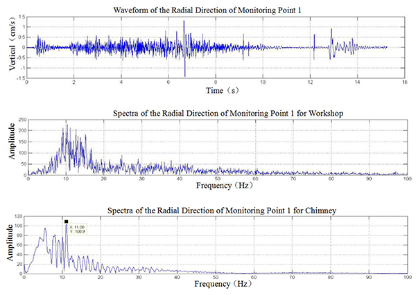
We carry out regression analysis to vibration monitoring data. From the vibration velocity attenuation formula by regression, we calculate the vibration velocity at the control rooms of generator units, the peak of which is less than 0.5 cm/s. During actual blasting process, no “trip” accident of generator units happened either.
9.2. Blasting Effect
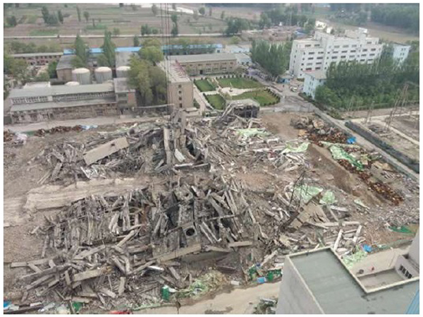
The blasting demolition effect of the workshop and chimney is completely consistent with the design; the whole collapse process takes about 13s. The full-structure disintegration is realized to form blasting ruins height of 3-6 m. The surrounding facilities are not suffered from the impact of demolition blasting. Both transformer stations in east side and generator units in south side are normally running. The blasting effect is shown in Fig. (10).
CONCLUSION
Through this practice of demolition blasting, we summed up and made the following conclusions:
- Using the technology of caution blasting and delay blasting, a safe and feasible collapse scheme was designed, to resolve the problems of complex condition and limited space of buildings collapse in thermal power plant, and to fulfill the requirements of controlling the maximum diffusion distance of blasting ruins within 20m.
- The chimney directionally collapsed to the blasting ruins of the workshop did not cause the slingshot due to bidirectional squeeze. At the same time, it is available to take advantage of the blasting ruins of the workshop to absorb the touchdown vibration of the chimney, and reduce blasting vibration effect on the surrounding buildings and facilities. In addition, by using bidirectional squeeze between the workshop and chimney can be reduced to minimize the blasting heap height and facilitate the later slag removal work.
- Thanks to the original use of the duplex closed initiation system that combined with half-second delay in drilling and millisecond delay outside drilling, it cannot only meet the requirement of multi-stage delay initiation in bidirectional folded directional collapse of the workshop, but also ensure the safety and reliability of the initiation system.
- Thanks to integrated vibration reduction technology in combination of the blasting ruins, buffer ditches and damping ditches, the demolition blasting vibration was successfully weakened. Through analyzing vibration monitoring data, it is shown that the blasting vibration amplitudes are controlled within allowable security range near the main control room and critical equipment.
- Using numerical simulation of separated co-node reinforced concrete model, we broke through the limitations of whole-model simulation, which better simulated collapse process of the workshop and chimney and the shape of the blasting heap, which provides scientific basis for blasting design of the blasting parameters.
SUGGESTIONS
Due to the limitation of construction costs, digital electronic detonators were not used in blasting demolition. Further research should be done on the application prospects of digital electronic detonators in the field of blasting demolition.
CONFLICT OF INTEREST
The authors declare no conflict of interest, financial or otherwise.
ACKNOWLEDGEMENTS
Decleared none.


