All published articles of this journal are available on ScienceDirect.

Study on Axial Compressive Behaviors and Bearing Capacity Formulas of the Composite CFST Columns
Abstract
Introduction:
With stronger confinement effects, the composite CFST column exhibits higher ultimate bearing capacity and better seismic performance than ordinary CFST column, so it has a broad application prospect in the field of structural engineering.
Methods:
This paper summarized recent researches on the axial compressive behavior of two typical composite CFST columns including the section of outer square tube-inner circular tube and the section of double circular tubes. Parameter analysis on axial compressive behavior was presented in detail according to all the experimental and theoretical results of the composite CFST columns.
Result and Conclusion:
The different axial compression ultimate bearing capacity formulas were compared based on the experimental results. Simultaneously, the insufficiencies of present work were pointed out. Lastly, suggestions for further study in this field were put forward.
1. INTRODUCTION
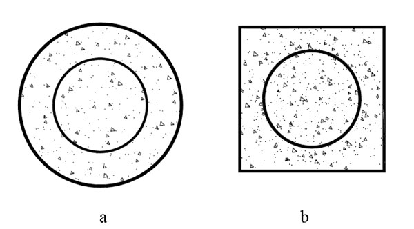
The composite concrete filled steel tube(CFST) column is a new kind of composite column improved from ordinary CFST column. Recent research mainly focused on two kinds of column sections as shown in Fig. (1). The composite column consists of an inner tubular section and an outer tubular section, fully filled with concrete. The concrete is reinforced by double circular tubes in section (a); and the concrete is reinforced by outer square tube and inner circular tube in section (b). These columns exhibit higher bearing capacity, better ductility and superior collapse resistance, so they can be widely applied in meizoseismal area [1, 2]. This paper summarized all deep explorations into the axial compressive behavior of the composite CFST columns, and axial compression performance parameters were also analyzed, and then the rationality and deficiencies of several ultimate bearing capacity formulas were verified by the calculations about the experimental results. At last, suggestions for future study were provided to perfect the theory of composite CFST columns.
2. FAILURE MECHANISM OF COMPOSITE CFST COLUMNS UNDER AXIAL COMPRESSION
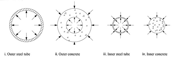
The composite CFST column has high bearing capacity due to the confining force to the core concrete supported by steel tubes. When the column is compressed under axial load, the force condition of each component can be seen in Fig. (2). As it can be seen in Fig. (2), the other components except outer tube are all under triaxial compressive stress state. So the advantages of both steel and concrete are utilized that steel members have high tensile strength and ductility, while concrete members are advantageous in compressive strength and stiffness. The whole damage process of the composite CFST column under axial compression is divided into three stages: elastic stage, elastic-plastic stage and failure stage [3].
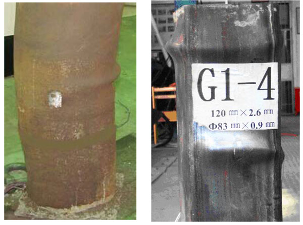
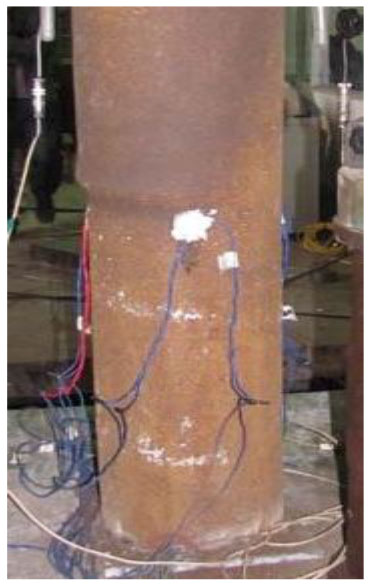
During the initiation of loading, the mutual confining force is created between inner steel tube and concrete, which can avoid the buckling of inner steel tube and the crack of concrete. At this time, both the inner steel tube and the concrete are in elastic stage. Then the crack of concrete shows the beginning of the elastic-plastic stage. With the lateral deformation coefficient increasing, the bulging force and confining force continually appear on the surfaces of different component, so the compressive strength and the elasticity modulus of the concrete increase and the stability of the steel tubes also increases due to the concrete’s lateral support. In the end, the outer steel tube tends to yield under the compressive force, while due to the duplex constraints from outer concrete and outer steel tube, the inner steel tube remains in shape and continues to provide the inner concrete with enough confinement; Along with the dramatic longitudinal strain of the column, the vertical load that assumed all the components increases slowly. When the inner steel tube approaches yielding strength, the column enters into the failure stage. The ultimate failure mode of the composite CFST column generally takes on two forms. (1). When the confinement effect is small, the local buckling of the steel tubes leads to the crush failure before the compression-shear failure of the concrete. As a result, no diagonal crack occurs on the concrete and the specimen takes on the drum-shaped failure mode as shown in Fig. (3) [4, 5]. Most composite CFST columns failed as the drum-shaped failure mode especially for the section (b). (2).When the confinement effect is large, the compression-shear failure of the concrete occurs before the local buckling of the steel tubes. The diagonal cracks are formed on the concrete compression-shear failure surfaces. As a consequence, the wedges separated by these diagonal cracks slip obliquely and the steel tubes are extruded to bucking. Then the specimen takes on the shear-shaped failure mode as shown in Fig. (4) [4]. This failure mode happened mainly for specimens with high-strength concrete.
3. PARAMETER ANALYSES ON AXIAL COMPRESSIVE BEHAVIOR OF THE COMPOSITE CFST COLUMNS
In 1997, Cai,S.H, et al. [6] firstly initiated an experiment on two composite CFST with the section (b) to investigate the axial compressive behavior of the composite CFST columns. It was concluded that the bearing capacity of the composite CFST column depends on the dual confinements from both outer and inner steel tube set on the inner concrete. Therefore, besides its own compressive strength, the inner tube can greatly enhance the confinement to the concrete.
In 2005, Pei,W.J [5] conducted an axial compression loading experiment on a total of 12 composite columns with the section (b) and the ultimate bearing capacity were obtained. By analyzing the different index of the circular steel tube, the major factors that affect the bearing capacity are the yield strength, the thickness and the diameter of the inner circular tube when the whole section area was fixed. It can be concluded that the inner circular tube improves the confinement as well as reduces the lateral deformation of the composite column, thus the elastic working range of the composite CFST columns is extended.
In 2012, Wang,W.H, et al. [7] combined the finite element method(FEM) with the orthogonal design method to analyze the mechanical performance and related parameters of the composite CFST columns with the section (b). Two evaluation index were chosen: the ratio of the bearing capacity and the cost of per unit material length. The parameters include the concrete strength, the side length of the outer square tube, the diameter of the inner circular tube, the thickness and the yield strength of the inner and outer tubes. It can be concluded that the concrete strength and the side length of the outer square tube have the greatest impact on the evaluation index. In 2013, Wang, W.H, et al. [8] also established axial compression FEM model of the composite CFST columns with the section (b) by means of ABAQUS. The numerical calculation analyzed the relationship between the area proportion of the tubes and the deformation and residual bearing capacity. The ultimate and the residual bearing capacity of the composite CFST columns keeps increasing by increasing the diameter of the circular tube. However, when the diameter is about two-thirds of the side length of square tube, the value of the ultimate bearing capacity reaches the peak value. This conclusion is also verified in theory by the achievement of Zhang (2013) [9].
In 2014, Fang,X.D, et al. [10] performed an axial compression experiment of a total of 12 composite CFST short columns with the section (a). It can be concluded that the failure modes of composite CFST columns are related with the property of the concrete, confinement of inner tube and the equivalent confinement coefficient. Define the equivalent confinement coefficient, θ= fyAs/fcAc where fy and As represent the yield strength and the area of the double circular tubes; fc and Ac represent the axial compressive strength and the area of the core concrete. The ratio of the ultimate bearing capacity and yield value increases followed by the increase of θ and the peak of the load-displacement curve tends to level. The main factors that influence the axial bearing capacity are: the compressive strength of concrete, yield strength of the steel tube, diameter ratio and the radius to thickness ratio of both steel tubes.
In 2015, Lin,S.J, et al. [4] used the semi-inverse method to gain the analytical expression of the axial compressive composite elastic stiffness of the composite CFST column with the section (a). The mechanism for the improvement of the composite stiffness compared with superposition stiffness was revealed. Parameters of the analytical expression were analyzed to find that raising the radius-to-thickness ratio of the outer tube is more effective in increasing the composite stiffness than increasing the compressive strength of concrete, yield strength of the steel tube,diameter ratio of the inner tube and the radius-to-thickness ratio of the inner steel tube respectively. While, the steel strength has no significant effect on the composite stiffness.
In general, the essential reason for the high bearing capacity of those two typical composite CFST columns are the dual confinement effects set on the core concrete. And those confinement effects can be totally described by the equivalent confinement coefficient, so all the factors related to the equivalent confinement coefficient can affect the compressive behaviors of the composite columns, such as the sizes, the strength of the inner tube, the outer tubes and the concrete, etc.
4. COMPARISONS AND ANALYSIS OF THE ULTIMATE BEARING CAPACITY FORMULAS
In recent two decades, many experts and scholars have got a wide variety of ultimate bearing capacity formulas by the experiments and the theoretical analysis on the two typical composite CFST columns mentioned above. The main research results are listed in Table 1. To testify and verify the correctness and applicability of each ultimate bearing capacity formula, different experimental data in literatures and the results calculated by each formula (As shown in Table 2 and 3) are compared.
| Theoretical method | No. | Ultimate bearing capacity formulas | Section |
|---|---|---|---|
| Limit equilibrium theory [6] | 1 |

|
a |
| Modified formulas based on limit equilibrium theory [4, 10, 11] | 2 |
|
a |
| 3 |

|
||
| 4 |

|
||
| Twin-shear unified strength theory [9, 12] | 5 |

|
a, b |
| 6 |

|
a,b | |
| The unified theory of CFST [13] | 7 |
|
a, b |
Notes:
|
|||
 are the impact parameters of the steel and concrete. The definition and the detailed calculation are seen in reference [
| No. |
D1×t1+D2×t2 mm |
fy1+fy2 MPa |
fcu MPa |
Nue kN |
Nu1 kN |
β1 |
Nu2 kN |
β2 |
Nu3 kN |
β3 |
Nu4 kN |
β4 |
Nu5 kN |
β5 |
Nu6 kN |
β6 |
Nu7 kN |
β7 | References |
|---|---|---|---|---|---|---|---|---|---|---|---|---|---|---|---|---|---|---|---|
| 1 | 219×8+102×8 | 325+331.3 | 40 | 4950 | 4691 | 0.95 | ― | ― | 4993 | 1.01 | 3998 | 0.81 | [4] | ||||||
| 2 | 219×6+102×6 | 312.5+321.7 | 40 | 4100 | 3889 | 0.95 | 3808 | 0.93 | 4069 | 0.99 | 3346 | 0.82 | |||||||
| 3 | 219×6+102×4.5 | 312.5+331.3 | 40 | 3640 | 3794 | 1.04 | ― | ― | 3926 | 1.08 | 3216 | 0.88 | |||||||
| 4 | 168×8+102×8 | 355+331.3 | 40 | 4180 | 4320 | 1.03 | ― | ― | 3903 | 0.93 | 2764 | 0.67 | |||||||
| 5 | 168×6+102×6 | 365+321.7 | 40 | 3730 | 3543 | 0.95 | 3255 | 0.87 | 3309 | 0.89 | 2544 | 0.68 | |||||||
| 6 | 168×6+102×4.5 | 325+331.3 | 40 | 3330 | 3162 | 0.96 | ― | ― | 2974 | 0.90 | 2330 | 0.70 | |||||||
| 7 | 219×8+102×8 | 325+331.3 | 71.5 | 5090 | 5713 | 1.12 | 5159 | 1.01 | 5366 | 1.05 | 5416 | 1.06 | 5296 | 1.04 | 5627 | 1.11 | 4828 | 0.95 | |
| 8 | 168×8+102×8 | 355+331.3 | 71.5 | 4266 | 4764 | 1.12 | 4205 | 0.99 | 4240 | 0.99 | 4234 | 0.99 | 3988 | 0.93 | 4236 | 0.99 | 3138 | 0.74 | |
| 9 | 219×6+102×6 | 312.5+321.7 | 84.4 | 4980 | 5276 | 1.06 | 4986 | 1.00 | 4844 | 1.00 | 4720 | 0.95 | 4685 | 0.94 | 5017 | 1.01 | 4626 | 0.93 | |
| 10 | 168×6+102×6 | 365+321.7 | 84.4 | 3925 | 4340 | 1.11 | 3757 | 0.96 | 3762 | 0.96 | 3675 | 0.94 | 3582 | 0.91 | 3824 | 0.97 | 3211 | 0.81 | |
| 11 | 219×6+102×6 | 312.5+321.7 | 97.9 | 5797 | 5656 | 0.98 | 5470 | 0.94 | 5278 | 0.91 | 5006 | 0.86 | 5024 | 0.87 | 5305 | 0.92 | 5033 | 0.87 | |
| 12 | 168×6+102×6 | 365+321.7 | 97.9 | 4250 | 4569 | 1.08 | 4020 | 0.95 | 4009 | 0.94 | 3831 | 0.90 | 3940 | 0.93 | 3980 | 0.94 | 3439 | 0.81 | |
| 13 | 132.5×3+56×3 | 465.5+465.5 | 66 | 1683 | 1908 | 1.13 | 1734 | 1.03 | 1604 | 0.95 | 1815 | 1.08 | 1599 | 0.95 | 1882 | 1.12 | 1675 | 0.99 | [11] |
| 14 | 132×3+56.1×3.2 | 465.5+465.5 | 94 | 1875 | 2286 | 1.22 | 2022 | 1.08 | 1832 | 0.98 | 1832 | 0.98 | 1824 | 0.97 | 2232 | 1.19 | 2011 | 1.07 | |
| 15 | 132×3.2+56.1×3 | 465.5+465.5 | 102 | 1925 | 2364 | 1.23 | 2066 | 1.07 | 1856 | 0.96 | 2166 | 1.12 | 1878 | 0.98 | 2307 | 1.20 | 2085 | 1.08 | |
Notes:
|
|||||||||||||||||||
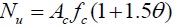
As is shown in Table 2 and 3, the results calculated by different formulas are in good agreement with those obtained from the test results on the whole. Respectively, the calculations derived by formula (1) show an error of within 5% than the experimental data for composite CFST specimens with low strength concrete, while about 11% higher(some of them exceed 20%) in terms of the ones with high strength concrete. This indicates that it is reasonable for the composite CFST short columns with low strength concrete but a slightly higher for the high strength concrete ones when the discount coefficient η takes the value of 0.9. Formula (2) considers the inner and outer confinement index to the equivalent confinement coefficient and the utilization coefficient is fitted to 1.5 by experimental data to predict the bearing capacity of the composite CFST short column with high strength concrete. As for Formula (3), on the basis of formula (1), α1, α2 are modified to 1.8 and the discount coefficientis brought down to 0.85 for the composite CFST with high-strength concrete; Formula (4) only considers the confinement from the outer steel tube by replacing the strength of the inner concrete as equivalent confinement of outer steel tube.
| No. |
B×t1+D×t2 mm |
fy1+fy2 MPa |
fc1+fc2 MPa |
 kN |
 kN |
 |
 kN |
 |
 kN |
 |
References |
|---|---|---|---|---|---|---|---|---|---|---|---|
| 1 | 180×3.62+89×2.60 | 348+314 | 105.7+87.5 | 3643 | ― | ― | 3962 | 1.09 | 3742 | 1.03 | [14] |
| 2 | 180×3.62+89×3.32 | 348+324 | 105.7+87.5 | 3583 | 3876 | 1.08 | 3736 | 1.04 | 3820 | 1.07 | |
| 3 | 180×5.40+89×2.60 | 338+314 | 105.7+87.5 | 3865 | 4142 | 1.07 | 3966 | 1.03 | 4053 | 1.05 | |
| 4 | 180×5.40+89×3.32 | 338+324 | 105.7+87.5 | 3947 | 4212 | 1.07 | 3979 | 1.01 | 4161 | 1.05 | |
| 5 | 180×3.62+89×2.60 | 348+314 | 87.5+105.7 | 3355 | 3481 | 1.04 | 3255 | 0.97 | 3447 | 1.03 | |
| 6 | 180×5.40+89×2.60 | 338+314 | 87.5+105.7 | 3814 | 3818 | 1.00 | 3565 | 0.93 | 3759 | 0.99 | |
| 7 | 180×5.40+89×3.32 | 338+324 | 87.5+105.7 | 3855 | 3746 | 0.97 | 3655 | 0.95 | 3867 | 1.00 | |
| 8 | 180×3.62+89×2.60 | 348+314 | 87.5+87.5 | 3198 | ― | ― | 3435 | 1.07 | 3357 | 1.05 | |
| 9 | 180×5.40+89×2.60 | 338+314 | 87.5+87.5 | 4021 | ― | ― | 3449 | 0.86 | 3669 | 0.91 | |
| 10 | 180×5.40+89×3.32 | 338+324 | 87.5+87.5 | 3900 | 3806 | 0.98 | 3543 | 0.91 | 3778 | 0.97 | |
| 11 | 120×2.60+58.5×1.4 | 407.5+352.5 | 35.2+35.2 | 980 | 1031 | 1.05 | 932 | 0.95 | 965 | 0.98 | [5] |
| 12 | 120×2.60+74×0.9 | 407.5+680 | 35.2+35.2 | 1040 | 1112 | 1.07 | 1032 | 0.99 | 989 | 0.95 | |
| 13 | 120×2.60+83×1.4 | 407.5+597 | 35.2+35.2 | 1080 | 1113 | 1.03 | 1027 | 0.95 | 1001 | 0.93 | |
Notes:
|
|||||||||||
 ,
,
 respectively represents the value of the ultimate bearing capacity obtained by experiment, the value of the ultimate bearing capacity calculated by formulas, the ration of
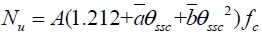
Each of the three formulas has achieved a high precision calculation results compared with the experimental data, the average value of β2, β3, β4 respectively is 1.00, 0.97, 0.99. Both formula (5) and formula (6) introduce the weighting parameter b(as for formula (6), b is implied in the strength discount coefficient βf) and side-pressure coefficient k. The specific value of the two parameters is determined by experiment; As it is suggested in reference [9, 12], the value of b, kin formula (5) and formula (6) respectively takes 0.5, 4.0 and 0.336,4.1. The results show that the suggested value is very reasonable in calculating the two typical composite CFST short columns; However, the formulas (5) and (6) are more complicate, it is inapplicable in the practical engineering. By putting forward the composite equivalent confinement coefficient θssc, formula (7) extends the unified theory of CFST to the strength calculation of the composite CFST columns [13]; From the comparisons, the following regularities can be drawn: When the value of θssc is small, the calculations shows a good agreement with the experimental date, while with the increase of θssc and the accuracy of the calculations tends to decrease especially θssc exceeds 3.0. This is because the impact parameter
 which is in front of θssc is a positive while the impact parameter
 which is in front of θssc is a negative, when θssc increases, the gain of the confinement effects is bound to decrease. To solve this problem, it is suggested that the impact parameter
should be appropriately enlarged. When the value of θssc approaches or exceeds 3.0.
which is in front of θssc is a negative, when θssc increases, the gain of the confinement effects is bound to decrease. To solve this problem, it is suggested that the impact parameter
should be appropriately enlarged. When the value of θssc approaches or exceeds 3.0.
CONCLUSION
- The compressive behavior of the two typical composite CFST columns is different from the ordinary CFST column because there are both outer and inner steel tubes to confine the concrete. During the compressive progress, yielding of the outer steel tube and the inner steel tube can determine the final failure of the composite column. The ultimate failure modes generally include drum-shaped failure and shear-shaped failure.
- The equivalent confinement coefficient can reflect the dual confinement effects set on the core concrete, so all the factors related to the equivalent confinement coefficient can affect the axial bearing capacity and compressive behaviors of the composite columns, such as the sizes, the strength of the inner tube, the outer tubes and the concrete, etc.
- Though the theories and the actual expressions of the existing several formulas differ from each other, they all have considered the confinement effects the tubes set on the core concrete. So all the formulas have gotten satisfactory results and the accuracy degree on the calculations of the confinement effects directly determines the applicability of the formulas.
- In the engineering structures, the composite CFST columns not only bear vertical load but also bear horizontal load, which is bound to generate shear force, bending moment and torque in the columns. In view of that, the further study should focus on the mechanical performance of the composite CFST columns in complicated loading states.
CONSENT FOR PUBLICATION
Not applicable.
CONFLICT OF INTEREST
The authors confirm that this article content has no conflict of interest.
AKNOWLEDGEMENTS
The authors would like to acknowledge the support provided by the Chinese National Science Foundation (Grant No. 51478004). Meanwhile, the financial support from North China University of Technology is also appreciated.

