All published articles of this journal are available on ScienceDirect.

The Bearing Capacity Calculation Method of Cracked Reinforced Concrete Column at High Temperature
Abstract
Introduction:
This paper presents results from a set of numerical studies on the cracked reinforced concrete column at high temperature.
Methods:
The macroscopic finite element model used in the accounts analysis for high temperature properties of constitutive materials. The validity of the model is established by comparing the predictions from numerical analysis with the data measured in the fire test.
Result and Conclusion:
Data from the test indicated that the temperature of rebar in column with cracks is 57% ~ 130% higher than that without cracks under the same condition, and different types of crack had significant influence on the bearing capacity of column. These results from parametric studies were utilized to propose ultimate bearing capacity of cracked reinforced concrete column.
1. INTRODUCTION
For the high compressive strength and low tensile strength of concrete, and for the reasons of concrete curing, aging deterioration and temperature change, the appearance of micro-crack on the surface of reinforced concrete structure is a common phenomenon. The bearing capacity of reinforced concrete structure can not be affected by the micro-cracks at room temperature, while it could be affected at high temperature. Therefore, it is necessary to study the reinforced concrete column with cracks at high temperature.
There are limited studies in the literature on ultimate bearing capacity of reinforced concrete column at high temperature [1-9]. Some of notable studies relating to fire performance of concrete column are reviewed here. The temperature field of reinforced concrete column with rectangular cross section was calculated by finite difference method [4]. The load capacity of column section with a certain temperature field was presented by finite element method and the effects of different parameters are analyzed. Haisheng Xu [5] has calculated the temperature field by programming and got the bearing capacity of four-side fire reinforced concrete column.
Juan Su [6] put forward a simplified calculation method of bearing capacity based on the eccentric load and lateral deflections of column. Yaozhuang Li [7], Guanglin Yuan [8] and Yuzhuo Wang [9-11] also has obtained the simplified method for calculating the load bearing capacity of four-side fire reinforced concrete column respectively.
The literature reviews above indicate that there was limited information about the bearing capacity of reinforced concrete column. Most of the previous studies involved conducted standard fire test or simplified numerical approach on the reinforced concrete column to check the adequacy of column to satisfy fire resistance ratings. The factor of crack are not considered. This paper is aimed at studying the response of cracked reinforced concrete column at high temperature.
2. NUMERICAL MODEL
2.1. Model Description
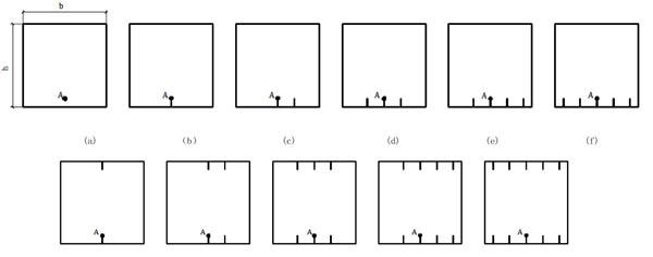
A numerical model, initially developed for tracing the fire behavior of conventional concrete column, is extended to simulate the temperature field distribution of the reinforced concrete column. The numerical model is in the form of computer program and the analysis is carried out by thermal analysis steps. As shown in Fig. (1), factors which influence the concrete column section temperature distribution mainly including cross-sectional dimension and the number of cracks. In the test, the quantity of cracks and section size are as following: section size: b×h, cracks: no cracks, one crack in one-side, two cracks in one-side, three cracks in one-side, four cracks in one-side, five cracks in one-side, one crack in two-side, two cracks in two-side, three cracks in two-side, four cracks in two-side and five cracks in two-side, a total of 11 forms. The cracks are located in the direction of the rebar. The section size of cracks is 30mm×0.3mm. The section of column is plotted in Fig. (1), and point A is the position of rebars.
The heat transfer of rebars is not considered in the calculation process. The hexahedron element is adopted in the mesh part and the solid element (C3D8) is used to model the concrete structure.
2.2. Material Properties
The temperature field of reinforced concrete column adopt the standard temperature curve (ISO-834). The properties of constituent materials, which vary with temperature, have significant influence on the thermal and structural response of the concrete column exposed to fire. For concrete, high temperature thermal and mechanical properties relations as per Eurocode [12] and provisions are built in the computer program, a user can select appropriate properties according to the specified concrete strength and aggregate type. Boundary conditions of the surface exposed to fire are convection condition and radiation condition. The convective coefficient is 25 W/(m·°C) on the exposed surface and 9 W/(m·°C) on the unexposed surface. The concrete emissivity value is 0.5, and concrete specific heat was 1000 J/(Kg·K) by ECCS recommended .
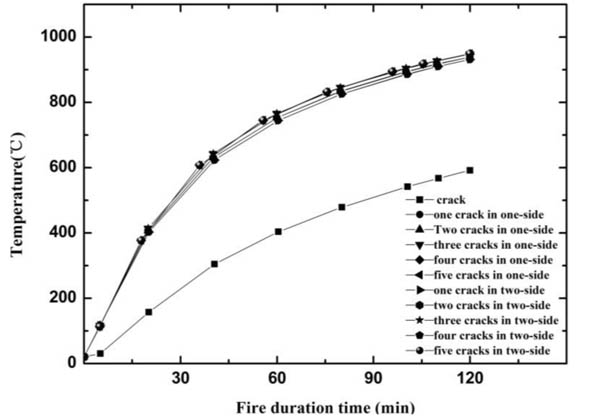
Concrete thermal conductivity is used by ECCS recommended [12], it is evaluated as:
 |
(1) |
2.3. The Distribution of Temperature Field
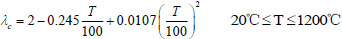
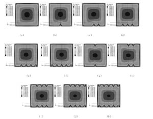
The temperature nephogram of the reinforced concrete column section with different cracks is shown in Fig. (2). Point A is considered as the reference point to analyze the influence of cracks on the temperature field. The temperature variation curve of point A with different cracks and different time is illustrated in Fig. (3). It can be seen that the temperature of reinforced concrete column increases obviously at the beginning of being exposed to fire; and then the rate of increase declined gradually with time. Following conclusions can be drawn from Fig. (3) and Table 1:
| Fire Duration Time (min) | 30 | 60 | 90 | 120 |
|---|---|---|---|---|
| The Temperature of Point A without Crack(°C) | 236.16 | 410.97 | 510.4 | 591.5 |
| The Temperature of Point A with One Crack in One-side(°C) | 527.66 | 743 | 857.3 | 931.4 |
| The Temperature of Point A with Two Cracks in One-side(°C) | 536.9 | 753.3 | 866.3 | 938.9 |
| The Temperature of Point A with Three Cracks in One-side(°C) | 543.6 | 766.3 | 877.1 | 948 |
| The Temperature of Point A with Four Cracks in One-side(°C) | 548.3 | 766.8 | 877.7 | 948.6 |
| The Temperature of Point A with Five Cracks in One-side(°C) | 548.6 | 767.4 | 878.3 | 949.1 |
| The Temperature of Point A with One Crack in Two-side(°C) | 528.6 | 743 | 857.4 | 931.6 |
| The Temperature of Point A with Two Cracks in Two-side(°C) | 536.9 | 753.5 | 866.4 | 939.1 |
| The Temperature of point A with Three Cracks in Two-side(°C) | 548.2 | 766.3 | 877.3 | 948.4 |
| The Temperature of point A with Four Cracks in Two-side(°C) | 548.3 | 766.8 | 877.8 | 948.9 |
| The Temperature of point A with Five Cracks in Two-side(°C) | 548.3 | 767.4 | 878.4 | 949.5 |
(1) The temperature of column point A with cracks is higher than that without cracks under the same conditions in Fig. (3). The temperature of the column point A with cracks is 290°C ~ 320°C higher than that without cracks under the same conditions when exposed to fire for 30 min. The temperature of the column point A with cracks is 330°C ~ 360°C higher than that without cracks under the same conditions when the time is 60 min. The temperature of the column point A with cracks is 340°C ~ 360°C higher than that without cracks under the same conditions when the time was 120 min.
(2) The temperature of column point A with different cracks is very similar under the same conditions. The temperature of the column point A with five cracks is 21°C higher than that with one crack under the same conditions when the time is 30 min. The temperature of the column point A with five cracks is 21°C higher than that with one crack under the same conditions when the time is 60 min. The temperature of the column point A with five cracks is 17°C higher than that with one crack when the time is 120 min.
(3) The temperature of column point A with cracks in two-side is almost same to that with cracks in one-side under the same conditions. When the time is 30 min, 60 min and 120 min, the temperature difference of point A between the crack in two-side and the crack in one-side is 0-5°C.
The effects of cracks on temperature field are significant. The data indicated that the column with cracks is 57% ~ 130% higher than that without cracks under the same conditions. The number of crack has less effect on the temperature. The results indicate that the column with five cracks is 2%~4% higher than that with one crack. And cracks in two-side and in one-side has very little effect on the temperature.
2.4. Isothermal Section
Based on both the finite element results and theoretical calculation, isothermal location and relationship are obtained.
When the time is 30 min, the isothermal of T3 can be calculated to be:
The column without cracks
| b3=b-2×24 h3=h-2×24 | (2) |
The column with cracks in one-side
| b3=b-2×24 h3=h-37-24 | (3) |
The column with cracks in two-side
| b3=b-2×24 h3=h-2×37 | (4) |
When the time is 60 min, the isothermal of T3 and T8 can be calculated to be:
The column without cracks
| b3=b-2×42 h3=h-2×42 | (5) |
| b8=b-2×2 h8=h-2×2 | (6) |
The column with cracks in one-side
| b3=b-2×44 h3=h-44-63 | (7) |
| b8=b-2×2 h8=h-2-9 | (8) |
The column with cracks in two-side
| b3=b-2×46 h3=h-2×63 | (9) |
| b8=b-2×2 h8=h-2×9 | (10) |
When the time is 90 min, the isothermal of T3 and T8 can be calculated to be:
The column without cracks
| b3=b-2×60 h3=h-2×60 | (11) |
| b8=b-2×9 h8=h-2×9 | (12) |
The column with cracks in one-side
| b3=b-2×64 h3=h-60-80 | (13) |
| b8=b-2×9 h8=h-9-18 | (14) |
The column with cracks in two-side
| b3=b-2×66 h3=h-2×80 | (15) |
| b8=b-2×9 h8=h-2×18 | (16) |
When the time is 120 min, the isothermal of T3 and T8 can be calculated to be:
The column without cracks
| b3=b-2×86 h3=h-2×86 | (17) |
| b8=b-2×12 h8=h-2×12 | (18) |
The column with cracks in one-side
| b3=b-2×86 h3=h-86-100 | (19) |
| b8=b-2×14 h8=h-14-30 | (20) |
The column with cracks in two-side
| b3=b-2×90 h3=h-2×100 | (21) |
| b8=b-2×14 h8=h-2×30 | (22) |
Where b3 and b8 is the equivalent width of the equivalent isotherm of 300°C and 800°C, respectively; h3 and h8 is the equivalent height of the equivalent isotherm of 300°C and 800°C, respectively.
2.5. Temperature Equivalent Section
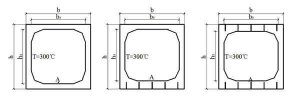
1. When the temperature of point A is lower than 300°C, the isothermal curve of 300°C is achieved. The equivalent section under four-side fire is obtained in Fig. (4).
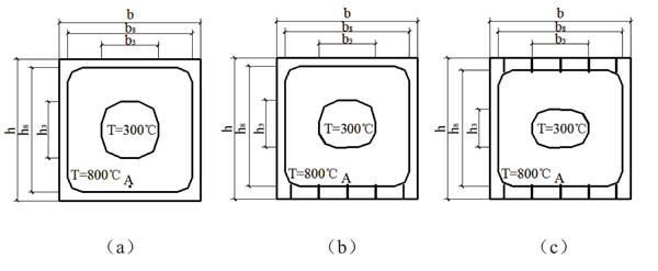
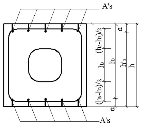
2. When the temperature of point A is higher than 300°C, the isothermal curve of 300°C and 800°C is achieved. The equivalent section under four-side fire is obtained in Fig. (5).
The effects of cracks on equivalent section are significant. The data from test indicated that the equivalent height h3 of the column with cracks is 13mm ~ 21mm higher than that without cracks, and h8 is 7mm ~ 18mm higher. The equivalent width b3, b8 of the column with cracks is 0mm ~ 4mm higher than that without cracks. The influence of cracks' number on equivalent section is significant. The results indicate that the equivalent height h3 of column with cracks in two-side is 26mm ~ 42mm higher than that without cracks, and h8 is 12mm~36mm higher. The equivalent width b3, b8 and of the column with cracks in two-side is 0mm ~ 4mm higher than that without cracks. The crack condition has little effect on the equivalent width and has obvious effect on the equivalent height.
3. THE BEARING CAPACITY FORMULA OF REINFORCED CONCRETE COLUMN EXPOSED TO FOUR-SIDE FIRE
Based on both the finite element results and theoretical calculation, assumptions of the column with cracks are adopted in the following conditions [7]:
- The temperature field of column is obtained.
- Plane section remained plane.
- No slip between the rebar and the concrete.
- The tensile strength of concrete may be neglected.
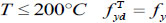
3.1. Simplified Stress-strain Relationship of Rebars at High Temperatures
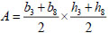
The mechanical properties of rebars  [3] at high temperature is obtained as follows:
 |
(23) |
 |
(24) |
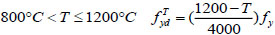 |
(25) |
 |
(26) |
Where is the design strength of rebars with cracks at high temperature, N/mm2; fy is the design strength of rebars at room temperature, N/mm2, and T is the temperature of point A, °C.
3.2. Simplified Stress-strain Relationship of Concrete at High Temperatures
The mechanical properties of concrete  [3] at high temperature is given as follows:
 |
(27) |
 |
(28) |
 |
(29) |
Where is the design strength of concrete at high temperature, N/mm2; fc is the design strength of concrete at room temperature, N/mm2.
The Bearing Capacity Formulas of Reinforced Concrete Column with Cracks at High Temperature
Based on the results of temperature field and the isotherm of 300°C and 800°C, the equivalent section in four-side fire is achieved.
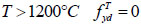
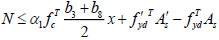
- (1). The bearing capacity formula of the reinforced concrete column with cracks under axial compression,
According to the bearing capacity of reinforced concrete column without cracks at high temperature, the bearing capacity formulas of reinforced concrete column with cracks can be calculated in Fig. (6) as follows:
 |
(30) |
 |
(31) |
- (2). The bearing capacity formula of the reinforced concrete column with cracks in eccentricity compression,
According to the bearing capacity of reinforced concrete column without cracks at high temperature, the bearing capacity formulas of reinforced concrete column with cracks is given in Fig. (7) as follows:
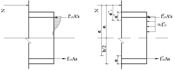
 |
(32) |
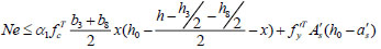 |
(33) |
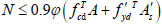
Where x is depth of the compression zone,
 .
.
4. EXAMPLE
The reinforced concrete column is drawn in Fig. (8), the section is 400 mm×500 mm, and the length is 4000mm. The design parameters of column are as follows:
as= =40mm, α1=1.0, eo=800mm,
hO=400-40=360mm.
Concrete: Ec=3×10⁴ N/mm2 ,fc=14.3N/mm2;
Rebars: Es=2×10⁵ N/mm2, fy=360 N/mm, As= =1570 mm2.
Estimate the bearing capacity of reinforced concrete column with cracks exposed to fire. The calculation results are shown in Table 2.
| Fire Duration Time(min) | Room Temper-ature | 30min | 60min | 120min | ||||||
|---|---|---|---|---|---|---|---|---|---|---|
| No Cracks | Five Cracks | Five Cracks in Two-side | No Cracks | Five Cracks | Five Cracks in Two-side | No Cracks | Five Cracks | Five Cracks in Two-side | ||
| The Bearing Capacity Under Axial Stress (kN) | 3519 | 3254 | 1588 | 1573 | 1705 | 1132 | 1098 | 1177 | 790 | 753 |
| The Bearing Capacity of Eccentricity Compression Column (kN) | 405 | 396.5 | 189.2 | 188.5 | 256.5 | 62 | 61.4 | 155.3 | 25.5 | 25.2 |
It can be obtained from Table 2 that the bearing capacity of the reinforced concrete column with cracks in one-side under axial stress is lower than that without cracks, it is reduced by 48.8%, 66% and 67% respectively when the time is 30 min, 60 min and 120 min. The bearing capacity of the column with cracks in two-side under axial stress is lower than that with cracks in one-side, it is reduced by 48.3%, 66% and 63% respectively when the time is 30 min, 60 min and 120 min. The bearing capacity formula of reinforced concrete column with cracks in one-side under eccentric load is lower than that without cracks, it is reduced by 16.4%, 24% and 47% respectively when the time is 30 min, 60 min and 120 min. The bearing capacity of the column with cracks in two-side under eccentric load is lower than that with cracks in one-side, it is reduced by 16.2%, 23% and 48.3% respectively when the time is 30 min, 60 min and 120 min.
CONCLUSION
Based on the results presented in the paper, the following conclusions can be drawn.
(1) The temperature field distribution of the reinforced concrete column with cracks at high temperature is achieved. The data indicated that the column with cracks is 57% ~ 130% higher than that without cracks under the same fire condition.
(2) The bearing capacity of the column with cracks under axial stress is 48.32%~67% lower than that without cracks; the bearing capacity of eccentricity compression column with cracks is 16.2%~47% lower than that without cracks; the bearing capacity of the column with cracks in two-side is similar to that with cracks in one-side.
CONSENT FOR PUBLICATION
Not applicable.
CONFLICT OF INTEREST
The authors declare no conflict of interest, financial or otherwise.
ANKNOWLEDGEMENTS
The authors would like to acknowledge the National Science Foundation of China (Grant No: 51378302), the Science and Technology Development of Shandong Province, China (Grant No: 2013GSF12005), the Science and Technology Development Plan of Jinan city, China (the Innovation Plan of Universities and research institutes. Grant No: 201303085), the Research and development program of Shandong Province’s university (Grant No: J11LE06), the Science and Technology project of Housing and Urban Construction Ministry (Grant No: 2013-K2-39).

