All published articles of this journal are available on ScienceDirect.

Experimental Study on Shear Performance of Innovated Precast Shear Walls with Different Yield Strength Grades of Reinforcements
Authors Info & Affiliations
Abstract
Introduction:
The hollow slab shear wall structure is a new type of shear wall structure by industrial production.
Objective:
To study the mechanical performance of the new-typed walls with different horizontal bars strength, quasi-static tests were carried out for two hollow slab shear walls.
Result and Conclusion:
The results show that strength of horizontal bars has a little influence on the hysteretic behavior and the deformation ability. While the decrease of the strength of horizontal bars can increase the yield displacement and the peak displacement of the hollow slab shear walls. The hollow slab shear wall structure has good deformation capacity, and the brittle shear failure can be avoided.
1. INTRODUCTION
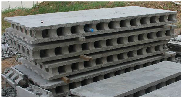
Precast concrete shear wall is a residential building structure system suitable for housing industrialization [1, 2]. An innovated precast concrete shear wall is present, which is assembled by precast two-way hollow slabs [3-5]. In the new type precast concrete shear wall structure the precast two-way hollow slabs can be used as formwork, and then connected by steel bars in hollows, and poured with concrete, finally forming whole structure.
The precast two-way hollow slab used in the new type precast concrete shear wall structure, has longitudinal circular holes and lateral square holes, which is shown in Fig. (1). The vertical reinforcing steel bars of precast concrete shear wall are set in the precast two-way hollow slab, which is C8@200. There is only steel wire in the horizontal direction of the precast two-way hollow slab. The horizontal steel bars of precast concrete shear wall are set in lateral holes of precast two-way hollow slab to provide shear capacity and connect different assembled elements at the same time. In order to study the influence of the horizontal reinforcing steel bars on the mechanical behaviors of new type precast concrete shear wall, two precast concrete shear wall specimens were designed and tested quasi-statically under low cyclic lateral loads. The effects of different yield strength grades reinforcements was investigated, and it can provide some references for engineering application of the new type structure.
2. TEST DESIGN
2.1. Test Specimen Information
Specimen size and situation of reinforcement are shown in Fig. (2), and the shadow parts in it represent precast concrete. Two new type precast concrete shear walls were designed, named 2-SW1 and 2-SW5-H. The specimen was composed of loading beam, middle shear wall and foundation beam. The size of loading beam was 290mm in width and 200mm in height; the foundation beam was 500mm in width and 650mm in height; the middle shear wall was 1600mm in width and 200mm in thickness which included precast two-way hollow slab, edge member and cast-in concrete in the hollows. The length of edge member was 210mm along the wall width. Their shear span ratios were 1.5 and the corresponding heights were 2400mm.
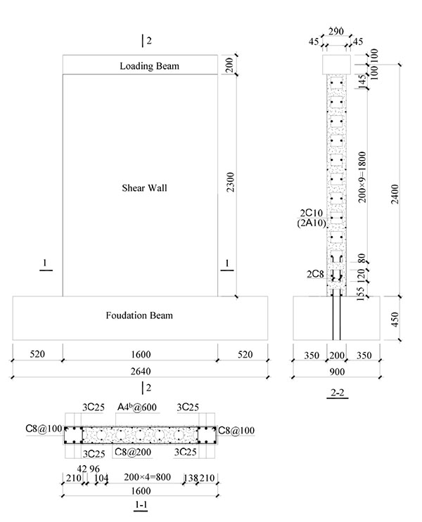
According to the design principle of strong bending and weak shear, the vertical reinforcement of edge member was high-tensile deformed steel bars of 25mm diameter respectively. Its stirrups were high-tensile deformed steel bars of 8mm diameter, and the distance was 100mm. The difference of specimen 2-SW1 and specimen 2-SW5-H is the yield strength grade of horizontal reinforcements which were set in the lateral holes. The yield strength grade of horizontal reinforcements was high-tensile in specimen 2-SW1, and was low-tensile in specimen. The diameter of the horizontal steel bar in the two specimens was 10mm.
2.2. Specimens Fabricating
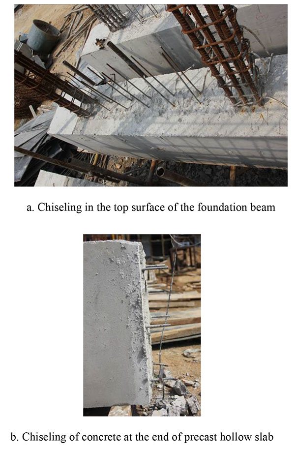
When the specimens fabricating, the foundation beam was made at first. The longitudinal steel bars of boundary member and vertical inserted reinforcement were pre-buried in the foundation beam. There were 2C 8 in the vertical hole of precast hollow slab to connect the foundation beam and shear wall which elongated to 410mm from the top surface of foundation beam. When the concrete strength reached the design strength, the top surface of foundation would be roughened to make the coarse aggregate of foundation watched. It is shown in Fig. (3a). And then, the precast hollow slab was hoisted. In order to ensure the effective connection between the precast hollow slab and loading beam, the precast concrete of 100mm length was chiseled at the top of precast hollow slab and the vertical steel bars were inserted in loading beam. It is shown in Fig. (3b) that horizontal bars were replaced in the horizontal holes of precast hollow slab and the ends of them were inserted to boundary element to make the effective connection between precast hollow slab and boundary beam. At last, templates of loading beam and boundary elements were supported and the concrete was poured in the hole.
2.3. Material Characteristics
The concrete standard test cubes were reserved during making the walls. The cubic compressive strength of concrete [6] was measured at the test day, which is shown in Table 1. The measured yield strength, ultimate strength and the elongation of reinforcement can be observed in Table 2.
| Number | Compressive Strength of Concrete fcu,m/MPa | |
|---|---|---|
| Post-cast concrete | Precast concrete | |
| 2-SW1 | 43.6 | 42.2 |
| 2-SW5-H | 40.8 | 42.2 |
| Reinforcement | Position | fy/MPa | fu/MPa |
|---|---|---|---|
| C 8 | Vertical dowel bar, vertical distribution bar | 370 | 567 |
| stirrup | 381 | 569 | |
| C 10 | Horizontal bar | 356 | 542 |
| A10 | 338 | 504 | |
| C 25 | Longitudinal bar in the boundary elements | 447 | 601 |
2.4. The Method of Loading and Measurement
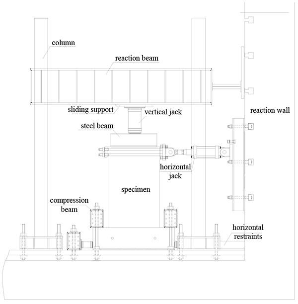
The test setup is shown in Fig. (4). During the test, the vertical load was firstly applied by a vertical jack and the vertical load kept constant. At the same time, the horizontal load was applied by a horizontal jack. The loading method of horizontal load was firstly the load-displacement control [7], with the differential of 250kN, and each load was applied cyclically once. After the diagonal cracks occurred on the shear wall, displacement control was applied with every subsequent cycle repeated twice. The controlled displacement was chosen as the measured crack displacement value. After the peak load, the differential of the control displacement changed double after the peak load.
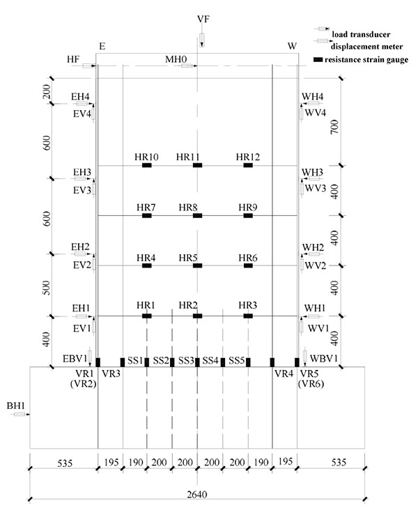
The measurement of displacements and strains is shown in Fig. (5). 12 displacement transducers were replaced to measure the horizontal displacement of the loading point, the horizontal displacements along different heights of the wall, and the rotation and translation of the foundation beam. Meanwhile, 27 electric resistance strain gauges were replaced to measure the strain’s variation of the horizontal bars, the vertical dowel bars, and the longitudinal bars in the boundary elements. All test data was timely monitored and collected by DH3816N system.
3. THE FAILURE PHENOMNA
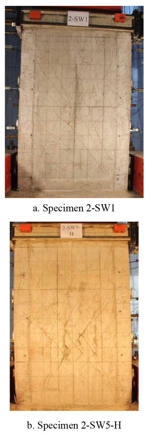
The failure process and damage characteristics of specimen 2-SW5-H was similar to specimen 2-SW1. At first, there were horizontal cracks occurring along the root of boundary element in the shear wall. And then, diagonal cracks appeared at the bottom of shear wall. As the displacement increase, the number of diagonal cracks increased and there were some horizontal cracks appearing on the boundary element. Then, two-direction diagonal cracks crossed each other to divides the precast concrete to some different diamond regions. After peaking load, interfaces between cast-in-situ destroyed and the diamond regions occurred. The destroyed region was concentrated in the middle of shear wall. At last, the precast concrete flaked away heavily and the vertical bearing capacity was lost. So the test was over.
The damage characteristics of specimens are shown in Fig. (6). Comparing to specimen 2-SW1, the yield strength of horizontal steel bars in specimen 2-SW5-H was decreased to weak dowel action of horizontal steel bars because of diagonal cracks. The width and region of diagonal cracks were more serious than specimen 2-SW1.
4. TEST RESULT ANALISIS
4.1. Top Lateral Load-displacement Hysteretic Loops of Specimens
The top lateral load-displacement hysteretic loops of specimens are shown in Fig. (7), where vertical axis is shear-compression ratio P/fcbh0, and lateral axis is the displacement angle of loading point. According to the curves, it can be concluded that:
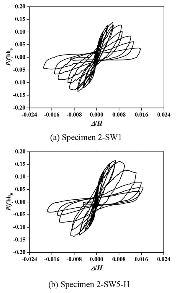
- At the initial stages of the test, the number of crack was less and the width was very tiny. Bending deformation could be recovered, with low residual deformation. Therefore, the hysteretic loops were described as straight lines.
- With the increasing of lateral load, the number and width of diagonal cracks increased. Bending deformation could not be recovered and slip deformation in the root of shear wall increased to aggravate the narrow hysteretic characteristic.
- The top lateral load-displacement hysteretic loop of specimen 2-SW1 was similar to specimen 2-SW5-H. The yield strength of horizontal steel bars had little influence on the characteristic hysteretic of the new-type shear wall.
4.2. Shear Capacity
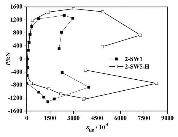
The peak loads of specimen 2-SW1 and specimen 2-SW5-H were 1330kN and 1393kN respectively. The shear-compression ratio was 0.137 and 0.148 respectively. Fig. (8) shows the strain of horizontal steel bars of specimen in the position HR4. It can be gained that the strain of horizontal steel bar in specimen 2-SW5-H was obviously higher than specimen 2-SW1 in the same position.
4.3. Deformation Capacity
Ductility: The displacement of yield point, peak point and limit point and the displacement ductility coefficient are shown in Table 3, where yield point is selected by geometrograph, and limit point is the state point which is the horizontal load decreased to the peak load at 85% on the skeleton curve. It can be seen that, the displacement ductility coefficient of the two specimen was close to or more than 4, and the new-type shear walls have good ductility. The yield displacement and peak displacement of specimen 2-SW5-H were more than specimen 2-SW1 to prove that decreasing the yield strength of horizontal steel bar can raise the deformability.
| Specimen Number | Direction | Yield Displacement/mm | Peak Displacement/mm | Limit Displacement/mm | Displacement Ductility Coefficient | |||
|---|---|---|---|---|---|---|---|---|
| Δy | average | ΔP | average | Δu | average | |||
| 2-SW1 | push | 6.39 | 5.37 | 16.17 | 15.05 | 23.09 | 24.13 | 4.50 |
| pull | 4.34 | 13.93 | 25.17 | |||||
| 2-SW5-H | push | 6.12 | 6.67 | 22.23 | 19.20 | 25.79 | 25.78 | 3.87 |
| pull | 7.21 | 16.16 | 25.76 | |||||
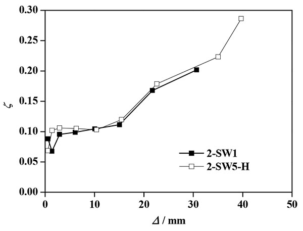
Energy Dissipation: Equivalent viscous damping coefficients-displacement curves are shown in Fig. (9). By curves comparison, it can be seen that the curves of specimen 2-SW1 and specimen 2-SW5-H basically in coincidence to prove that the energy dissipation capacity of two specimens was equally and the yield strength of horizontal steel bars had little influence on the energy dissipation capacity of new-type shear wall.
CONCLUSION
Quasi-stoical tests under low cyclic lateral loads were conducted on two shear walls built with different yield strength horizontal steel bars. The shear behavior was studied. Based on these studies, the following conclusions were obtained as follows.
- The new-type of shear walls have adequate deformability and can avoid the brittle shear failure.
- The yield strength of horizontal steel bars had little influence on the failure process, damage characteristics, characteristic hysteretic, deformation capacity of new-type shear wall.
- As the yield strength of horizontal steel bars decreases, the width of diagonal crack, yield displacement, peaking displacement will increase.
CONSENT FOR PUBLICATION
Not applicable.
CONFLICT OF INTEREST
The authors confirm that this article content has no conflict of interest.
ACKNOWLEDGEMENTS
The authors are grateful to the support of National Science Foundation of China (Grant No. 51378450, 51508490) and the Project of Shandong Province Higher Educational Science and Technology Program (Grant No. J13LG09).

