All published articles of this journal are available on ScienceDirect.

Experimental Study on New-typed Prefabricated Shear Walls with Vertical Joint Under Different Shear Span Ratio
Abstract
Objective:
To study the connection behavior of the vertical joint and the effect of shear span ratio on the mechanical behavior of the new-typed prefabricated shear walls with the vertical joint, quasi-static tests for three walls have been carried out.
Results and Conclusion:
The results show that the shear span ratio has significant effect on the mechanical behavior of the new-typed prefabricated shear walls, and the new-typed prefabricated shear walls have good ductility, all the ductility factors are greater than 4.0. The study also proves that the construction of the vertical joint is reasonable and its connection property is reliable. The vertical joint which can ensure the effective connection between different assembly units on horizontal direction can be used to guide the practical engineering.
1. INTRODUCTION
Compared with the traditional cast-in-place concrete structures, the precast concrete structures have advantages of rapid construction speed, less resource consumption and good construction quality etc. The use of precast concrete structures becomes an effective means to realize the housing industrialization gradually [1, 2]. The precast concrete shear wall structure has good seismic behavior and plays an important role in precast concrete structures, the study and usage of which are considered as a key direction to promote the housing industrialization in China. As a core technology of the precast concrete shear wall structures, the connection technology has been a research emphasis at home. To develop a new-type of prefabricated shear wall structure with a reasonable and reliable connection construction is an urgent issue in the present researches [3-8].
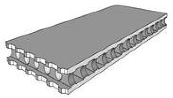
The precast concrete slab is the assembly unit of the new-type of prefabricated shear wall (hereinafter referred to as NSW) developed by Institute of Architectural Design of Tsinghua University and Yantai University, which is shown in
Fig. (1). The slab has two holes, an integral structure can be formed through placing reinforcement and pouring concrete in the hollow slab holes. The vertical joint connects the different assembly units, which consists of the interface between the cast-in-place and precast concrete, horizontal reinforcements and cast-in-place concrete. Tests of walls under the same shear span ratio indicate that the vertical joint has good connection behavior, and can ensure the integrity between different assembly units [3-6]. But reports about the effect of the shear span ratio on the connection behavior of the vertical joint have not been published so far, have been designed here. Quasi-static tests for three NSW specimens with vertical joint under different shear span ratios have been carried out to study the connection behavior of the vertical joint, which can provide references for the engineering application of the NSWs.
2. GENERAL SITUATION OF TEST
2.1. Design of Specimens
Fig. (2) shows the dimensions of specimens, three NSWs which include 2-DW1, 2-DW4-L1 and 2-DW5-L2 are designed, the shaded area is the precast concrete. The specimens’ section size is 1600mm×200mm, which consists of the wall in the middle and boundary elements. The size of boundary element is 200mm×200mm, the wall in the middle is made up of a 20mm wide vertical joint, 2 precast slabs and cast-in-place concrete in the holes. 2-DW1 is a standard specimen, the shear span ratio of which is 1.5, the height between the loading point and the bottom of the specimen is 2400mm. The shear span ratios of specimens 2-DW4-L1 and 2-DW5-L2 are 1.5 and 2.0 respectively, the heights of which are 1600mm and 3200mm correspondingly.
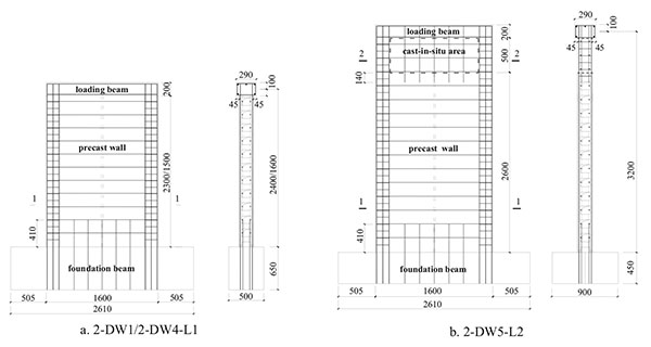
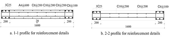
Considering the concept of ‘strong bending capacity and weak shear capacity’, the boundary elements are reinforced with 6 high-tensile longitudinal rebars of 25mm diameter and hooped with the high-tensile rebars of 8mm diameter at 100mm spacing. High-tensile rebars of 8mm diameter at 200mm are placed in precast slabs as the vertical distribution reinforcements; high-tensile rebars of 10mm diameter at 200mm spacing are placed in each transverse hole. To ensure the effective connection between the precast concrete slabs and the foundation beam, double high-tensile rebars of 8mm diameter are placed and inserted into each vertical hole of the precast concrete slab with a length of 410mm.The reinforcement details of the specimens are shown in Fig. (3).
2.2. Production of Specimens
The standard dimension of the precast concrete slab is 2700mm×1180mm×200mm, and the side-length of its transverse holes is 120mm, the diameter of the longitudinal holes is 104mm,the center to center spacing of all the holes is 200mm.The precast slabs were produced in factory and transported to construction site. In the production of specimens, the precast slabs were cut into two parts along the longitudinal central axis, and the parts were rotated around the vertical direction for 180o to make the two longitudinal edges of slab face to face, and the edges were chiseled .The vertical distribution rebars were anchored 100mm into the upside wall or loading beam to ensure the connection behavior between the precast slabs and upside wall or loading beam.
The height of 2-DW5-L2 is 3200mm.500mm height cast-in-place concrete was set at the top of the wall to meet the demand of design. The horizontal reinforcements were double high-tensile of 10mm diameter at 200mm placing, and the vertical distribution reinforcements were high-tensile of 8mm diameter at 200mm placing in the cast-in-place concrete wall.
Firstly, place the reinforcement cages of foundation beam and the reinforcements of boundary elements and splice rebars, then pour concrete. When the concrete reached its designed strength, chisel the concrete at the top of the foundation beam to ensure the connection between the upside wall and the foundation beam is effective.
2.3. Loading Method
Low cyclic lateral loading with constant axial load was applied in the test. The test axial compression ratio was 0.15. The axial load was firstly applied in the test, the lateral load was applied after the axial load remained constant. The lateral load value was positive when the specimen was pulled and was negative when pushed. The lateral load was controlled by load-displacement control system:in the loading stage controlled by load, every cycle was repeated once. The load rank differences are 300kN, 250kN and 200kN respectively for the specimens with the shear span ratios which are equal to 1.0, 1.5 and 2.0. The displacement control was applied after the first diagonal crack occurred: every cycle was repeated twice, and the displacement rank difference is twice the corresponding displacement of the crack load, loading was continued until the specimen failed and the test was thought to be finished [9].
2.4. Measurement Method
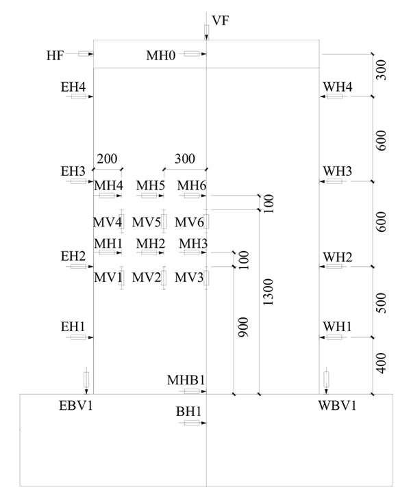
Horizontal load and axial load were measured by using force sensors. The measurement point MH0 was used to measure the top lateral displacement (the height of the top point of specimen was same as the lateral loading point). The points EH5~EH5 and WH1~WH5 were used to measure the lateral displacement of different heights on both sides of the wall. The point MHB1 was used to measure the horizontal slippage between the precast slab and the foundation beam. The point BH1 was used to measure the horizontal slippage of the foundation beam. The points EBV1 and WBV1 were used to measure the lift displacement on both sides of the foundation beam. To measure the relative displacement of interfaces between the precast slabs and boundary elements, the two parts on the sides of vertical joint and the concrete between the vertical cracks, the points MH1~MH6 and MV1~MV6 were used to measure the lateral opening width of the interfaces and the vertical relative deformation respectively. Take the standard specimen 2-DW1 as an example, measure points are shown in Fig. (4). Meanwhile, the strains of boundary elements’ longitudinal reinforcements, splice reinforcements in the foundation beam, and horizontal distribution reinforcements were measured by placing strain gauges.
3. TEXT PHENOMEN
Considering the concept of ‘strong bending capacity and weak shear capacity’, the specimens experienced failure processes of the successively occurring horizontal cracks at two toes of the walls, the diagonal cracks, the vertical macro-cracks and the vertical crack along the vertical joint. The failure process and failure mode were similar. At the peak value, the horizontal bars in the precast slabs yielded, the longitudinal bars of the boundary members remained elastic, and the concrete of toes of the wall still remained intact. The failure process was introduced for example of the specimen 2-DW1, as shown in Fig. (5).

2-DW1: The shear span ratio of 2-DW1 is 1.5, the axial load of which is 1450kN. Fine horizontal cracks occurred at toes of the wall at load +455kN.Short and thin vertical cracks occurred along the vertical joint at the load -730kN, while the width was about 0.1mm. The first diagonal crack occurred at the load +720kN; after that, multi-strip horizontal cracks and diagonal cracks occurred and extended from bottom to top with the increase of load, the width of the vertical crack increased to 0.4mm gradually. The first macro-crack along the longitudinal distribution reinforcement occurred at the top drift ratio +1/114, the others occurred successively with the increase of load. The crack between the boundary element and the precast slab occurred and extended upward and downward at the top drift ratio -1/114.The concrete at the cracks peeled off slightly when the load was close to the peak load. When the top drift ratio reached -1/117 and +1/101, the concrete around the macro-cracks peeled off obviously, the relative deformation between both side of cracks increased suddenly, the crack width was about 0.9mm, and the horizontal reinforcements yielded at the peak load -1271kN and +1253kN.When the top drift ratio reached 1/73, the concrete at middle-low part peeled off seriously, the relative deformation increased sustainably, the bottom horizontal crack decreased gradually and the strain of boundary elements’ longitudinal reinforcements decreased. When the top drift ratio reached about 1/45, the bearing capacity of specimen was lost, the specimen failed seriously and the test was finished.
The shear span ratios of the specimen 2-DW4-L1 and 2-DW5-L2 are 1.0 and 2.0 respectively, their axial load are 1521kN and 1575kN respectively.
2-DW4-L1: Compared with the specimen 2-DW1, the diagonal cracks covered all the wall body before the peak point for the specimen 2-DW4-L1, the width of the vertical crack increased slowly. When the top drift ratio reached -1/125 and +1/207, the lateral load reached the peak value, and the width of the vertical crack was about
0.8mm. After the peak point, the bearing capacity decreased obviously. With the increase of the control displacement, the relative deformation between the both sides of the vertical crack increased gradually, the concrete at the middle of the wall peeled off seriously. When the top drift ratio reached -1/49, the longitudinal reinforcement at the toes of the wall yielded, and the concrete was crushed and the test was finished.
2-DW5-L2: Concrete failure region of the specimen 2-DW5-L2 was concentrated on the middle-bottom of the wall. When the top drift ratio reached +1/93, the vertical crack occurred at top of the vertical joint, the crack width was about 0.1mm, multi-strip short-thin cross diagonal cracks occurred along the longitudinal distribution reinforcements of the precast slab. When the top drift ratio reached -1/51 and +1/68, the load reached the peak point, the vertical crack width increased to about 1.0mm.
When the top drift ratio reached -1/46 and +1/51, the concrete at the vertical cracks peeled off seriously, the lateral load decreased to 85% of the peak value. With the increase of the lateral displacement, concrete in the rhombic region formed by cross diagonal cracks in the middle of the wall peeled off and local concrete at the toes of the wall was crushed. When the top drift ratio reached about 1/43, which was much larger than that of the 2-DW1, the load bearing capacity lost and the test was finished.
4. ANALYSIS OF TEST RESULTS
4.1. The Hysteretic Curves
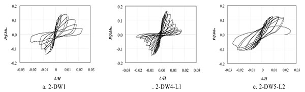
The top lateral force-displacement hysteretic curves of specimens are shown in Fig. (6). The horizontal axis of the curves is the drift ratio measured at the loading point Δ/H, and the vertical axis is the shear compression ratio P/fcbho. From the curves, it could be found that:
- The hysteretic curves of NSWs are nearly a straight line at the initial loading stage, the specimens almost have no residual deformation and remain elastic.
- With the increase in the lateral load, the quantity of cracks increases and the cracks can not be closed completely when unloading which leads to the increase of residual deformation and the pinching of the hysteretic loops.
- Because the proportion of the shear deformation in the total deformation decreases gradually, the pinching of the hysteretic loops is relieved gradually with the increase of shear span ratio.
4.2. The Deformation Capacity
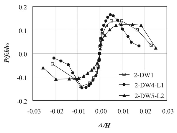
The top lateral load-displacement skeleton curves of specimens are shown in Fig. (7). The peak load, the peak displacement and the displacement ductility factor [10] are shown in Table 1. It could be found that:
| Specimens | Direaction | Peak point | Ductility factor | |||
|---|---|---|---|---|---|---|
| Pm/kN | Pm/fcbho | Δm | θm | |||
| 2-DW1 | push | 1271 | 0.1393 | 20.51 | 1/117 | 6.18 |
| pull | 1253 | 23.85 | 1/101 | |||
| 2-DW4-L1 | push | 1402 | 0.1558 | 12.79 | 1/125 | 4.22 |
| pull | 1561 | 7.73 | 1/207 | |||
| 2-DW5-L2 | push | 1082 | 0.1166 | 62.81 | 1/51 | 6.96 |
| pull | 1213 | 46.80 | 1/68 | |||
- The shear span ratio is a significant factor which can affect the mechanical behavior of the NSWs. The bearing capacity decreases obviously with the increase of the shear span ratio. Compared with specimen 2-DW1, the bearing capacity of 2-DW4-L1 increases to 11.8% due to the fact that the shear span ratio decreases to 33.3%,and the bearing capacity of 2-DW5-L2 decreases to 16.2% because the shear span ratio increases to 33.3%.
- The effect of the shear span ratio on the deformation ability of the NSWs is obvious. The peak drift ratio increases significantly with the increase in the shear span ratio.
- The stiffness of the walls increases significantly before the peak point with the increase in the shear span ratio.
- All the ductility factors of specimens are greater than 4.0, the specimens have good deformability.
4.3. The Connection Behavior of the Vertical Joint
The key technology of the new-typed prefabricated shear wall structure is the connection between different assembly units. The connection performance of the vertical joint under different shear span ratios is the research emphasis in this article.

Fig. (8) shows the lateral opening relative deformation along the vertical joint at the drift ratio 1/1000,1/200 and 1/100. It could be found that: when the drift ratio reaches 1/1000, the walls remain elastic, the lateral relative deformations are very tiny, which are less than 0.12mm.When the drift ratio reached 1/200, the horizontal reinforcements yield, the lateral relative deformation increases gradually, and the biggest relative deformation is 0.62mm.When the drift ratio reaches 1/100, due to failure of the measure equipment, the lateral relative deformations of 2-DW4-L1 cannot be measured, the horizontal relative deformations of others are less than 1.0mm. The lateral relative deformations along the vertical joints changes slightly in the test progress. It is shown that the vertical joint can ensure the connection between different assembly units in the horizontal direction, the proposed construction of the vertical joint is reasonable and reliable. The effect of different shear span ratios on the connection behavior of the vertical joint is not significant.
CONCLUSION
Three new-typed prefabricated shear walls with vertical joint under different shear span ratios were quasi-statically tested. The hysterestic performance, the deformation capacity and the connection performance of the vertical joint were analyzed. It is concluded that:
- The shear span ratio is the significant factor, which affects the mechanical behavior of the NSWs. The deformation capacity increases significantly and the shear bearing capacity deceases with the increase in the shear span ratio.
- The NSWs with the vertical joint have good ductility.
- The construction of vertical joint is reasonable and reliable, which can ensure the horizontal connection effectively between different assembly units, and can be used to guide the practical engineering.
CONSENT FOR PUBLICATION
Not applicable.
CONFLICT OF INTEREST
The authors confirm that this article content has no conflict of interest.
ACKNOWLEDGEMENTS
The authors are grateful to the support of National Science Foundation of China (Grant No. 51378450) and the Project of Shandong Province Higher Educational Science and Technology Program (Grant No. J13LG09).

