All published articles of this journal are available on ScienceDirect.

Monitoring of Dynamic Strain Response in Concrete Structure Based on Piezoelectric Sensors
Abstract
Background:
In this study, piezoelectric sensors were embedded into concrete structures to monitor dynamic response. The embedded piezoelectric sensors had sensitive frequency and linear response.
Objective:
In the experiment, two loading conditions were applied to the concrete cantilever beam and concrete frame. The dynamic properties could be monitored using the embedded sensors and the damage could also be identified.
1. INTRODUCTION
Due to the dynamic load, there are some unpredictable stresses which influence the durability and safety of structures. Therefore, it is significant to conduct the real-time and effective monitoring for structures under dynamic loading condition. The piezoelectric ceramic has many advantages such as fast response, low cost, simple processing and so on [1]. Thus, the use of piezoelectric ceramic is increasing widely in structural health monitoring.
There are good practical foundations for the application of dynamic piezoelectric ceramic smart materials in the monitoring of concrete structures. When the piezoelectric smart material subject to some external effects, such as force, temperature and so on, it will generate the corresponding mechanical deformation and internal charge relative slip, which leads to the positive and negative charges in the two surfaces of elements. This phenomenon is the piezoelectric effect. The charge density in the surface of the piezoelectric material is proportional to its deformation caused by external force [2-5]. Based on this principle, many scholars monitor changes of internal force and frequency in structures using piezoelectric sensors. In the experiment of steel beam with simulated damage, the decline of vibration frequency and stiffness of the structure was monitored with piezoelectric impedance method. In addition, the test proved that the real part of the electric admittance value was more sensitive to the discrimination of the structural damage than the imaginary part [6]. Based on wavelet packet damage index, Song [7] monitored the relationship between structural damage degree and load value using piezoelectric sensors. The results showed that the linear relationship between structural damage degree and load value could be monitored effectively with piezoelectric materials.
In many experiments, the piezoelectric sensors were attached to the surfaces of the specimen. In order to monitor dynamic strain response of concrete structures, the piezoelectric sensors were embedded inside the concrete. The embedded piezoelectric sensors have the advantages of good durability, strong anti-interference and high sensitivity. In this paper, the application of embedded piezoelectric sensors in dynamic monitoring of concrete cantilever beam and concrete frame was studied.
2. PIEZOELECTRIC CERAMIC SENSOR AND ITS CALIBRATION
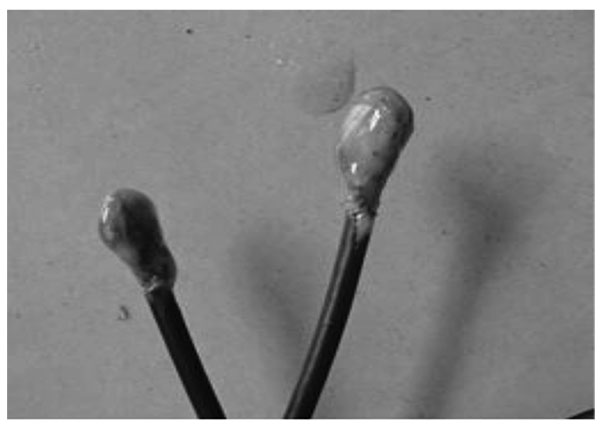
The piezoelectric sensors in this paper were made of PZT-5 piezoelectric ceramics. First, the opposite electrodes of the piezoelectric ceramic element were connected with coaxial cable by conductive silver paint. Then, the piezoelectric was packaged with epoxy. The piezoelectric sensors were shown in Fig. (1). Before the piezoelectric sensors were embedded into concrete, they should be calibrated. In the calibration, the sensor was embedded into a concrete block of 100×100×100 mm, the concrete specimen was shown in Fig. (2).
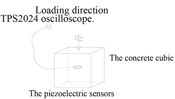
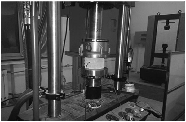
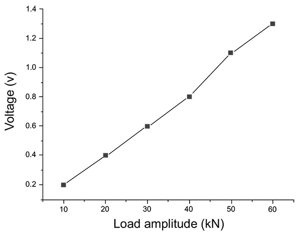
As shown in Fig. (3), the concrete block was subjected to two kinds of cyclic loading (by MTS-250 loading machine). When sine load amplitude (equilibrium of 50 kN, amplitude of 20 kN) remained unchanged, the loading frequency varied from 1 Hz to 35 Hz; When sine load frequency remained unchanged (load frequency of 10 Hz, equilibrium value of 35 kN), the load amplitude varied from 5k N to 25 kN. In this test, data was acquired by TPS2024 oscilloscope.
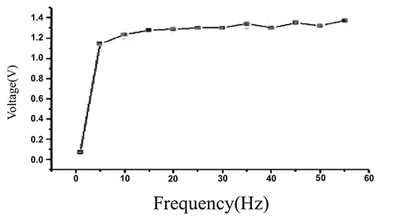
The test results of sensors were shown in Fig. (4) and Fig. (5). In Fig. (4), when sine load amplitude remained unchanged, voltage raised in the range of 1 Hz to 10 Hz sharply and changed slightly in the range of 10 Hz to 35 Hz. This showed that the embedded piezoelectric sensors had a sensitive frequency response. In Fig. (5), when sine load frequency (10 Hz) was unchanged, the voltage changed linearly with the amplitude of load. It showed that the embedded piezoelectric sensors had a good linear output.
3. DYNAMIC TEST OF CANTILEVER BEAM
3.1. Cantilever Beam Model
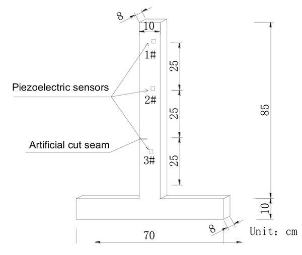
The reinforcing steel bar with diameter of 8 mm was embedded in concrete. In the concrete cantilever beam, three embedded piezoelectric sensors were used. The cantilever beam model was shown in Fig. (6). Before the artificial damage, the natural vibration frequency of the cantilever beam was about 27 Hz.
3.2. Experiment procedure
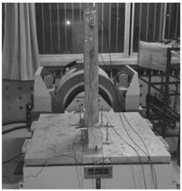
The transient sine load applied to the concrete cantilever beam was provided by horizontal vibration system. The horizontal vibration system (SC-1010 of Suzhou test instrument) was shown in Fig. (7). In experiment, there were two kinds of loading conditions:
Condition 1: when sine load displacement (3 mm) was unchanged, the load frequency varied from 5 Hz to 25 Hz;
Condition 2: when sine load frequency (15 Hz) was unchanged, the loading displacement varied from 1 mm to 7 mm.
In the test, the piezoelectric data was acquired by oscilloscope (TPS2024).
3.3. Test Results and Analysis
3.3.1. The Transient Sine Load Test
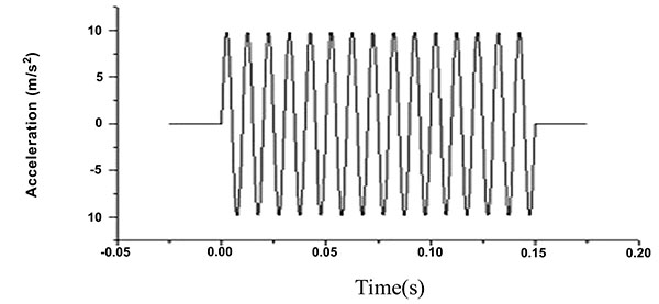
The transient sine load excitation signal was shown in Fig. (8). The output signal of 1# embedded piezoelectric sensor in cantilever beam test was shown in Fig. (9).
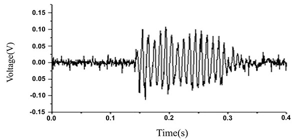
The transient sine load excitation signal was handled with Fast Fourier Transformation, shown in Fig. (10). The output signal of 1# embedded piezoelectric sensor with Fast Fourier Transformation was shown Fig. (11).
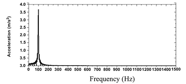
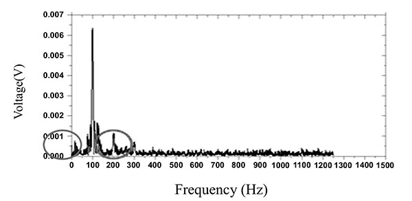
Form the values, it can be seen that the transient sine load system excitation signal and output signal of the 1# embedded piezoelectric sensor had the same time interval of 0.15s with the same dominant frequency of 100 Hz. In other words, the output signal of the embedded piezoelectric sensor was basically consistent with the transient excitation signal of SC-1010 system. In addition, in Fig. (11), the output model of 1# embedded piezoelectric sensor was only affected by the instrument noise in the range of 200 Hz to 300 Hz, but the output noise value was small. It proved that the embedded piezoelectric sensor had good noise immunity.
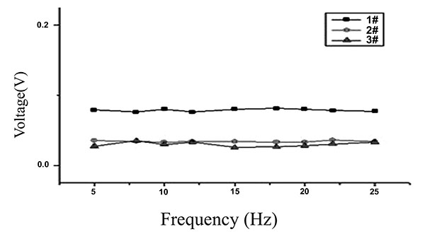
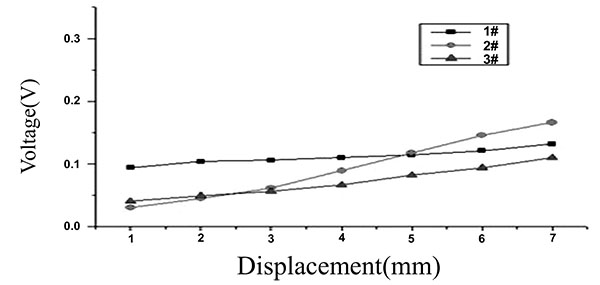
3.4. Sine Loading Test of Cantilever Beam Before Damage
The test data of the concrete cantilever beam in condition 1 before the cantilever beam damaged was shown in Fig. (12). The test data of condition 2 was shown in Fig. (13). When loading displacement of the horizontal vibration was constant, the structural internal force was invariant, too. In Fig. (12), it can be seen that the signal voltage of the embedded piezoelectric sensors changed little with the increasing of the load frequency. It proved that the piezoelectric sensor had good broadband response. Seen from Fig. (13), when the load frequency was constant, the output amplitude of the embedded piezoelectric sensor increased linearly with the increase of the load. It showed that the piezoelectric sensors had a go
3.5. Sine Loading Test of Cantilever Beam After Damage
In order to simulate the damage, the depth of artificial cut seam was 3 cm in concrete cantilever beam. When the concrete cantilever beam was damaged, the test data of Condition 1 was shown in Declared and the test data of Condition 2 was shown in Fig. (14).
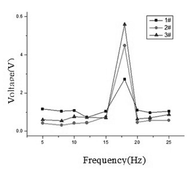
Comparing values of Fig. (12) and Declared, the maximum wave peak appeared at the frequency of 18 Hz. It indicated that the natural frequency of the structure with damage was in the range of 18 Hz to 27 Hz.
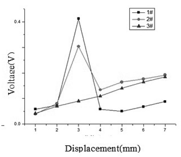
Comparing values of Fig. (15) and Fig. (13), because of the change of the stiffness in the structure, the deformation of structure was changed from the elastic stage to the elastic-plastic stage. And there was a peak value of the voltage when the loading displacement was 3 mm. When the structure was damaged, the natural vibration frequency changes of the structure could be monitored by measuring the structural dynamic stress response with the piezoelectric materials.
4. DYNAMIC TEST OF CONCRETE FRAME
4.1. Concrete Frame Model
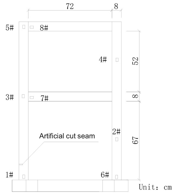
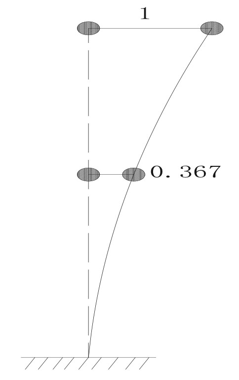
Eight piezoelectric sensors were embedded in the concrete frame model. The concrete frame model was shown in Fig. (16). It could be calculated that the first-order natural vibration frequency of the concrete frame model was about 48 Hz. The first-order vibration schematic diagram of the concrete frame model was shown in Fig. (17).
4.2. Test Procedure
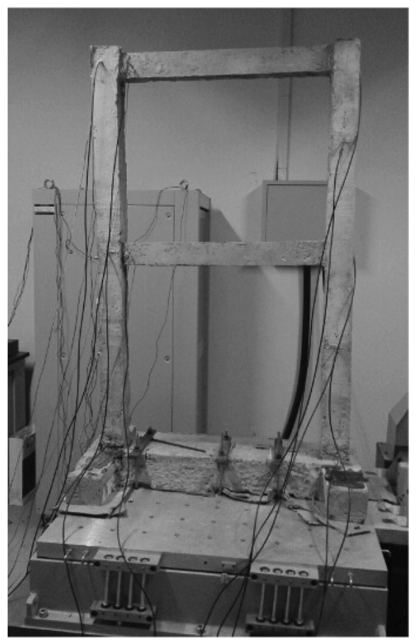
The procedure of dynamic test of concrete frame was similar to the sine load test of concrete cantilever beam. The concrete frame was shown in Fig. (18).
4.3. Test Results and Analysis
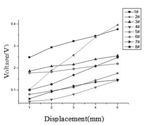
The test data of Condition 1 for the concrete frame after damaged was shown in Fig. (19). The test data of Condition 2 was shown in Fig. (20).
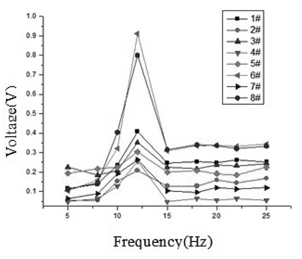
From the Fig. (19), in the range of 5 Hz to10 Hz, the output voltage of the piezoelectric sensors increased slightly with the increasing of the loading frequency. In the range of 15 Hz to 20 Hz, the voltage amplitude of the piezoelectric output was no longer changed and kept constant with the increase of the loading frequency. In addition, when the structure was damaged, the first-order natural vibration frequency of the structure changed from 48 Hz to 12 Hz. Seen from Fig. (20), when the load frequency was constant, the output voltage of the piezoelectric output was almost linear with the increase of the load.
CONCLUSION
Based on the dynamic tests of concrete structures above, it can be concluded that:- The embedded piezoelectric sensors have good noise immunity;
- The piezoelectric smart materials have a good linear output and a wide frequency response for the structural dynamic strain monitoring;
- By the monitoring of the structural dynamic strain response, the piezoelectric material can be used to monitor the changes of the structural natural frequency when the structure is damaged or the structural stiffness changes.
Based on the summary above, it can be concluded that the piezoelectric materials have great prospect in the application for structural dynamic response monitoring.
CONSENT FOR PUBLICATION
Not applicable.
CONFLICT OF INTEREST
The authors confirm that this article content has no conflict of interest.
ACKNOWLEDGEMENTS
Declared none.

