All published articles of this journal are available on ScienceDirect.
Hydrodynamic Study of the Flows Caused by Dam Break around Downstream Obstacles
Abstract
Introduction:
Studying dam break and the resultant flood routing along with identifying critical areas at the dam downstream are of great importance in safety management of the dam break issues. To reduce the risk of the dam break, an accurate estimation of the effective parameters on the energy dissipation due to the collapse of dams and the flood routing around the downstream natural and artificial obstacles is necessary.
Methods:
In this research, effects of downstream obstacles (e.g. bridge piers) caused by dam break were investigated on different flood patterns in the flow characteristics. Accordingly, two different geometries of the long and wide reservoirs were considered in the experimental tests and 3D numerical simulations.
Results and Conclusion:
The results indicated the formation of different flow patterns at downstream of the long and wide reservoirs depends on the reservoir geometry. Due to the alignment of the channel and the reservoir in the long reservoir case, the dominant flow was one-dimensional up to the collision with the pier. Therefore, the one-dimensional solutions, including Ritter analytical solution could be applied in this range. After the flow passes through the pier, due to the formation of the wake vortices, the one-dimensional state was no longer valid. This caused turbulence at the surface of the water, which continued to the end of the channel. In the wide reservoir, from the beginning of the flow entry into the channel until its moment of collision with the pier, as well as passing through it, the flow lost its one-dimensional state. In such a case, the use of 3D models was necessary to achieve the appropriate accuracy.
1. INTRODUCTION
The importance of the failure problem is because the risks of the incidents are directly associated with the human societies; therefore, floods with long return periods are usually considered for dam constructions. The prediction of hazardous conditions in times of crisis will provide the necessary measures to prevent increased risk levels. In this regard, designers of the hydraulic structures such as dams that deal with the security of human societies, attempt to model critical situations experimentally or through numerical simulation to obtain more information to deal with the critical situation. Due to the high cost of modeling complex phenomena experimentally, today numerical methods are highly considered. Therefore, in recent years, numerous numerical models have been developed and widely used to investigate this phenomenon. The unsteady flow caused by dam break is described by Navier-Stokes equations, the analytical solution of which is not available except in very specific conditions. Therefore, numerous attempts have been made to develop numerical methods that resulted in three numerical methods of finite difference, finite volume, and finite element. In recent years, the finite volume method has been considered by researchers as a powerful means to investigate this phenomenon. Descriptive studies on the fundamental concepts of dam break date back to Ritter's efforts [1]. Ritter provided an analytical solution to the hydrodynamic problems of sudden dam break in a horizontal and non-frictional rectangular channel. Glaister [2] first applied the Roe’s flux difference splitting (FDS) for these equations and even developed an approximate solution for Riemann problem for shallow water equations. Zhao et al. [3] presented a two-dimensional model of finite volume for an unstructured network based on the approximate solution of the Riemann problem using the Osher approach and while solving problems such as dam break, they provided appropriate answers in case of Kissimmee River in Florida. Nujic [4] proposed two simplified but high-order accuracy based on the methods of calculating Lax Friedrichs Flux and Osher and solved the flow on complex geometry with proper precision using some modifications. Jha et al. [5] with an emphasis on the need to satisfy the entropy equation condition in the numerical analysis of equations showed that Roe’s first-order method is more suitable than the extended second-order versions. Fraccarollo and Toro [6] used one of Godunov methods along with weight-averaged flux. The physical model was constructed by the authors to evaluate the validity of this numerical simulation. In this study, the applied numerical simulation was based on the use of shallow-water equations. In addition, the difference between the numerical results and the experimental data near the gate has been due to the presence of gradients in the free surface. Tseng et al. [7] carried out numerical and experimental investigations on the dam break. In Tesung et al. [7], the MacCormack method is used in combination with Roe’s first-order, TVD and ENO methods. The reported results suggest the identical capability of these methods in the face of the dam break problem; however, the Roe method is less satisfactory. Soares and Zech [8] examined the dam break problem experimentally and numerically at a 90-degree bend. Based on the results of this research, it is believed that the application of numerical simulation of dam failure in a one-dimensional case has limitations. Mahapatra and Chaudhry [9] studied the effect of non-hydrostatic pressure distribution of the flow obtained by the dam break using the one-dimensional analysis of the Boussinesq equation and first-order finite-difference. Abdolmaleki et al. [10] used a direct Navier- Stokes Equations’ solver to simulate free water surface in the dam break problem. They simulated the free surface water using the Fluent software and the VOF method. The results indicate the proper accuracy of the solver for dam break simulation. In another study, Demaio et al. [11] used the Fluent 3D software to simulate the wave formation after the dam break. The authors modeled the wave formed in the early moments after the dam break and compared the results with existing experimental results of the Fluent software. This comparison showed the appropriate accuracy of the data obtained by the Fluent compared to the experimental values. Soares and Zech [12] studied the flow pattern around an isolated obstacle against the flow due to dam break experimentally. In this study, changes in water level and velocity were measured using the resistive gauges and ADV respectively. The surface velocity was obtained by the digital imaging method installed at the top of the channel. In addition, Soares [13] investigated the wave propagation caused by dam break around a triangular obstacle in the bed. In this study, the flow pattern was investigated around such an obstacle. Aureli et al. [14] studied the water level variations using image processing and compared them with the results of a two-dimensional numerical model and showed that there was a relatively suitable correlation between experimental data and numerical model. Soares-Frazão and Zech [15] conducted an experimental and numerical study on flow characteristics caused by the dam break in the idealized city in the downstream gate. In this research, two series of experiments were done on the flow caused by the dam break. In the first series, the idealized streets were placed along the flow path. In the second series, the effect of street orientation was studied by rotating the city. Moreover, the finite volume numerical model based on shallow water equations with unstructured meshes was presented and the accuracy of this model was investigated in different modes. Ozmen and Kocaman [16] performed an experimental and numerical study on the flow caused by the dam break in the channel with dry bed with a sudden narrowness at a section. The results showed that a sudden narrowness caused the formation of a negative bore in the canal. Feizi et al. [17] used the physical modeling to interpret and understand the effect of the reservoir geometry on the flow characteristics, especially the outlet hydrograph of the physical modeling. They concluded that among the studied reservoirs the highest water level, velocity and output discharge in dry and wet bet conditions was associated with the wide reservoir and a faster attenuation in the maximum level occurred in this reservoir. Aureli et al. [18] studied the ability of three different models in estimating the effective load applied to the obstacles located at the downstream of the dams due to flows caused by the dam break. The models of this study included 2D depth-averaged, 3D Eulerian two-phase and 3D Smoothed Particle Hydrodynamics (SPH) models. The results indicated that 3D models are more capable of obtaining the hydrodynamic features of the flow applied to the obstacles but the 2D models developed based on shallow water equations cannot provide the load variations applied to the obstacle and their maximum value fully and precisely. Of course, it is noted that the 2D model error in estimating the maximum applied load to the obstacle is about 10% different with the experimental value; therefore, 2D models could be used in applied projects. Costabile et al. [19] studied how the flood wave propagates in rivers with or without pier using one-dimensional and two-dimensional numerical models and analyzed the effect of the presence or absence of such piers on the flood flow. Studies conducted in this research showed that since the river sections are almost rectangular, the one-dimensional model has logical solutions, nevertheless, the analysis of the results would further clarify the 2D characteristics of the flow, which may be effective in risk assessment and should be considered. Jian et al. [20] performed the hydrodynamic simulation of the flow caused by dam break near the moving structures. In this study, the weakly compressible Smoothed Particle Hydrodynamics (WCSPH) and incompressible Smoothed Particle Hydrodynamics (ISPH) models were used to investigate the effect of fixed and moving obstacles on the flow caused by the dam break. The results of this study showed that the ISPH has a better performance than WCSPH model in terms of stable motion of particles and the simulation time. Hooshyaripor and Tahershamsi [21] addressed the effects of the reservoir wall slope in the flows caused by the dam break on the resultant wave experimentally. The results of their research indicated that the reservoir with a 30-degree gradient caused the highest flow rate in the path. Javadian et al. [22] studied the experimental model of the dam break phenomenon and compared its results with the analytical solution of Saint Venant's equations. The results showed that the experimental and theoretical responses were appropriately close; however, due to the assumptions considered on the characteristic method for the analysis of the Saint Venant's equations, the experimental and theoretical methods had inherent differences. The effects of reservoir length and volume on the flow profile due to the dam break are discussed by Hooshyaripor et al. [23]. Moradi Mofrad et al. [24] conducted the numerical investigation of the turbulent flow caused by the dam break around the trapezoidal barrier located at the gate downstream. In this research, the finite volume method and OpenFOAM software were used. The experimental results of other researchers were used to evaluate their models. Results indicated the accuracy of model in simulating the flow due to dam break around the barrier compared to the experimental results.
Despite the considerable amount of researches in this area, there is still lack of information about the flow characteristic around obstacles on different flow patterns caused by dam break phenomena. Therefor in this research, in order to cover a wide range of uncertainties, two different geometries of long and wide reservoirs were considered in simulations. To investigate the effect of cylindrical pier on flow characteristics (such as changes in water level and velocity around it), a series of 3D numerical simulations together with the experimental tests were carried out. Based on the obtained results from tests and numerical simulations, the flow patterns caused by the dam break on the reservoir downstream, also the hydrodynamic changes around the pier were examined in details.
2. MATERIALS AND METHODS
2.1. The Governing Hydrodynamic Equations
The equations governing an incompressible and viscous fluid flow are expressed by mass continuity equations (Eq. 1) and momentum equations (Eq. 2 to 4) known as Navier-Stokes equations. In fact, these equations represent mass and momentum stability mathematically. Since this type of flow is turbulent, to investigate the flow field in the dam break, the Navier-Stokes equations should be solved as time-dependent and then the turbulence terms should be included. The Navier-Stokes equation for turbulent flows with an incompressible fluid in x, y, and z direction are as follows [25]:
 |
(1) |
 |
(2) |
 |
(3) |
 |
(4) |
 ,
,  and
and  are average velocity values in three directions x, y and z, and
  ,
,  and
and  indicate the Coriolis forces in three coordinate directions. The terms 1, 2, and 3 in Eq. (2), (3) and (4) in averaged time-dependent Navier-Stokes are called Reynolds stresses.
The main capabilities of the 3D Fluent software for hydraulic analyses include modeling free-surface flows and applying the finite volume method to solve Reynolds averaged Navier-Stokes' equations. In this software, the free surface is modeled by the VOF technique. In the VOF method, the region to be modeled is divided into smaller elements or control volumes. For fluid-containing elements, the numerical values are maintained for each of the flow variables such as pressure, temperature, and velocity within them. Since the volume fraction F expresses the amount of fluid in each cell, it takes a value between zero and one. The volume fraction is equal to one and zero in the internal and external and gas zones respectively. The free surface is where the volume fraction varies between zero and one. In the present paper, Fluent software [26], which operates in a finite volume method, is used to solve equations.
2.2. Geometry of the Model
In this paper, in order to simulate the obstacle at the gate downstream and the numerical modeling, a new experimental model (including the pier at the gate downstream) was constructed in the hydraulic laboratory of Amirkabir University. The pier was cylindrical with a diameter of 0.04m, which was made of Plexiglas material and was located at a distance of 1.08 m from the center of the gate. The conditions prevailing in the current experiments, including how to create a dam break mechanism, the devices used to measure water level variations and velocity were the same as the experiments conducted by Feizi et al. [17]. In all experiments, the initial reservoir water level was 0.4 m and the gate downstream bed was dry. In this paper, to study the effect of cylindrical pier on different flood patterns due to dam break, reservoirs with long and wide geometries were considered in the experimental tests and numerical simulations. Fig. (1) shows the schematic of the reservoirs plan, flume and the obstacle (pier) location as well as the points determined to check the variations in water level and velocity. In order to create equal initial conditions in simulations for both models, the volume of water in both reservoirs is considered the same. Table 1 shows the coordinates of the measurement points. The origin of the coordinates is located at the center of the gate so that it is along the positive direction of x-axis along the flow.
2.3. Boundary Conditions and Effective Factors Applied in Modeling
The initial and boundary conditions used in the numerical analyses were defined as follows:
- Outlet (flume end boundary) was a type of pressure-outlet boundary condition;
- The free surface of water was a type of pressure-inlet boundary condition;
- The walls and bottom of the reservoir were of the Wall (no slip) conditions;
- The fluid inside the reservoir was defined as air and water;
- At the initial moment, all velocities in the reservoir and channel were zero.
| Gauge | x(m) | y(m) |
|---|---|---|
| G1 | 0.83 | 0.1175 |
| G2 | 0.83 | -0.1175 |
| G3 | 0.98 | 0 |
| G4 | 1.08 | 0.1175 |
| G5 | 1.08 | -0.1175 |
| G6 | 1.33 | 0 |
| G7 | 1.48 | 0 |
| G8 | 1.58 | 0 |
| G9 | -0.1 | 0 |
| G10 | -0.5 | 0 |
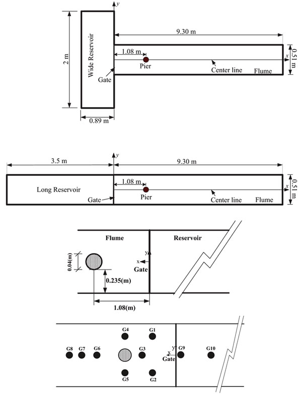
Table 2 provides a summary of the settings and algorithms used in the simulations of this paper. The volume of fluid (VOF) model has been used to determine the boundary between the air and water in flow simulation in the dam reservoir. This model was designed to determine the common boundary of two non-mixing fluids and was based on the theory of multiphase flow. In this paper, In order to check the model sensitivity to the mesh-size, meshes of 0.01, 0.03, 0.05, and 0.1 meters were tested. Based on the results, the meshes with the size of 0.01m at x, y, and z were selected as the appropriate mesh for performing subsequent simulations. In addition, after analyzing the sensitivity of the numerical model compared to other turbulence models, it was decided to use the RNG model for modeling and investigating turbulence. To solve the flow equations simultaneously, momentum and continuity equations and the velocity-pressure coupler algorithms are needed. SIMPLE, SIMPLEC and PISO algorithms are the three available algorithms in Fluent and used in the simulations. After analyzing the sensitivity of the numerical model, it is found that the PISO algorithm allows larger time steps and at the same time maintains the under-relaxation factors for pressure and momentum close to one. Hence, this method was applied in the coupling analysis.
| Input | Description | Category |
|---|---|---|
| Default values | Pressure Based, Implicit, Unsteady, First Order |
Numerical Solver |
| Discritization Scheme: Geo Reconstruction | VOF, Implicit Scheme, Body Force Treatment |
Multiphase Model |
| PRESTO | RNG, Standard Wall Function | Turbulence Model |
| First Order Upwind | Pressure | Discritization Scheme |
| First Order Upwind | Momentum | |
| First Order Upwind | Turbulent Viscosity | |
| First Order Upwind | Turbulent Dissipation rate | |
| Skewness-Neighbor Coupling | PISO | Pressure-Velocity Coupling |
3. RESULTS AND DISCUSSIONS
3.1. Analyzing Water Level Variations
Based on Analytical Ritter Solution, the water level profile variations are calculated by Eq 5:
 |
(5) |
Where X and Z are the spatial dimensionless coordinates defined as X = x/h0 and Z = h/h0 . Where, x is the distance between a point in the flume and the beginning of the flume (gate), h0 is the initial level of water in the reservoir and h is the water level variations. The time dimensionless parameter is also T=t (g/h0 )0.5 that t is the time and g is the acceleration of gravity.
Fig. (2) shows a comparison between the three-dimensional numerical model for both long and wide reservoirs, Ritter analytical solution and experimental data for variations in water level at the points G1, G3, G4, G6, G7 and G9. In these figures, the Z dimensionless values vs. T are plotted.
Table 3 presents the average difference between the experimental tests, 3D numerical model and Ritter's analytical solution for the long reservoir. Accordingly, within the range of T=0 to T=20, the water level from the experimental test is comparable well with Ritter's analytical solution. After this range, the water level variations have a decreasing trend due to the reservoir drainage while this trend is not observed in Ritter's analytical solution because the reservoir is assumed as infinite. Comparison of water level variations between the three-dimensional numerical model and the Ritter's analytical solution at the points between the dam (gate) and the pier i.e. points G1 and G3 in a downstream channel connected to long reservoir shows a small difference with the experimental data (about 8-12%). The reason for such low difference is that the super-critical flow created by the dam break in this area is parallel to the reservoir flow and there is no change in water path and complicated flow. Thus, the flow is one-dimensional and the three-dimensional numerical model and the analytical solution have close accuracies and are in appropriate agreement with experimental values.
| – | 3D Numerical Model | Ritter’s Solution |
|---|---|---|
| Gauge | Average Difference (%) | Average Difference (%) |
| G1 | 12 | 14 |
| G3 | 8 | 12 |
| G6 | 18 | 22 |
| G7 | 24 | 40 |
| G9 | 2 | 7 |
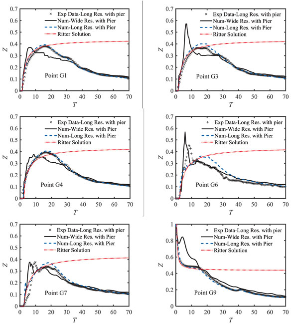
The numerical results at points G1 and G3 in the downstream channel of the wide reservoir indicate that the water level reaches its maximum value faster than similar points of the long reservoir. The reason for the maximum water level and faster attenuation of these points in the wide reservoir compared to the long reservoir is the formation of cross-waves in the wide reservoir's downstream, which is directly related to the reservoir geometry. However, such flow was not observed in the long reservoir and this is mainly due to the alignment of the reservoir and the downstream channel. Besides, fluctuations at the downstream water level are due to the reservoir geometry. After a sudden opening of the gate, surges are created and due to the short reservoir length, these waves can go forward and backward across the reservoir. Nevertheless, these waves are depreciated throughout the reservoir. The average difference between the numerical values obtained between the long and wide reservoirs at G1 and G3 points is 11 and 14%, respectively. Until 2 seconds after opening of the gate, the water level of the wide reservoir is higher than the long reservoir. Between 2 and 6 seconds, due to a faster attenuation of water level in the wide reservoir, the water level in the long reservoir is higher and after six seconds, the two reservoirs reach the same level. Comparison of water level variations between the three-dimensional numerical model and Ritter's analytical solution at the points between the dam (gate) and the pier i.e. points G6 and G7 for long reservoir indicate a significant difference between the values of the 3D numerical and experimental model due to the formation of the wake vortices. The range of differences is about 18 to 24% (Table 3). A similar trend takes place in the wide reservoir at the G6 and G7 points, except that due to the simultaneous effect of the cross-waves and wake vortices in the wide reservoir downstream channel, the intensity of the water level variations in wide reservoir is higher at the initial moments after the dam break. Moreover, at the inside points of the long reservoir (point G9) the water level difference between the numerical model and experimental data are not significant, which indicates high accuracy of numerical simulation at these points. The reason is that the flow conditions in the inside points of the reservoir are sub-critical causing one-dimensional flow to dominate those points. In the wide reservoir, the water level has a sharp drop in the inside point of reservoir right after opening the gate. After this sharp drop, the water level water level immediately increases and reaches its maximum and then decreases again. The reason for the increase in water level after a sudden drop is that the negative wave entering the wide reservoir reflects after colliding with the lateral walls of the reservoir and moves towards the gate. This reflected flow is fast and intense at the initial moments after opening the gate and collides at the G2 point, which increases in the water level at this point. Over time, the intensity of the reflected flow from the lateral walls reduces and causes small fluctuations in water level. The water level at the G9 point in a wide reservoir is 21% higher than the same point in the long reservoir on average.
3.2. Analysis of Velocity Profile Variations
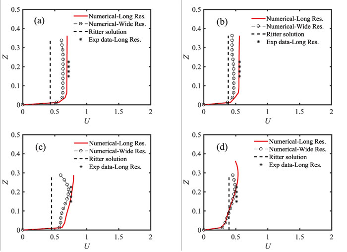
Fig. (3) shows the distribution of the velocity obtained by 3D numerical model and the Ritter’s analytical solution at the flow depth in vs. the experimental values for long and wide reservoirs. The relative difference between each method with experimental data for long reservoir is presented in Table 4. The curves in Fig. (3) are mapped as dimensionless at points G2 and G6. In these diagrams, the dimensionless parameters U and Z are defined as Z = h / h0 , where u is the flow velocity in the direction x, h0 is the initial level of water in the reservoir, h is the depth of flow and g is the acceleration of gravity. Eq. (6) is also used to calculate U by Ritter's analytical solution:
| – | t=2s | t=4s | ||
|---|---|---|---|---|
| 3D numerical model | Ritter’s solution | 3D numerical model | Ritter’s solution | |
| Gauge | Average Difference (%) | Average Difference (%) | Average Difference (%) | Average Difference (%) |
| G2 | 8 | 30 | 6 | 4 |
| G6 | 5 | 31 | 7 | 23 |
 |
(6) |
Where X, T and U are the dimensionless spatial, time and velocity coordinates defined as X = x / h0 , T = t (g/h0 ) 0.5 and. Where x is the distance between the point in the flume from the beginning of the flume (gate), u is the flow velocity in the x-direction, t denotes time and g is the acceleration of gravity.
Fig. (3) shows that in Fluent model, the velocity variations start from zero on the bed and trend to a certain amount away from the wall, while the velocity value is assumed to be uniform in depth in Ritter’s analytical solution. According to Table 4, at t = 2s and t = 4s at G2 and G6, the highest and the lowest difference is related to the Ritter’s solution and the 3D numerical model for long reservoir, respectively. The reason for such difference between Ritter’s solution and the experimental data (at time t = 2s, point G2) is that Ritter’s analytical solution is mainly valid for the points located on the central line of the flume, and the G2 point is not on the central line. For point G6, although this point is located on the central line, the flow is no longer one-dimensional due to the formation of wake vortices. Accordingly, since Ritter’s solution is mainly valid in one-dimensional state, the results of this model are different from the experimental values. The difference between Ritter’s analytical solution and the experimental values at t = 4s is less than t = 2s. This is due to the decrease in flow variations confirming the one-dimensional flow state. The velocity distribution from the 3D model at the depth of flow in the channel connected to the wide reservoir shows that at t=2 and 4 seconds after opening the gate, the wide reservoir's velocity at points G2 and G6 is lower than the same values in the long reservoir. This is mainly due to the inflow from the sides to the downstream channel and the creation of cross-waves in the wide reservoir. Moreover, at point G6, due to the interference of the cross-waves and wake vortices, uniform variations in the velocity distribution are reduced and they are accompanied by fluctuations in the flow depth.
3.3. Analysis of Pressure Variations
Fig. (4) shows the pressure variations in the flow depth at the pier as well as point G3 in the channel downstream connected to the long and wide reservoirs at different times. Accordingly, in the long reservoir, the pressure on the pier increases at the initial moments after the dam break until it reaches its maximum value at t = 1s after opening the gate. This increase in pressure happens from the bottom of the channel to a flow depth of 0.1 m and pressure variation decreases after passing this depth. The reason for this pressure change is that at this time, the flow depth at the pier is about 0.1 m, and the horizontal component of the velocity along the flow is large at this time. Therefore, due to the collision of such a high-velocity flow with the pier and velocity conversion to the pressure (creating a stagnation point), it causes maximum pressure to a depth of 0.1 m from the bottom of the channel. Gradually, by decreasing the velocity component, the amount of pressure applied to the pier decreases, so that at t = 10s, the pressure changes occur with the same trend at the point G3 and the pier.
In the wide reservoir, the pressure variations around the pier and point G3 are similar to those in the long reservoir. At point G3, until the first 1.5s after opening the gate, pressure variations in the wide reservoir are greater than the similar value in the long reservoir. However, as illustrated in Fig. (4), this variation is intermittent over the time. In the wide reservoir downstream, the pressure variations created around the pier are greater than or equal to the observed value in the long reservoir.
3.4. Longitudinal Profile Variation of Water Level
Fig. (5) shows the comparison between numerical and experimental results of flood wave expansion at the downstream of long and wide reservoirs in dry bed conditions at t=2 and 4s.
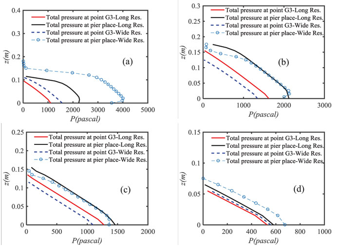
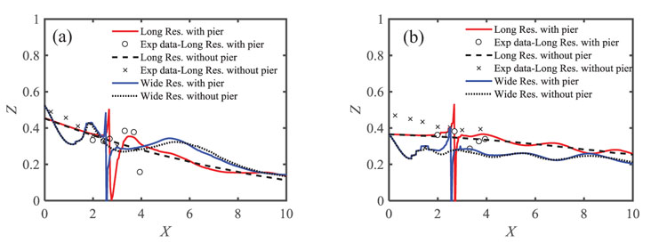
Fig. (5a) shows the longitudinal profile of water level with and without pier at t = 2s for long and wide reservoirs. Accordingly, in the channel connected to the long reservoir and at a distance between the gate and 100cm farther (toward the pier), the water level variations for the pier presence are less than the absence of pier. The reason for this is the effect of the pier on the flow lines and the contraction of the flow in this range. After this distance, the changes in the water level in the model with pier are altered at the gate downstream compared to the model without pier. The sudden increase in water level is also observed within the distance of 100 to 150 cm from the gate. The main reason for sudden increase in water level is the existence of wake vortices at this distance. According to Fig. (5a), at 0.5 m distance from the gate, the water levels profile of the wide reservoir has a sudden drop (for the cases with and without pier) while this water level has increased at a distance of 0.8 m from the gate. After this increase, the water level profile decreases until the flow hits the pier. As discussed above, the reason for this is that the transverse waves are reflected from the channel walls causing the formation of crests and troughs on the water level profile of this reservoir. Similar to the long reservoir, the wake vortices are created behind the pier and the water level increases compared to the absence of pier.
Fig. (5b) shows the longitudinal profile of the water level for the conditions with and without the pier at t=4s for long and wide reservoirs. With respect to the water level, results indicate similar changes for both reservoirs compared to the previous state (t=2s) with the difference that over time the wake vortices rising towards the pier in nearby places and their intensity is reduced.
3.5. Flood Wave Motion
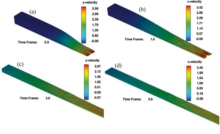
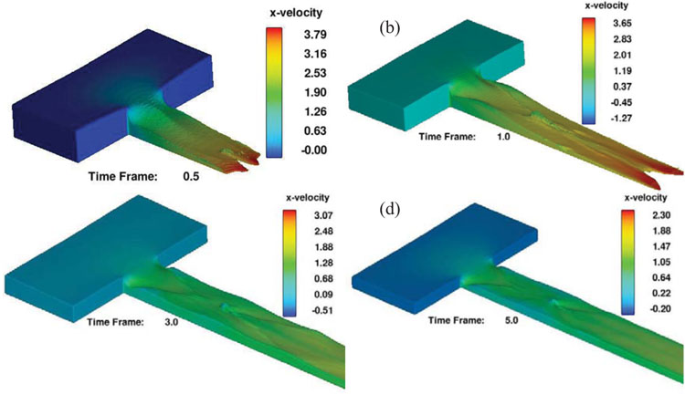
Figs. (6 and 7) illustrate the flood wave motion at different times for the channel connected to the long and wide reservoirs. The backflow of the wave into the long reservoir is clearly visible in Fig. (6). Based on the images, in the first moments after the dam break, the flood wave moves at a high velocity towards the downstream. Since the pier is located in the middle section of the channel connected to the long reservoir, it causes the waves to collide with the side walls and its re-entry into the channel, which results in transverse waves. In addition, because of the presence of pier, the wake vortices are clearly visible behind the pier. Over time, with the reservoir drainage, the intensity of the outflow is reduced and the wake vortices lose their effect. According to the images, the maximum longitudinal component of velocity decreases, which is due to the drainage of the long reservoir and the reduction of the level of water flow on the outlet. Fig. (7) shows that the flood wave motion of the downstream channel connected to wide reservoir is different due to its geometry. Accordingly, in this reservoir, in the initial moments after the dam break, the flood wave moves with higher velocity but with the faster attenuation towards the downstream than the long reservoir. Due to the creation of cross-waves at the reservoir downstream, water level variations are fluctuating and these fluctuations continue throughout the channel. Due to the presence of the pier in the middle of the channel connected to the wide reservoir, the wake vortices behind the pier collide with cross-waves and make the flow more turbulent in this zone.
CONCLUSION
In this research to investigate the effect of cylindrical piers on different flow patterns, the experimental study and 3D numerical simulation are conducted. A summary of results indicates that the existence of the pier in both long and wide reservoir conditions has no significant effect on water level variations inside the reservoir points and Ritter analytical solution values and 3D modeling results have no significant difference with the experimental results. The reason for this is the prevalence of sub-critical flow regime inside the reservoir. Besides, the reservoir shape has a significant impact on different flow patterns created at the gate downstream. Due to the alignment of the channel and the reservoir in the long reservoir, the dominant flow until its collision with the pier is 1D. Thus, one-dimensional solutions (including Ritter analytical solution) and 3D modeling at points G1 and G3 show no significant difference and fit well with the experimental data. After the passage of the flow through the pier, (points G6 to G8) due to the formation of the wake vortices, the flow loses the one-dimensional state and causes turbulence on the water surface. In this range, the Ritter analytical solution is far from the experimental data showing very low accuracy. Instead, the 3D numerical model provides acceptable results with a high accuracy in this range. In the wide reservoir, the cross-waves are formed at the reservoir downstream due to the effect of the reservoir geometry. From the beginning of the flow entry into the channel until its moment of collision with the pier, as well as passing through it, the flow loses its one-dimensional state. After the passage of flow through the pier, the severity of turbulence increases due to simultaneousness of the cross-waves and wake vortices. Hence, the Ritter analytical solution does not provide adequate answers in the entire channel while the three-dimensional numerical model has the appropriate accuracy. The velocity distribution obtained from the three-dimensional numerical model at the flow depth indicates that the velocity of points between the gate and pier is smaller in the channel connected to the wide reservoir than the ones for the long reservoir. This is mainly because of the entry of the flow from the sides into the downstream channel and the creation of cross-waves. After the flow passes through the pier, the velocity distribution of the points located in this zone in the channel connected to the wide reservoir is equal to or less than the long reservoir. However, because of the confrontation between the cross-waves and wake vortices, the in-depth velocity variations are not uniform and accompanied by fluctuations in the flow depth.
CONSENT FOR PUBLICATION
Not applicable.
CONFLICT OF INTEREST
The authors declare no conflict of interest, financial or otherwise.
ACKNOWLEDGEMENTS
Declared none.


