All published articles of this journal are available on ScienceDirect.
Spatial Correlation of Cone Tip Resistance for Soil in Nasiriyah
Abstract
Background:
Quantification of soil property spatial variations is an important step in any reliability-based design. Little stochastic parameter information about the soil in Nasiriyah, which is in southern Iraq, is available.
Methods:
In this paper, the Scale Of Fluctuation (SOF) for the site soil is examined, which is suggested for construction of the refinery fuel station project as no random parametric quantity has been studied in this region. A Cone Penetration Test (CPT) was performed as part of the site investigation to a depth of 20 m in the vertical direction, and 24 CPTs were analyzed within the site. The spatial correlation was computed using four methods, including Single Exponent (SNE), Square Exponent (SQE), Cosine Exponent (CSE) and Second-Order Markov (SOM). Identification of the soil type depended on the most recent classification chart, which is based on CPT results. The spatial correlation was evaluated for the vertical direction considering the cone tip resistance (qc) component. Three trend functions were applied to all CPT soundings, including linear, quadratic and cubic polynomials, which were utilized to transform the non-stationary data to stationary data. Three modes of soil were employed, including the eight-meter soil layer, a twelve-meter soil layer and the entire twenty meters of soil, which includes both layers.
Results and Discussion:
The mean values of SOF were 0.54 m, 0.53 m, and 1.73 m for soil layers 8 m, 12 m, and 20 m, respectively. The high value of the last mean is attributed to the 20 m of stratification in the ground. This study also indicates that the SOF decreases as the polynomial degree increases, which is due to enhanced fitting. The coefficient of variation (COV) for the SOF shows little variability for most of the studied soil cases.
1. INTRODUCTION
Engineering characteristics of soil show the spatial correlation nature, which is important because the geotechnical problems currently require full reliability-based design [1]. The soil at a construction site must be statistically well investigated so that the geotechnical project is correctly designed using a reliability-based design method. Different soil properties have been studied spatially based on the CPT, such as undrained cohesion [2] and liquefaction potential of soil [3-5]. Field tests have also been successfully used for analyzing soil variabilities including the vane shear test [6], Standard Penetration Test (SPT) [7] and CPT [8, 9]. Researchers have dealt with different soils such as weathered soil [10] and soft soil [9]. Most recent design codes require that the variability parameter is included in the reliability-based design. Many studies demonstrated considerable SOF effects on the geotechnical design problem [11-13]. The spatial correlation is relevant to the inherent soil property, which is an uncertainty that cannot be avoided. This uncertainty is a primary uncertainty type, where the primary sources of uncertainty can be classified into three categories: inherent soil variability, measurement errors and transformation uncertainty [14]. The inherent soil variability, which mostly results from natural geologic developments, can be modeled as a random field with the scale of fluctuation.
Many researchers analyzed the variation in soil parameters with depth as a time series and changed the time by the depth. Vanmarcke [15] applied the random field theory to analyze the variability in soil parameters. To describe the soil stochastic parameters, three parameters have to be quantified: The mean (u), the variance or COV and the SOF [16]. Computation of the mean value and the COV for the soil parameters are relatively simple compared to the computation of the SOF. SOF can be estimated by numerous methods such as the autocorrelation function based on random field and time series theory, semivariogram based on geostatistics, local average subdivision area, moment method and maximum likelihood method [6, 17-23]. The simplest and most widely used method used to estimate SOF is by best fitting the theoretical correlation model to the experimental correlation function. Vanmarcke [24] proposed an alternative method, based on the concept of the variance function [22, 25, 26]. Some studies compared the semivariogram and autocorrelation [27], while others compared the vertical and horizontal SOF [28].
The SOF for qc is defined as a distance within which values of qc are significantly correlated [15, 19]. The SOF is a suitable scale for describing the spatial variability of a soil property in a random field. Several types of research have been performed to indicate the SOF for qc within the soil. For clean sand, the SOF is 3 m; for Mexico clay, it is 1 m [29], and for silty clay, the SOF is also 1 m [30, 31]. Phoon and Kulhawy [32] observed a SOF range of 0.1-2.2 m for qc. For sand and clay, the SOF was between 0.13 m and 1.11 m [33]. For the cohesive Auckland residual soil, SOF ranged between 0.2 m and 0.5 m [34] and 0.15 m and 2 m for stiff clay [16].
Based on previous studies, the SOF values are different even for the same soil. The SOF value obtained theoretically is different from the actual value. There are several factors affecting the SOF such as the sample interval, the size of the sample, location of the site, CPT data, trend function, and problem scale [1, 30, 33, 35]. Selecting a conservative value for SOF for use in random field applications based on previous studies is difficult because of the high range of SOFs available [36]. Therefore, it is necessary to analyze the data for each specific site and compute the SOF values to obtain an accurate result. Quantifying the SOF for the soil at the site in Nasiriyah is crucial because there are no available studies on the soil and several previously mentioned factors may affect the values. The CPT has the advantage of providing near continuous data-based strength [37], which is used in many countries and has a high theoretical background. CPT can be used even in low-risk projects; however, in some countries and because it is expensive [38], CPT is used only in large projects such as in Iraq. The results obtained through CPT can be analyzed and used to quantify the SOF for where very few studies on the stochastic nature of soil are available.
In this paper, the SOF of the qc for soil in Nasiriyah is calculated based on data obtained through performing twenty-four CPT soundings as part of a soil investigation for construction of a refinery station. The vertical SOF is calculated based on four types of autocorrelation functions for all CPT soundings. These types are single exponential, cosine exponential, square exponential, and second-order Markov. Trend functions are also suggested to be linear, quadratic and cubic polynomial to remove the non-stationary from the data and to quantify their effects on the SOF. Comparisons between the SOF obtained through different methods as well as a comparison with the values reported in the literature are presented. Since a large range of horizontal SOF values is available in the literature, which ranges from 0.184 to 80 m [39] or from 0.14 to around 600 m [13], it is challenging to precisely quantify the horizontal SOF since the CPT sounding values are not to close each other. This study focuses only on the vertical SOF and the investigation of horizontal SOF will be addressed in a future study. No geotechnical applications are presented in this study based on the reliability design. The focus of this study is on quantifying parameters utilized in random field applications. The study addresses the site in a city with no previous statistical information available regarding the soil properties of this region. This paper contributes essential information regarding reliability-based design; however, no actual random field application is achieved.
2. STOCHASTIC ANALYSIS
2.1. Spatial Variability of Soil
Spatial variability of soil properties is a term referring to soil properties that are variable from one point to another point, which can be defined as uncertainty that cannot be avoided in design [40]. Since the properties of soils are naturally variable due to the complicated processes of physical, chemical and biological decay, they are considered to be inherently spatially variable soil properties [10]. Two mathematical techniques are used, including geostatics and time series analysis or random field when the time is replaced by distance lag. The data are stationary, and the probabilistic laws are independent of the sample locations. Modeling of the spatial variability of the soil properties implies using several statistical parameters, including a trend, deviation from the trend, coefficient of variation COV, and SOF [20, 32, 41]. The spatial variation in the cone tip resistance (qc) can be decomposed into the trend function and residual stationary fluctuation components as follows: (Eq. 1)

(1) where tqc(d) is the trend of qc at depth d, and wqc(d) is the residual of qc at depth d.
Evaluating the SOF of qc involves transforming the data to stationary by removing the trend component after simulating the trend with a linear or polynomial function [42]. The required stationary case is weak stationary, and from a statistical view means the mean and variance are constant with depth, which is also called the second order stationary [10, 33].
In this study, three types of trend functions are used, including linear, quadratic and cubic polynomials using the following equations based on the least square method: (Eq. 2-5)


where

The ordinary least squares method implies computing the β parameters of the model so that the summation of residuals is at a minimum, where the residuals are the difference between the measured qc and predicted qc at a point, as presented in Eq. (6).

2.2. Coefficient of Variation
The COV is a dimensionless ratio that can be calculated by normalizing the standard deviation for a statistically homogeneous variability function q(d)i (inherent standard deviation), which concerns the local mean of qc for inherent soil variability obtained from the trend function tqc(d). The COV is determined for a different property of soils and widely used in civil engineering [43]. The COV is greater than that for the actual inherent soil variability [32], which may be attributed to the non-ideal removal of the trend or data of mixed soil layers. The mean value represents the central tendency parameter (first moment) and the standard deviation (second statistical moment) accounts for the dispersion parameter [32], [40]. Eqs. (7) and (8) shows how to compute the standard deviation and coefficient of variation for qc.

where n is the number of qc in the sample, qc is the cone tip resistance at depth di, and  is the mean value of qc.
2.3. Autocorrelation Model Fitting
Characterization of the random field involves presenting the field varying in space by the second moment of the field's joint distribution, which is represented by the autocovariance function [28]:

The experimental correlation function can be determined by normalizing the autocovariance function (ck), represented by Eq. (9) at a separated distance (lag) from the autocovariance function at lag zero, i.e., variance of the data (co) represented by Eq. (10). First, the sample autocovariance is calculated as ck and co. The ρk versus lag k= 0, 1, 2,… are drawn to best fit the theoretical correlation. (Eq. 11)


The experimental correlation function is expressed as follows: (Eq. 12)

The covariance between two excessive qcs values at distance lag for the entire studied depth can be expressed in the following function: (Eq. 13)

The autocorrelation function ACF is calculated using the method of moment. Theoretical autocorrelation model ACM is fitted to the ACF. The SOF is evaluated through the characteristics of the model parameter in the best fit ACM, as shown in Table 1, to the experimental correlation function (ρjΔτ). Several autocorrelation functions are presented in some references such as [44]. Four types of autocorrelation models are used: Single Exponential model (SNE) [20] [24] Cosine Exponential (CSE); Second-Order Markov (SOM); and Squared Exponential (SQE). The single exponential model is widely used [6, 24]. The SOF is computed based on four methods by implementing the models using MATLAB-based code developed in this study with different removal trend types, which will be discussed later.
| Model No. | Autocorrelation Model | Autocorrelation Function |
|---|---|---|
| 1 | Single exponential (SNE) |  |
| 2 | Second order Markov (SOM) |  |
| 3 | Cosine exponential (SQE) |  |
| 4 | Squared exponential (CSE) |  |
3. Test Program
3.1. Site Description
From the geological viewpoint, the soil formation encountered south of Iraq (e.g., Nasiriyah) is Mesopotamian plain, which belongs to the Holocene and Pleistocene ages [45]. This soil contains alluvial sediment deposits from two rivers: the Tigers and Euphrates. The sedimentation rates are between 1 and 1.8 mm/years from 8350 years BP until approximately 3000 years BP through the Holocene, while during the later stage, the rates did not exceed 0.4 mm/year [46], meaning sedimentation was unstable and fast during the early Holocene and slow during the late Holocene [47]. The soil formation is classified as low rate sedimentation compared with other sediment deposits such as the Mississippi Delta, where the sedimentation rate was 8 mm/year [46, 48]. The sea level more than 10000 years ago (Holocene) increased in this region and retreated about 6000 years ago [46, 49]. The fluvial and alluvial deposits, from early Holocene, do not exceed the 12.5 m overlying the marine deposit [47]. Nasiriyah is a part of a floodplain region, which represents the recent surface formation of Iraq’s geology, as the site is free from erosion of an old rock surface. On the other hand, there are depression fill deposits that accumulate due to successive floods. These deposits primarily consist of soft layers of fine sand and silt, and clay and silty clay. These layers are present in several regions of this city, including the investigated site.
The deposition rate of soil formation plays an important role in the SOF, whether it shows high or low values. The alluvial coarse particles may show high SOF values, while the depositional environment with a low energy system may show low SOFs [50]. Since the soil formation in the Mesopotamia region of southern Iraq is considered to be a low sedimentation process, the SOF is also expected to be low.
3.2. Testing Methods
In the CPT, a cone attached to the end of a series rods is pushed into the soil at a constant rate and two stresses are continuously measured: the qc, which is the total cone force divided by the projected area of the cone and the sleeve stress, which is the total sleeve force divided by the sleeve surface area [51]. Four cone sizes can be used in the CPT with different projected areas of 2, 10, 15, and 40 cm2. The large projected area of 40 cm2 can be used for gravelly soil and the small size of 2 cm2 is used for shallow soil [52]. The 10 cm2 size is suitable for this test, as the depth intended to be reached in the test is 20 m, which does not require a large cone especially for fine soil. The test does not require pre-drilling since the soil is not compacted soil or hard soil. In the original version, a 60° cone was pressed into the ground at a standard steady rate of approximately 20 mm/sec. Electric cones record continuous analogue data. Nevertheless, most systems present the data in a digital format at selected intervals, which are typically no more than 20 cm.
Twenty-four vertical CPTs were used for the project to depths of 20 meters throughout the study site. The CPT distribution is presented in Fig. (1), according to the coordinates of CPT locations. Despite the significance of the project, the horizontal distance between CPT sounding locations is far since due to the vast area at the site and expense of the test. The vertical variability is the focus of analysis and the horizontal variability was ignored in this study since the distance is far. The aim of this study is to quantify the vertical SOF to reliably design the foundations, water treatment and water intake systems for the refinery station project. Intensive information about the soil investigation is available from the Engineering Consultant of Bureau (ECB) at the University of Thi-Qar. Probability and stochastic analysis based design are necessary for this type of project. However, very few stochastic analyses or studies have been conducted on the soil in this city. This study offers statistical information for the soil of this town, which is not otherwise available.

One of the important CPT applications is soil type prediction, which is referred to as Soil Behavior Type (SBT). Robertson [53] reported that the soil classification process can be successfully achieved based on qc and fs measured by CPT performed on uncemented, young (Holocene and Pleistocene), predominately silica-based soil. The results of the CPT test are analyzed and used to classify soil. The CPT results are presented as two methods: the first is an ordinary CPT method [54] and the second is a normalized CPT method. Both soil classified charts based on normalized and ordinary parameters were updated by [56]. Two patterns of cone penetration parameters were suggested, including non-normalized parameters (SBT) and normalized parameters (SBTn) and the normalized parameters include a variable stress exponent (n) [37]. The soil classification is based on the soil type behavior index (Ic), and the following cone penetration dimensionless parameters were proposed by [55]. A soil type behavior index Ic is developed to calculate the radius of the essentially concentric circles that bound each SBT zone based on Qt and Fr.

where the dimensionless Qt1 and Fr are defined as follows:


Qt1 is computed assuming n =1 and for the variable stress exponent, the  where (qt − σvo)/pa = dimensionless net cone resistance, (pa/σ′vo)n = stress normalization factor, n = stress exponent that varies with SBT, and pa = atmospheric pressure in the same units as qt and σv.
The soil classification method offered by [55] has been widely used [57, 58]to identify the soil type and soil stratification [37]. The classification of soil obtained by the interpretation of CPTs is an indirect process, where through comparison of the grain size distribution and direct tests, a Unified Soil Classification System (USCU) is developed. The difference between the results of CPT classification and USCU is an expected matter, for which several discussions are available [56, 59, 60].
4. RESULTS AND DISCUSSION
4.1. CPT Results
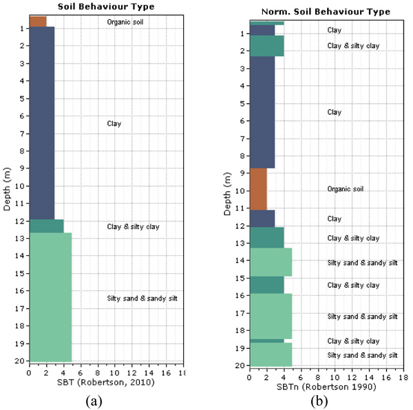
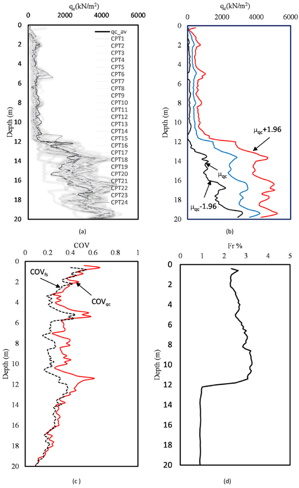
This section focuses on the statistical quantification parameters obtained from the CPT results. Figs. (2a and b) show the soil classifications using qc and normalized cone resistance. Clearly, the soil mainly consists of two layer types: the first has an approximately 12-m-thickness and the second layer has an 8-m-thickness. Fig. (3a) shows the relation between qc and the depth of the entire soil formation for all CPTs. The qcs values at depths between 0 and 12 are small and relatively low variability. The Figure also shows that in all CPTs, the qc begins to rapidly increase beyond a depth of 12 m until it reaches 20-m-depth. The mean qc value for the 24 CPT soundings was recorded at each depth, as shown in Fig. (3 b). The average qc was plotted against depth. The deviation is also presented in the Figure along with the qc average. The percentage of the friction ratio (Fr%), which is calculated based on the average qc and average fs increases gradually with depth until it reaches 12 m, which where the resistance ratio begins to decrease as shown in Fig. (3c). Between 12-m and 20-m-depth, the Fr is constant and small at approximately 1%.
The average value of the COV was calculated for every layer for both qc and fs. The COV for qc was less than 0.6 based on records of 24 soundings at 20-m-depth. Fig. (3d) shows the COV relationships for the fs and qc against depth. Notably, the variation coefficient of the sleeve friction (COVfs) is less than the tip resistance COV (COVqc) until depth equals 12-m, and then, they are relatively same. The COVfs and COVqc can be classified as highly variable [43]. The COVqc for the first layer of 12 m ranges between 20 and 40% and the mean is between 0.5 and 2. For the second layer of silty sand, the COV is less than 60, which ranges between 20 and 60. This confirms the conclusion outlined by [41] that the qc ranges infer the soil to be clay and silty sand.
4.2. Homogeneous Soil Unit
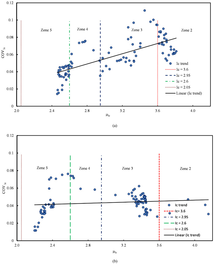
An analysis for identifying similar soil units has been performed based on the classification chart proposed by [55]. The classification chart consists of some zones, where every zone represents a soil type. These zones are isolated using curves developed according to normalized Ic for the normalized classification chart (SBTn) and according to ISBT for the non-normalized chart (SBT). The two methods show little difference [56]. The studied soil can be classified as the ideal soil where it is young and uncemented, and the chart used still can provide good results [53]. The ISBT mean and coefficient of variation COV of the ISBT were computed. Fig. (4) shows a scatterplot of the relation between the average Ic versus COV of the Ic. This indicates that the COV is less than 0.1 and the variability of the Ic increases slightly linearly as the zone number decreases i.e., from silty sand to clay. This finding is in contrast to the conclusion outlined by [33], where the COV tends to increase from the clay to sand zones. The thin soil layer can be discarded if it is located at the top or bottom of a thick layer of soil. Additionally, thin layers can be merged with other layers by averaging the qc, or by using SBT band or soil group approach proposed by [61]. According to these approaches, the soil profile at the site can mainly be classified into two similar unit layers: clay soil and silty sand with sandy silt.
4.3. Trend Removal Models
Several methods can transform the data from non-stationary to stationary data (e.g., differencing, variance reduction, and decomposition). The most traditional method applied in geotechnical applications is the decomposition process, which involves dividing the data into two components: trend and residuals [62]. Therefore, the first step in the computation of SOF is to remove the trend of the qc with depth (d) from the original data and compute the standard deviation of the de-trended qc (residuals) for every CPT using the best fit least square method.
Fig. (5a) shows the linear trend of the qc data for the 12-m-thick layer. The qc residuals with a zero mean are presented in Fig. (5b). Figs. (6a and b) show the quadratic polynomial trend with qc and the residual with depth, respectively. The cubic trends with depth for qc and residuals are presented in Figs. (7a and b). The factor for the occurrence of a spatial trend in the qc may be the overburden pressure [63]. The best trend function can be selected visually [29] or by using Kendall tau [64].
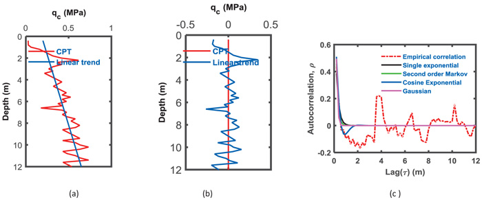
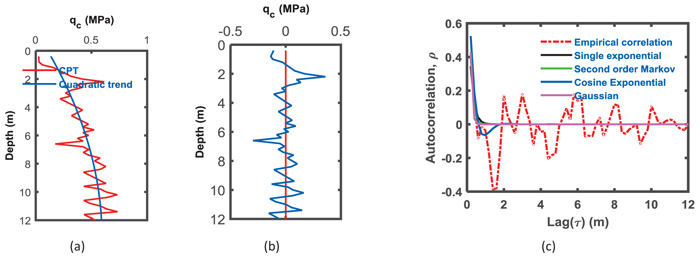
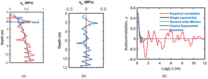
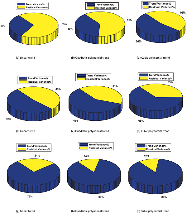
Fig. (8) shows a pie chart of the variance percentage removed from the qc data, which is conducted by removing the trend from the data for an average of 24 CPT soundings and is represented by the blue colored section. The yellow color represents the permanent variance remaining with a residual. Figs. (8a, b, and c) show the variation due to trend removal using three types of trends. For case 1, where the soil thickness is 12 m, removing the difference due to trend removal from the data, approximately 31% of the variance is removed when the linear function was chosen to represent the trend of the qc data. As the polynomial degree increases to a quadratic polynomial, the removed variation increases from 31% to 39% and increases to 54% when the trend removed is the cubic polynomial trend.
For the second case of 8 m, the general notice presented in the first case shows compatible results when the precedence of variance removed is different. The percentage of variance removed from the qc for the 8-m-thick layer was 52% when the trend was considered linear, while it increases to 59% for the quadratic trend removal and 65% for cubic trend removal Figs. (8d, e and f). The trend removal enhances the variance elimination of qc for the entire 20-m-layer of soil, where 76%, 86%, and 88% represent linear to cubic polynomial removals, as shown in Figs. (8g, h and i), respectively. The variance removal from the original qc data increases as the polynomial degree of the trend increases. Removing a second order polynomial reduces the residual variance by more than 50%.
4.4. Vertical SOF
The qc residuals were computed based on the three cases of trend functions: linear, quadratic polynomial and cubic polynomials, as presented in the previous section. Four ACFs were fitted on the experimental qc data using the least square method. Table 2 shows the computed SOF using four ACFs for CPT soundings with linear de-trended qc for the three cases of soil layers having thicknesses of 12 m, which is a sample of the results. This Table contains the values of the vertical SOF computed by four ACFs in addition to the statistical parameters of the SOF, which are represented by the mean value of the SOF, standard deviation and COV. The average value of the SOF and statistical parameters for all CPTs are presented in the last row of Table 3.
The SOF is very important and has an impact on the reliability of a geotechnical system, such as slope stability [65] and the SOF can be included in the MCS and finite element methods. The behavior of geotechnical problems is more complex when using the SOF compared to some characteristic dimensions of the problem. For example, when the SOF equals the width of the foundation, it records the worst case. The SOF reduces uncertainties and decreases the probability of failure [13]. When the SOF is low, the variability is high, which may affect failures in geotechnical applications.
| CPT No. | SNE | SOM | SQE | CSE | μSOF | σSOF | COV% | Min | Max | Range |
|---|---|---|---|---|---|---|---|---|---|---|
| 1 | 0.51 | 0.53 | 0.47 | 0.52 | 0.50 | 0.03 | 5.06 | 0.47 | 0.53 | 0.06 |
| 2 | 0.88 | 0.91 | 0.72 | 0.91 | 0.86 | 0.09 | 10.65 | 0.72 | 0.91 | 0.19 |
| 3 | 1.02 | 0.84 | 1.24 | 0.68 | 0.94 | 0.24 | 25.61 | 0.68 | 1.24 | 0.56 |
| 4 | 1.32 | 1.43 | 1.38 | 1.48 | 1.40 | 0.07 | 4.77 | 1.32 | 1.48 | 0.16 |
| 5 | 0.84 | 0.87 | 0.69 | 0.88 | 0.82 | 0.09 | 10.81 | 0.69 | 0.88 | 0.19 |
| 6 | 1.23 | 1.34 | 1.20 | 1.38 | 1.29 | 0.09 | 6.65 | 1.20 | 1.38 | 0.18 |
| 7 | 0.55 | 0.50 | 0.47 | 0.43 | 0.49 | 0.05 | 10.47 | 0.43 | 0.55 | 0.12 |
| 8 | 1.03 | 0.99 | 0.78 | 0.95 | 0.94 | 0.11 | 11.35 | 0.78 | 1.03 | 0.24 |
| 9 | 0.34 | 0.35 | 0.26 | 0.34 | 0.32 | 0.04 | 13.36 | 0.26 | 0.35 | 0.09 |
| 10 | 0.33 | 0.33 | 0.24 | 0.31 | 0.30 | 0.04 | 13.54 | 0.24 | 0.33 | 0.09 |
| 11 | 0.39 | 0.40 | 0.35 | 0.37 | 0.38 | 0.02 | 5.50 | 0.35 | 0.40 | 0.05 |
| 12 | 1.04 | 1.09 | 0.93 | 1.11 | 1.05 | 0.08 | 7.75 | 0.93 | 1.11 | 0.18 |
| 13 | 0.34 | 0.36 | 0.28 | 0.35 | 0.33 | 0.04 | 11.37 | 0.28 | 0.36 | 0.08 |
| 14 | 0.38 | 0.39 | 0.37 | 0.35 | 0.37 | 0.02 | 4.83 | 0.35 | 0.39 | 0.04 |
| 15 | 0.99 | 0.96 | 0.93 | 0.91 | 0.95 | 0.03 | 3.48 | 0.91 | 0.99 | 0.08 |
| 16 | 0.51 | 0.54 | 0.44 | 0.54 | 0.51 | 0.05 | 9.56 | 0.44 | 0.54 | 0.10 |
| 17 | 0.82 | 0.78 | 0.75 | 0.73 | 0.77 | 0.04 | 5.02 | 0.73 | 0.82 | 0.09 |
| 18 | 0.45 | 0.47 | 0.41 | 0.45 | 0.44 | 0.03 | 6.03 | 0.41 | 0.47 | 0.06 |
| 19 | 0.88 | 0.80 | 1.02 | 0.70 | 0.85 | 0.14 | 16.15 | 0.70 | 1.02 | 0.32 |
| 20 | 0.59 | 0.62 | 0.53 | 0.64 | 0.59 | 0.05 | 7.88 | 0.53 | 0.64 | 0.10 |
| 21 | 1.03 | 0.99 | 0.78 | 0.95 | 0.94 | 0.11 | 11.35 | 0.78 | 1.03 | 0.24 |
| 22 | 0.18 | 0.21 | 0.15 | 0.23 | 0.19 | 0.03 | 17.58 | 0.15 | 0.23 | 0.08 |
| 23 | 0.45 | 0.48 | 0.46 | 0.47 | 0.46 | 0.01 | 2.49 | 0.45 | 0.48 | 0.03 |
| 24 | 0.63 | 0.68 | 0.54 | 0.70 | 0.64 | 0.07 | 11.02 | 0.54 | 0.70 | 0.16 |
| Mean | 0.70 | 0.70 | 0.64 | 0.68 | 0.68 | 0.06 | 9.68 | 0.60 | 0.74 | 0.15 |
Based on the results displayed in Table 3, the SOF obtained using every method gives different results. This conclusion was attained with the mean, standard deviation and the COV. Notably, the location of the CPT gives approximately the same results. The average value of SOF (µSOF) for all CPTs is 0.64 m. The linear function with nonlinear experimental results does not reflect good consistency, which is an unsuccessful attempt to obtain the weak stationary data. Using the quadratic function may provide highly consistent results. Table 3 shows the results of the data residual with the second polynomial function. SOF equals 0.55 m, which means that the SOF decreases as the degree of polynomial increases. Fig. (9) shows a histogram of the SOF to compare the three trending methods. Clearly, the two methods of trending second and third polynomials are better than linear trending. The data became close to weak stationary as the higher degree of the polynomial was used.
Based on Table 3, the average SOF for the qc data of the linear detrend was 0.64 m, while it was 0.55 m for case 2 and 0.52 m for case 3. These values are in the SOF range obtained by [14]. For sand and clay, the vertical SOF was between 0.13 and 1.11 [33]. The average value of COVs for all CPTs for every case were 11%, 6%, and 9%. They show a low level of variation for SOF.
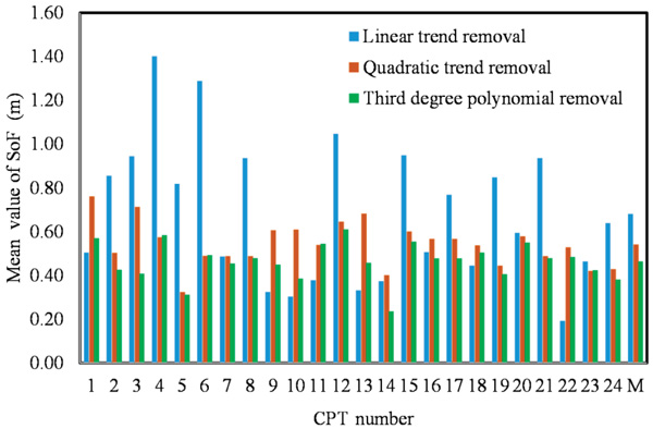
Considering the eight-meter soil layer, the SOF was calculated using four ACFs and the data was transformed using three trending methods. The µSOF for all CPT soundings was 0.63 m between a minimum of 0.32 and maximum of 1.01 m, which are located between the 0.1 and 2.2 m reported by [41, 32]. The SOF average is linearly reduced with an increasing trend function degree. The SOF decreases to 0.53 m when using the residual data of the polynomial function, and it becomes 0.47 m with a minimum of 0.24 and maximum of 0.6 for the third-degree polynomial. The SOF results indicate that the values of SOF decrease as the trend function degree increases i.e., the fitting is enhanced. This conclusion confirms that which was reported by [2]. Fig. (9) shows the apparent effect of the de-trending method, in which a bar chart was used to demonstrate the height of the first bar showing the small degree of trend removal is mostly greater than for the other types. The high degree of polynomial trend removal shows a minimum SOF value. The correlation function effect used in this study of the SOF was relatively small. As an average range for all CPT soundings, which is the difference between maximum and minimum, SOF was 0.12 for the linear de-trend, decreased to 0.11 for the second polynomial and 0.094 for the third polynomial removal of data. The COV% for SOF as an average for all CPTs were 9.17 for linear, 9.51 for quadratic polynomial and 9.65 for the cubic polynomial. It slightly increases with an increasing degree of trending removal. The COV obtained in this study for qc can be classified as low variability for SOF as provided by [43], where the COV is low if it is less than 15% and moderate between 15% and 30%.
| Item | Trend type | Thickness (m) | SNE | SOM | SQE | CSE | μSOF | σSOF | COVSOF% | Min | Max | Range |
|---|---|---|---|---|---|---|---|---|---|---|---|---|
| 1 | Linear trend | 8 | 0.60 | 0.66 | 0.56 | 0.68 | 0.62 | 0.06 | 9.18 | 0.56 | 0.68 | 0.12 |
| 2 | Second degree | 8 | 0.51 | 0.57 | 0.50 | 0.59 | 0.54 | 0.05 | 9.49 | 0.49 | 0.60 | 0.11 |
| 3 | Third degree polynomial | 8 | 0.43 | 0.49 | 0.43 | 0.51 | 0.46 | 0.04 | 9.65 | 0.42 | 0.51 | 0.09 |
| 4 | Linear trend | 12 | 0.70 | 0.70 | 0.64 | 0.68 | 0.68 | 0.06 | 9.68 | 0.60 | 0.74 | 0.15 |
| 5 | Second degree | 12 | 0.51 | 0.54 | 0.47 | 0.54 | 0.51 | 0.04 | 8.56 | 0.46 | 0.55 | 0.09 |
| 6 | Third degree polynomial | 12 | 0.39 | 0.42 | 0.38 | 0.42 | 0.40 | 0.03 | 8.21 | 0.37 | 0.43 | 0.06 |
| 7 | Linear trend | 20 | 2.57 | 2.78 | 2.65 | 2.86 | 2.72 | 0.21 | 7.90 | 2.51 | 2.97 | 0.46 |
| 8 | Second degree | 20 | 1.29 | 1.37 | 1.26 | 1.40 | 1.33 | 0.09 | 7.23 | 1.23 | 1.42 | 0.20 |
| 9 | Third degree polynomial | 20 | 1.12 | 1.18 | 1.10 | 1.19 | 1.15 | 0.07 | 6.68 | 1.06 | 1.22 | 0.16 |
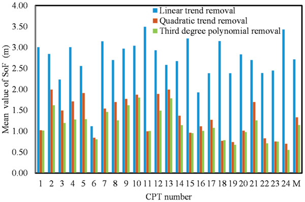
The SOF computation for the two-layered soil is considered to be one layer with a thickness of 20 m, and based on qc, shows high SOF values. The average for all values of the CPTs equals 2.68 m and the standard deviation, σSOF, equals 0.21, which is out of the data range for the SOF values reported by [32], where the SOF in the vertical direction is between 0.1 and 2.1. The increase in the SOF compared to the values previously obtained and presented in the last paragraph for every individual layer may be attributed to the nature of qc, which represents a different type of soil and reflects different behaviors, making the linear trend removal insufficient for obtaining the weak stationary data. Using the second order polynomial removal, which represents the qc data well, shows a decrease in the SOF. It will equal 1.36 as an average value and range between 0.74 and 1.992. Applying the cubic polynomial function for trend removal of data decreases the SOF to 1.17 as an average for the values of all the CPT between 0.67 and 1.8 with the σSOF equal to 0.07. One can conclude that the cubic polynomial is required for data that show as strong stationary, which requires data manipulation to transform it to weak stationary. The COVSOF equals 6.44% as an average value for all CPTs, which is located between the minimum value of 1.52% and the maximum value of 13.34%.
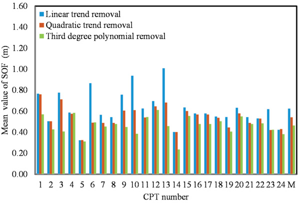
Histograms of computed SOF based on de-trended qc utilized three trend functions, including linear, quadratic and cubic polynomials, and are shown for every CPT (Figs. 9, 10 and 11). The adjacent bars in all histograms for every CPT indicates that SOF decreases as the degree trend function is increased. For example, Fig. (9) shows how the SOFs for qc were de-trended with the linear trend function removal and indicates high values compared to SOF for qc de-trended with quadratic and cubic polynomial functions. The SOF mean obtained using four approaches was 0.37 for the second polynomial removal with a thick layer of 20 m. Comparing this value to that of the 12 m and 8 m layers indicates that the SOF for the entire layer with stratigraphic layers reveals a high SOF. It is recommended that the SOF be evaluated for every layer to obtain accurate results. When the cone resistance from the entire depth of 20 m is considered, the cone resistance is strongly correlated to an average distance of 1.149 m.
CONCLUSION
A refinery oil enhancement unit is being constructed in Nasiriyah and reliability of the geotechnical design (e.g., foundation engineering) is necessary, and thus, computation of the soil spatial correlation is conducted. Twenty-four CPT soundings for the Nasiriyah site were utilized to compute the SOF for qc. No soil information with stochastic analysis was available for Nasiriyah. Three modes of soil are used in this study: the first is considering the soil as two layers of clay and silty sand and the second is considering the entire layer as one layer. Four correlation functions are used to compute the scale of the fluctuation and three approaches of de-trending are used: linear of residual and the second and third polynomials. The following conclusions are drawn from this research.
- The mean SOF value obtained using different correlation function procedures for total CPTs performed on soil in Nasiriyah were 0.68, 0.51, and 0.4 utilizing 12 m thickness layer for three trend functions; 0.62, 0.54, and 0.46 for a layer of 8m thickness; and 2.72, 1.33, and 1.15 for the entire 20-m thick layer.
- De-trended qc based on three functions were performed on the soil in Nasiriyah and showed a clear effect on the scale of the fluctuation. The degree of polynomial increases, the µSOF decreases and the fitting is better for the 12 m soil layer case and for the other layers of 8 m and 20 m.
- The COV% for the SOF obtained using a different approach for each of the three soil models was 9.62, 8.64, and 8.37 for the model 1 soil with a 12-m-thickness; 9.17, 9.51, and 9.65 for model 2; and 7.86, 6.87, and 6.44 for the entire soil formation. Comparing the COVSOF value of this study with that of the literature indicated that there is a small range of variability.
- The variance reduction percentage of the qc data increases as the polynomial trend function degree increases. Removing the linear trend from the qc data leads to 31% removal of variance due to the trend and the percentage increases to 39% for the quadratic polynomial trend and 54% for the cubic polynomial trend removal.
CONSENT FOR PUBLICATION
Not applicable.
CONFLICT OF INTEREST
The corresponding author states that there is no conflict of interest.
ACKNOWLEDGEMENTS
The researcher expresses his sincere thanks to the Ministry of Higher Education and Scientific Research (MOHESR) and the University of Thi-Qar for the general support provided to achieve the scientific research.


