All published articles of this journal are available on ScienceDirect.

Installation and Maintenance Principles of Seismic Isolators: Erzurum Health Campus
Abstract
Background:
The objective of isolation is to reduce the seismic forces transmitted through the structure using active and/or passive insulation systems.Seismic isolators, which are passive insulation systems and are placed between the foundation of the structure and the structure, are discussed throughout this study. Isolators consist of rubber layers that have horizontal flexibility, steel layers that increase rigidity and a lead or ball core, which increases vertical stiffness. Installation and maintenance of seismic isolators require great care in order not to exceed the displacements/section forces envisaged at the design of the structure during the earthquake.
Objective:
Installation and maintenance principles of the friction pendulum type isolators used in Erzurum Health Campus (hospital) are presented throughout this study. While the seismic isolators are anchoraged to directly concrete in the general application, they are placed between two steel plates of type S355J2 in this application, because of cold-weather conditions. To evaluate this condition, the models with and without steel plate are compared to each other.
Methodology:
The models with and without steel plate were formed using finite-element method to compare the stress distributions on the isolator.
Conclusion:
The results demonstrated that the model with steel plates occur the uniform stress through surface and keep under control deformation of cross-section in the reinforced concrete.
1. INTRODUCTION
Ground-movements that occur during the earthquake transfer kinetic energy to the structures. Earthquake engineers try to limit the damage caused by this energy and observe its size, location. In particular, structures such as hospitals and emergency centers should be able to maintain their functions after major earthquakes for the health and safety of the people. In recent years, seismic installation for buildings and bridges has become a popular earthquake resistant design method all over the world.
The working principle of isolation is to reduce the seismic forces transmitted to the structure by the rigid elements in the vertical direction, and by flexible elements in the horizontal direction placed in the building base; and to absorb the seismic energy and movements. The technical advantages of this method are shown experimentally [1, 2], numerically [3, 4] and by finite-element models [2]. In addition, some researchers [5] evaluated the seismic isolation method comparatively by performing non-linear analyses with the help of static analyzing programs. Kubin et al., [6] evaluated the seismic performance of the Erzurum Health Campus, which is presented by exemplifying the insulators in this study. In the design process, researchers [6] addressing limiting isolator characteristics have demonstrated by the analyses that the isolators improve hospital's earthquake performance.
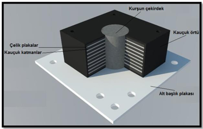
Base isolation systems play a damping role while the earthquake forces transmit to the structure. Thus, it is provided that stress/deformations transferred into the structure remain within the limits which the structure can carry. The isolators especially allow to distinguish the influence of horizontal loads from the vertical load effect. Thus, it is provided that stress/deformations transferred to the structure remain within the limits which the structure can carry. The isolators especially allow to distinguish the influence of horizontal loads from the vertical load effect, and made from a rubber, which is enough strong to support the building but allowing horizontal motion without breaking, a core such as ball, lead, which increases rigidity in the vertical direction, and steel plates. There are also layers in the rubber, where they provide rigidity in the vertical direction, limit the shape change of the rubber layers, and increase the rigidity in the vertical direction by wrapping the lead core. In summary, the rubbers of the isolators used in the earthquake provide horizontal motion (flexibility) while the steel plates provide rigidity in the vertical.
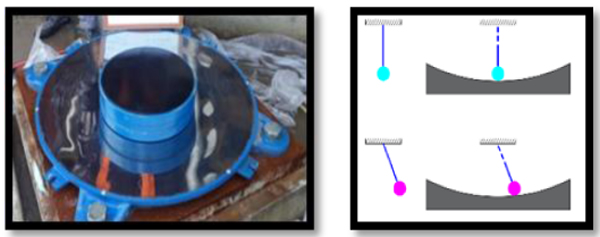
There are various types of base isolators with square or circular cross-section. The isolators made of rubber and steel plates in the layered form have to lead or ball cores within them. The lead-rubber seismic isolator illustrated in Fig. (1) is used commonly. The friction pendulum type insulator, which is the basis of this study and applied in Erzurum Health Campus, is presented in Fig. (2a). The basic elements of this isolator are: concave (or rounded) bearing surfaces and spherical balls placed between them. Sometimes cylindrical elements which only provide to move in one direction can be used instead of the balls. This movement is a transformation to potential energy [7], which occurs the effect of coming to a natural center, like a pendulum Fig. (2b). The centripetal force is proportional to the mass, and the natural period of the isolator is independent of the mass of the element to be isolated [8].
One of the reasons for seismic isolation is to reduce the effect of earthquake forces on the structure. Thus, the structure remains within the permissible displacement limits envisaged in the design. Seismic isolators must be installed and maintained properly, in order that the stress remains within the elastic limits, and the structure shows the rigid behavior expected during the earthquake. In these systems, isolator requires to have a 0% slope on the plane on which the isolator will be placed. So that, the ball can follow the motion principle. Therefore, it is important that the isolator is placed properly in the application area and that the upper and lower plates of the isolator are correctly positioned and rigid. In this study, the installation principles of isolators in the construction-site are explained. In addition, after the isolators are installed, it is necessary to maintain periodically depending on the type of isolator. In particular, the outside isolators are more affected by external environmental influences such as air, water dust, etc. This situation affects the smoothness of the upper and lower plates negatively and prevents to work the ball full performance during the earthquake. In this study, the maintenance principles to be done for the friction pendulum isolator examined are also given in this study.
Concrete anchorages are usually installed directly to the base isolators in the construction-site. In cold weather, the possible volume change resulting from freezing water inside the concrete can adversely affect the surface slope which should be 0% of the isolator steel plates. The isolators in the Erzurum Health Campus are anchored between S355J2 grade steel sheets in varying thickness (20 mm-80 mm). In this study, the use of C50 concrete (concrete with a characteristic pressure of 50 MPa) and S355J2 grade steel in the isolator installation was modeled with the finite-element, and compared to each other.
2. ISOLATION ANCHORAGE TO CONCRETE: via STEEL PLATES OR DIRECTLY
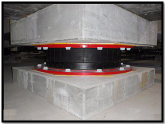
The anchor bolts are welded to the foundation reinforcement bars before the foundation concrete is poured. Then, Seismic isolators are placed directly on the concrete by passing the anchor bolts through the bolt holes in the steel plates on the upper and lower sides (e.g. Erzurum Education Hospital isolator application). The insulators are usually placed after the surface has been leveled with grout on C50 concrete. The bolts on the upper plate of the isolator are fixed to the reinforcement bars before the floor concrete is poured, and thus it is provided them to work together after the concrete is poured (Fig. 3).
With the assumption that the lowest temperature in fresh concrete is at 5 degrees, the regions where the average daily air temperature is below 5 degrees for 3 days and the temperature is below 10 degrees during the half day within the 3 days is defined as cold weather zones in terms of concrete casting in the literature [9]. When the average annual temperatures of the Erzurum, which is the application area of isolators examined in this study, are evaluated. It is observed that, the air temperature is over 5 degrees for just 4 months [10]. During concrete pouring in cold weather and after achieving the standard strength of concrete, some problems can occur. While concrete pours in cold weather, the volume of concrete changes due to the water freezing in the concrete or due to the moisture movements in the hardened concrete [9], and additional stresses occur due to this.
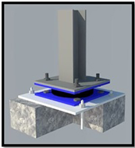
In structures with seismic isolation, while the isolators are generally directly anchored to reinforced concrete; considering the cold weather conditions in Erzurum, the isolators at the Erzurum health campus hospital building were installed between steel plates. Grout is also applied on foundation concrete in order to ensure that the surface is smooth and in full contact of the steel. Thus, the loads can be transferred to the base uniformly. The crusts and cracks that may form on the concrete surface in cold weather can impair adherence, stability and the load transfer between the concrete and the isolator. The volume expansion of the concrete, which is the most important disadvantage of concrete casting in cold weather, can also cause to fail the surface slope (0%). The surface slope has to be carefully provided for the correct operation of the ball of the isolator core in the isolator installation. In order to control the volume change of the concrete during cold weather due to the temperature variation, it is taken precautions with some additives (air entraining admixtures, etc.) can be used in course of the concrete manufacturing. However, using steel plates is appropriate as a more permanent solution to not adversely affect the behavior of isolators and to control the deformations that can occur in cold weather, and for ease of application. For this reason, the behavior of the isolator can be achieved on the reinforced concrete member using the steel S355J2 in the thickness between 20 and 80 mm depending on the application Fig. (4). The S355J2 steel is 27 j energy absorption steel at -20 oC with the lowest yield strength of 355 MPa.
The most prominent feature of the S355J2 steel plates which is placed between the isolators compared to normal steels is that they can absorb 27 joules of energy in the Charpy V-notch experiments at -20 °C. Charpy V-notch experiments, which are performed at temperatures between (-20 ° C) - (+ 20 ° C) show that the steels with relatively high-carbon content are not affected in terms of energy dissipation capacities from temperature changes. However, the energy dissipation capacities of structural steels with low carbon content are quite low at temperatures below 0 oC [11]. The use of special steels whose energy dissipation capacity is same with normal steel is recommended.
3. FINITE ELEMENT MODELLING OF BASE ISOLATION SYSTEM
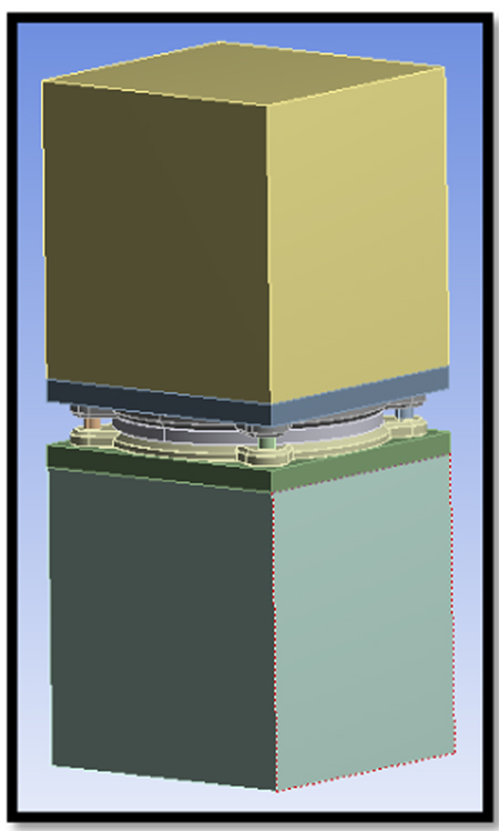
In this study, it is aimed to compare the stress distributions on the isolator by modeling in the ANSYS Workbench v16 program. The load distribution inner part of a column is a very important point for design purposes of seismic isolators. Thus, the symmetrically application of loads not only improves the behavior of the column, but also the behavior of the investigated isolator system. To decide the best application system for the base isolator, this modeling work has been adopted. The first model was simulating the directly connection of the isolator, and the C50 concrete; the second one was simulating the connection of the St355J2, the steel plate, and the isolator. The ANSYS-Workbench [12] is used for predicting compare the stress distributions on the isolator of the numeric models. The concrete and the steel are modeled as solid elements. One of the most important steps in finite-element (FE) analysis is the creation of mesh structure. The sweep, automatically generated, tetrahedrons and hex-dominant are meshing method in ANSYS-Workbench program. The sweep method cannot be used in plate or concrete connection models. The non-sweepable bodies force the sweep method controlling. The automatically generated, tetrahedrons and hex-dominant method meshing compare their created nodes and elements for the same sizing. Thus, as a result of research for CLI model is used to mesh with these generation types from the guidance of some given literature [2, 5] and elsewhere. The mesh size is taken as 50 mm for each method. It is observed from the Table 1 that, automatically generated tetrahedrons and hex-dominant meshing methods give different values for nodes and elements.
| Mesh Type | Number of Nodes | Number of Elements |
|---|---|---|
| Automatically Generated | 29998 | 9998 |
| Hex-Dominant | 25236 | 8419 |
| Tetrahedrons | 31826 | 10628 |
Therefore, tetrahedron meshing with 10-node (every node of this volume has three degrees of freedom) selected for solving FE models. Mesh sizing is important for accurate stress value. For this purpose, selected meshing type, the tetrahedron mesh divides various sizing mesh starting with 300 mm. When the stress and displacement values are stable, this mesh sizing can be applicable for FE analysis. Table 2 and Fig. (5) illustrate that mesh sizing is important to find the exact stress values.
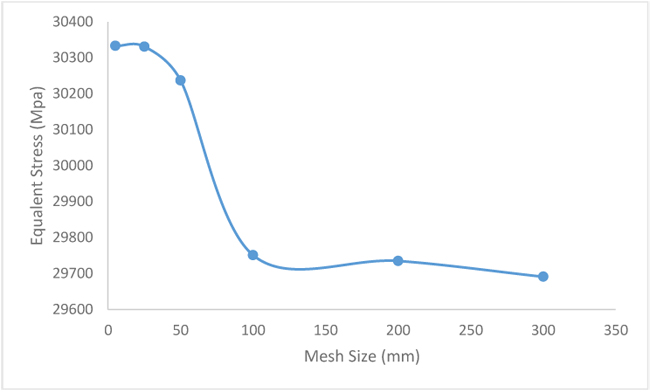
| Mesh Size (mm) | 5 | 25 | 50 | 100 | 200 | 300 |
| Von Mises (MPa) | 30333 | 30331 | 30237 | 29751 | 29735 | 29691 |
Furthermore, Fig. (5) shows the maximum stress values of the models, and 5, 25 and 50 mm mesh sizing are similar. The variation of the stress values is becoming very rough, and as seen from the Fig. (5) , the curve is becoming asymptotic for less than five mm mesh size. Because of the memory allocation and computer analysis time problems, the mesh size is decided as 50 mm for FE analysis. Fig. (6) shows that, the model is simulated by using the nonlinear finite-element method (FEM), and the results are presented by taking a section of the foundation under the isolator and the underlying reinforced concrete. In the Sap2000 program, 30 kN axial pressure load, which is the critical column load, was analyzed through the column.
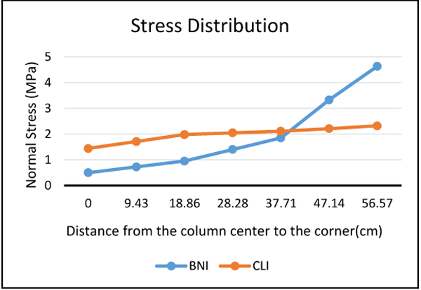
Fig. (7) shows the maximum normal stress curves obtained from the results of the FE analyze of the isolator model using steel plates and the isolator model directly placed on the concrete Fig. (8) and Table 3 shows the minimum and maximum normal and shear stresses. Fig. (9) shows a stress distribution curve that summarizes the purpose of the study. In this curve, the center of the column with dimensions of 80 x 80 cm is considered as the center “0” point and the distance to the column corner is divided into 6 equal distances (6 x 9.43 cm = 56.57 cm) stresses were measured. In this curve, it is seen that tension is uniformly distributed between the column center and the column corner for the CLI, while tension increases from the center to the corner for the BNI. As can be seen in the curves and figures, using steel plates on the upper and lower sides of the isolators ensures that the stresses on the isolator are reduced and the upper base transfers the building's load more uniformly. In other words, steel plates which facilitate the manufacturing process will be able to transfer the appropriate load in terms of insulators if the application is done correctly.
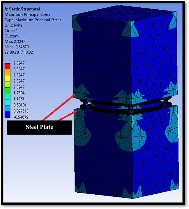
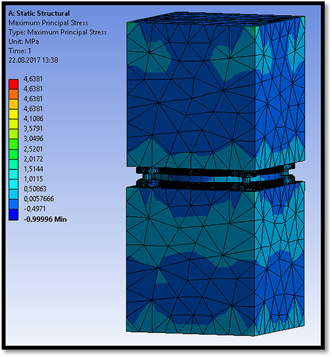
| Maximum Shear Stress | 1,7230 | 2,5908 |
| Maksimum Normal Stress | 2,3247 | 4,6381 |
| Minimum Normal Stress | -0,5468 | -1 |
4. INSTALLATION PRINCIPLES OF SEISMIC ISOLATIONS IN SITE
The installation in the construction-site of seismic isolators is an application that needs to be done precisely. The installation steps of the steel plates placed on the upper and lower sides of the isolators and isolators used in the Erzurum Health Campus are given below:
-
Installation and fixing of bottom dowels: The installation of the isolators starts with the placement of the dowel which is served as a bolt hole to the lower base. The dowels are installed with the help of a steel gage plate cut on CNC benches, taking into account the type of isolator on the project (Fig. 10). Using the red table illustrated in Fig. (11) in coordination with the map technician, the grade and distances are adjusted and the dowels are fixed to the bars by means of the steel gage plate.
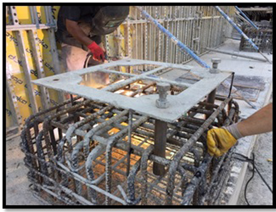 Fig. (10). Installation of bottom dowels and steel gage plate.Elevations such as grout clearance, steel gage plate clearance, adhesive clearance should not be neglected when the grades are adjusted. Before placing the lower plate and isolator, the screws, which is provided ease of manufacture, to be able to precisely adjust the position and reset the slope after the isolator is installed is welded onto dowels. (Fig. 12). After the dowels are placed and fixed, the steel gage plate is removed from the system and concrete is poured (Fig. 13).
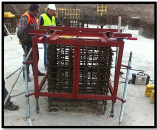 Fig. (11). Installation of bottom dowels and steel assistant table.
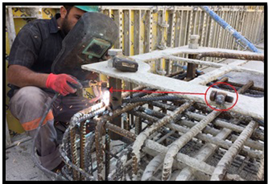 Fig. (12). Welding bolts to isolator’s bottom dowels.
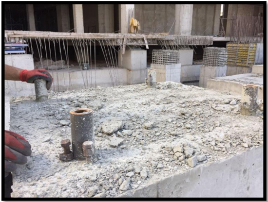 Fig. (13). Isolator’s bottom dowels and assistant bolts.
 -
Placement of the lower plate and preparation phase: After the concrete pouring, the lower steel plate to be used at the bottom of the isolator is installed (Fig. 14). The steel plates to be used at the top and bottom of the isolator in the project are given in various sizes and thickness according to the size of the isolator. It should be important using cold-sawing in water-jet CNC machines while cutting these plates. Furthermore, care should be taken to drill these holes in accord with the diameter of the bolts to be used with the cold drilling machine. Cold-sawing and cold-drilling reduce the tensile ratio and prevent to occur thin cracks. After the plates are cut, the plate surfaces must also be lathed (in one side) and straightened. Small ripples on the plate surface during the rolling phase will prevent to fix in the place of the isolator and will render the system unusable. In addition, the small gaps on the plates must be eliminated. The laminate process is performed until a smooth surface is obtained. After this process is conducted, shot blasting on the plates should be done to increase the resistance against corrosion and to prevent rust in seasonal conditions. Fast-acting double-component zinc based epoxy primer (Shop primer) and two layers of zinc based paints were also applied on the plates in the site. As shown in Fig. (15), before the grouting of the lower steel plate is poured, the surface slope, which must be achieved, is provided by means of the screws previously welded on the dowels.
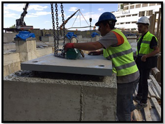 Fig. (14). Installation of bottom plate.
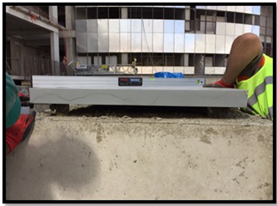 Fig. (15). Process of the required slope.
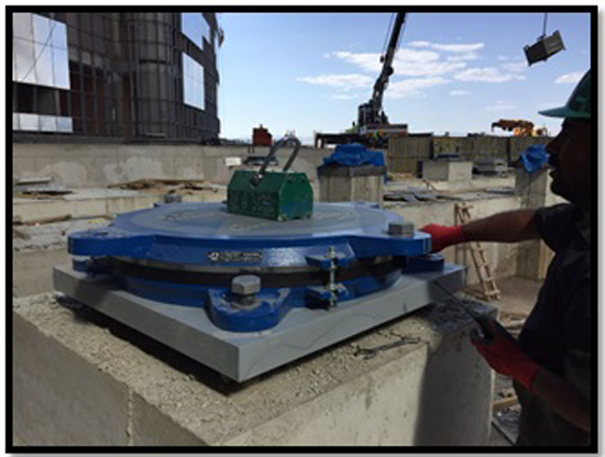 Fig. (16). Installation of isolator.
 -
Installation of isolators: After installing the plates, isolators are placed on the plate taking care of the x and y axes. Hydraulic pressurized torque device is set to the torque values taken part for isolators in the project and the bolt tightening operation is performed, and the isolator installation process is completed as in Fig. (16).
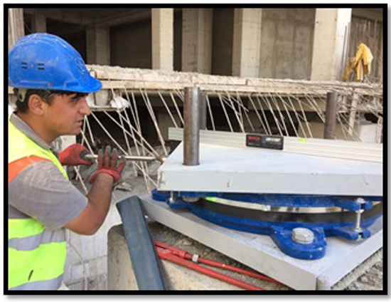 Fig. (17). Installation of top plate.
 - Placement of the upper bolts and plates: The upper bolts as upside down are prepared by fixing the isolator, in order that the isolator is assembled to the upper base. After the upper bolts are tightened, the upper plate, which is the same as the lower plate, is placed in the system and the isolator installation process finished (Fig. 17).
-
Grout processing: After the isolator installation is completed, it is necessary to fill between the steel plate and concrete. For this purpose, grout mortar is filled by applying vibration. Thus, it is ensured that the bottom steel plate is fully seated on the surface of the reinforced concrete (Fig. 18).
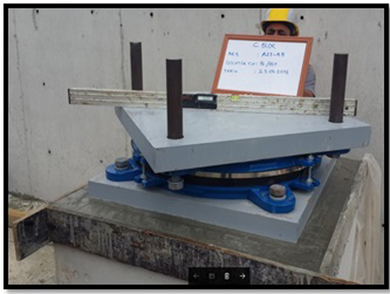 Fig. (18). Isolator installation.
5. MAINTENANCE PRINCIPLES OF SEISMIC ISOLATORS
During the earthquake, the inner surfaces of the isolation steel at the bottom and top of the ball is required to be smooth so that the movement of the ball in the isolators can be performed correctly. Furthermore, especially base isolators in outside are affected by external conditions due to contact with air and water. After the isolator system is installed, it is necessary to maintain the isolators periodically depending on the type of isolator. Ball isolators need to be checked every five years. Isolators can be installed inside and outside the building depending on the architecture and/or the frame system of the building. Isolators in the interior are less affected by the external environmental influences, but dust accumulates in the interior over time. If these dust deposits are in the oscillating reservoir of the curved ball, it will prevent the expected performance of the ball during the earthquake. Isolators used in the outdoors lead to corrosion on the upper and lower plates of the ball with the effect of air and water, and again the working principle of the isolator is broken. This prevents the isolator from performing the intended release.
During the maintenance of the isolators, the considerations to be taken into account are as follows:
- The isolators of the building must be individually maintained. Firstly, the full weight of the building and the axial load on each isolator are calculated. Accordingly, the building is lifted, and the isolator is opened in the part which will be maintained by using the hydraulic jack system. After the steel plates of the isolator has been maintained and re-installed. Then, it is continued with the isolator.
- After the upper plate of the ball is opened in each isolator, the lower and upper plates are cleaned by air with special compressors without touching. Then the ball is put in its place and is closed the top plate. The air compressor must be used horizontally during cleaning. Otherwise, scratches may form in the isolator oscillation chamber, and these scratches will disturb the smoothness of the oscillation chamber and prevent the expected oscillation of the ball.
- If the ball motion or for some other reason is caused scratches in the headers of the top and bottom plates, these scratches will disturb the smoothness of the plates and will prevent the proper functioning of the ball, in this situation the isolator must totally change.
CONCLUSION
In the seismic isolation method, the isolators mainly consist of a lead, ball, etc., which is increasing the rigidity in the vertical direction and a rubber which is allowing a certain amount of horizontal movement and a steel plates which is limiting the damping effect and the movement of the rubber in the horizontal direction. The uniform distribution of axial loads of column is obtained by steel plates and verified by the FE models, in this study. The uniformity of load transformation not only resulted longevity of reinforced concrete members, but also the expected movement and response of the isolators. In order that the building is able to demonstrate the rigid behavior expected during the earthquake, this method should be implemented appropriately. Installation and maintenance principles of seismic isolators by based on friction pendulum bearing isolators used in Erzurum Health Campus (hospital) presents in this study. Furthermore, installation of the isolators to the concrete in the mentioned hospital was performed between two steel plates of S355J2 grade. The mentioned steel type is another point to be considered for environmental conditions. However, the purposes of the mechanical design concepts are taken into consideration in the FE analysis, the selection of the material (steel and/or concrete) type is another phenomenon for especially cold-weather construction sites. Thus, an innovative engineering thinking method have to be applied for any construction process. The cases where the isolators are anchored directly to the concrete and are anchored using steel plates are modeled. Using steel plates on the upper and lower sides of the isolators has been shown to provide lowering maximum stresses and that the upper base transfers the building's load more uniformly to lower base, as well as the ease of installation. That is, if manufacturing and installation of steel plates are performed correctly, appropriate load transfer which is important for insulators will be provided.
CONSENT FOR PUBLICATION
Not applicable.
CONFLICT OF INTEREST
The authors declare no conflict of interest, financial or otherwise.
ACKNOWLEDGEMENTS
The authors wish to thank HEKTAS Construction Company which is the contractor company and GENCLER Metal Steel Company which applied the isolators in the construction.

