All published articles of this journal are available on ScienceDirect.

Structural Behavior of Geopolymer Concrete Thin Wall Panels Based on Metakaolin and Recycled Concrete Aggregate
Abstract
Introduction:
Due to the current popularity of Reinforced Concrete (RC) wall construction and the new published codes for concrete, RC walls have become just as important structural elements as beams, slabs and columns.
Methods:
This paper presents the structural behavior of geopolymer concrete thin wall panels based on metakaolin and recycled concrete aggregate subjected to axial eccentric uniformly distributed loading with varying Aspect Ratios (AR=H/L) and steel reinforcement ratios. The experimental program includes testing of five two-way thin geopolymer concrete wall panels; fixed at all sides and applying the load axially with eccentricity equal to the wall thickness/6.
Results and Conclusion:
The results indicate that the load-carrying capacity of the geopolymer concrete wall panels increased to about 63% with a decrease in AR (H/L) from 1.875 to 0.75. The lateral deflection decreased to about 50% with a decrease in AR (H/L) from 1.875 to 0.75. Also, the results show that the load-carrying capacity of the geopolymer concrete wall panels increased to nearly 48% with an increase in the steel reinforcement ratio from 2.32% to 3.38%. The lateral deflection also decreased by 20% with an increase in the steel reinforcement ratio to 3.38%. The results show that locally manufactured Metakaolin can be used for producing Geopolymer concrete.
1. INTRODUCTION
Several studies have been carried out to reduce the use of Portland cement in concrete and to address the global warming issues. These studies include the utilization of supplementary cementing materials such as fly ash, silica fume, granulated blast furnace slag, rice husk ash and metakaolin. Besides that, they also include the development of alternative binders to Portland cement [1].
The term geopolymer was introduced by a French Professor, Davidovits, in 1978 to represent a broad range of materials characterized by networks of inorganic molecules (Geopolymer Institute) [2-4] The geopolymers depend on thermally activated natural materials like Meta kaolinite or industrial byproducts like fly ash or slag to provide a source of Silicon (Si) and Aluminum (Al). Silicon and Aluminium are dissolved in an alkaline activating solution and subsequently polymerize into molecular chains and become the binder. Professor B. Vijaya Rangan, Curtin University, Australia, stated that the polymerization process involves a substantially fast chemical reaction under alkaline conditions on silicon-aluminum minerals that result in a three-dimensional polymeric chain and ring structure [5]. The ultimate structure of the geopolymer depends largely on the ratio of Si to Al (Si:Al), with the materials most often considered for use in transportation infrastructure typically having a Si:Al between 2 and 3.5 [6, 7].
Metakaolin (MK), Al2Si2O7, is a largely amorphous dehydration product of kaolinite, Al2(OH)4Si2O5, which exhibits strong pozzolanic activity. Metakaolin is processed from kaolin clay by calcination at a moderate temperature between 650-800 oC. At higher temperatures (> 900 oC), metakaolin is subjected to other reactions to form crystalline compounds, the final products that are free silica and mullite. The main reasons for using clay-based pozzolans in mortar and concrete are the availability of the materials and durability improvement. Depending on the calcination temperature and the type of clay, it is also possible to obtain improvements in strength, particularly during the early stages of curing [8]. Used together, geopolymer concrete and recycled concrete aggregate eliminate the need for Portland cement and make use of waste materials. Significant research has been carried out on both Recycled Concrete Aggregate (RCA) ordinary concrete Portland cement and geopolymer concrete; however, there were limited data published on the use of RCA in geopolymer at the time of this investigation. Therefore, the objective is to investigate the mechanical properties of geopolymer concrete with the addition of recycled concrete as a partial replacement of natural coarse aggregate [9]. Reusing construction waste fulfils two aims; the first is to remove large quantities of pollution resulting from this waste, and the second provides cheap resources for concrete aggregates [10]. In 2001, Sabir et al. reported that the use of Metakaolin as a pozzolana helps in the development of early strength and some improvement in the long term strength [11]. In 2018, Ashraf et al. investigated that the use of the recycled concrete aggregate is slightly beneficial in improving the mixture by the use of fly ash and that the concrete strength increases when the amount of the RCA increases [12].
2. OBJECTIVE AND IDEA OF THE CURRENT STUDY
- 1- To produce environmentally friendly concrete and eliminate CO2 emissions from OPC.
- 2- To test the use of this type of concrete in the production of walls panel.
- 3- To utilise concrete waste from structure and demolition sites, that would else be disposed off into landfills, as a source of recycled aggregate which proposes a potential environmental and economic benefit.
- 4- To study the structural behavior of wall panels under uniformly distributed axial load.
2.1. Experimental Work
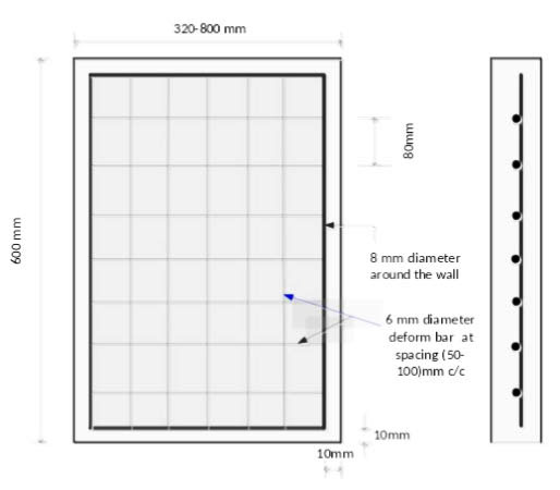
The experimental program includes casting and testing of five geopolymer concrete wall panels. All the tested walls are fixed supported in two dimensions and subjected to uniformly distributed axial loads with an eccentricity of t/6 from thickness. The slenderness ratio (H/t) and thickness of all the specimens are 15 and 40 mm, respectively. The tested panels are divided into two groups, the first group, Group A, consists of three panels with varying aspect ratios (H/L) of 0.75, 1.5 and 1.875, while the second group, Group B, consists of three panels with varying reinforcement ratios ρ of 0.0267, 0.0338, and 0.0232. Tables 1 and 2 show the panel designations and dimensions for Groups A and B, respectively. Fig. (1) shows the arrangement of reinforcement in the panel.
| Wall Panel | Dimensions (mm) | Aspect Ratio (H/L) | Steel Reinforcement |
|---|---|---|---|
| WG1 | 600 x 320 | 1.875 | 0.0267 |
| WG2 | 600 x 400 | 1.5 | 0.0267 |
| WG3 | 600 x 800 | 0.75 | 0.0267 |
| Wall Panel | Dimensions (mm) | Aspect Ratio (H/L) | Steel Reinforcement |
|---|---|---|---|
| WG4 | 600 x 400 | 1.5 | 0.0232 |
| WG2 | 600 x 400 | 1.5 | 0.0267 |
| WG5 | 600 x 400 | 1.5 | 0.0338 |
3. MATERIALS AND METHODS
3.1. Metakaolin
Metakaolin is the white powder of Al2O32SiO2 dehydrating kaolin (Al2O3 2SiO3.2H2O) burned to an appropriate temperature of 700-900 °C. Kaolin is a layered silicate structure; the layers are bound to each other by a Van Der Waal's bond, between which O is firmly tied. Kaolin, when heated in air, may experience several structural changes and when it is heated to around 600° C, the stratified structure of kaolin is damaged due to dehydration to form a transient phase with poor crystallinity, metakaolin. While the molecular arrangement of metakaolin is irregular in thermodynamic condition it is found stable under suitable excitation. With high activity, metakaolin can be used to manufacture cemented materials and mix high-strength and high-performance concrete [10]. The chemical analysis of Metakaolin, and Chemical requirements of Pozzolan ASTM C 618 [13] are illustrated in Table 3 and 4 respectively.
| Oxide | Content, Percent % |
|---|---|
| SiO2 | 54.2 |
| Al2O3 | 39.00 |
| Fe2O3 | 0.92 |
| CaO | 1.37 |
| MgO | 0.15 |
| SO3 | 0.45 |
| Na2O | 0.22 |
| K2O | 0.27 |
| L.O.I | 0.71 |
| TIO2 | 0.8 |
| Σ= 98.09 |
3.2. Alkaline Solution
Two kinds of alkaline solutions are used in this study; sodium hydroxide (NaOH) and sodium silicate. Sodium silicate solution is available in local markets, while sodium hydroxide is prepared using Sodium hydroxide flakes which are also available in local markets. To prepare sodium hydroxide, the cups are first cleaned and the flakes are weighed to the required molarities. To get a 14M solution (14 molarity), Sodium hydroxide flakes of 560 g are first taken in a beaker and then distilled water is added slowly to dissolve the flakes to prepare 1 liter solution. The flakes are dissolved by heating dissolves.
Molarity = moles of solute/liter of solution.
14M = 14 molarity
=14 x molecular weight
=14 x 40
= 560 gm of flakes to be dissolved in 1 lit of distilled water.
| Composition of Oxide | Pozzolan, Class N | Metakaolin |
|---|---|---|
| SiO2+Al2O3+Fe2O3, (min %) | 70 | 94.12 |
| SO3, (max %) | 4 | 0.45 |
| Loss on ignition, (max %) | 10 | 0.71 |
3.3. Recycled Concrete Aggregate (RCA)
The recycled concrete is used as coarse and fine aggregates in the concrete mixes to reduce the rubble from the environment and produce a cheap local concrete. Locally available crushed concrete of size 12.5 mm is used as coarse aggregates and of the size 4.75 mm is used as fine aggregates. The recycled aggregates obtained from the demolished construction such as beams, cubes, cylinders and prisms are used to produce the aggregates which are used in this study. The results show that, coarse and aggregate conforms to Iraqi standard IQS (No. 45-1984) [14]. Grading, properties of coarse and fine aggregate (chemical and physical) are shown in Tables 5-8 respectively.
3.4. Iron Filings
The second waste of steel is the iron filings which are produced locally in large quantities in workshops and steel mills. This product has a negative impact on the environment, therefore, it should be eliminated by using it in other aspects. In this study, it is used with concrete to improve its properties.
3.5. Steel Reinforcement
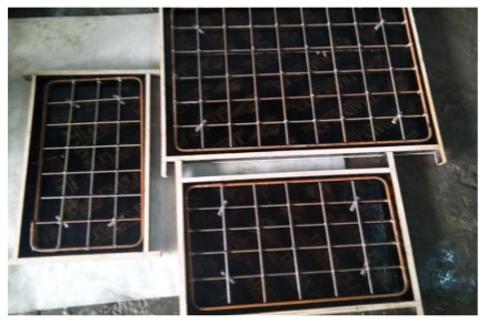
The reinforcing mesh consists of 6 mm diameter deformed bars placed in a single layer at the mid thickness of the wall panels. Three different bar spacings are set in this study, 50, 80, and 100 mm c/c, along both the directions according to ACI 318-14 [15] with a clear side cover of 10 mm. In addition, an 8mm diameter steel reinforcement bar is placed around the wall to strengthen and protect the wall's edges. reinforcement characteristics are shown in Table 9 and Fig. (2).
Probation of steel was carried out at Mustansiriyah University, College of Engineering in Materials Laboratory by using the testing machine SANS 1000 kN, which was calibrated by the “Iraqi Central Organization for Standardization and Quality Control”. Test results indicate that the adopted bars were in accordance with the Standard Specification for steel reinforcement ASTM A615-86 [16] and ASTM A82-05 [17] as shown in Table 10.
| Sieve Size, mm | % Passing | Limits of Iraqi Standard IQS 45-1984 |
|---|---|---|
| 14 | 100 | 100 |
| 10 | 94.47 | 85-100 |
| 5 | 1.66 | 0-25 |
| 2.36 | 0.0 | 0-5 |
| Physical Properties | Test Result | Limits of Iraqi Standard IQS No.45-1984 |
|---|---|---|
| Density (kg/m3) | 2252 | ---- |
| Absorption, percent | 0.92 | ---- |
| Sulfate content, percent | 0.081 | 0.1 percent maximum |
| Size of Sieve, mm | % Passing | Limits of Iraqi Standard IQS 45-1984, Zone 2 |
|---|---|---|
| 10 | 100 | 100 |
| 4.75 | 99.65 | 90-100 |
| 2.36 | 92.32 | 75-100 |
| 1.18 | 64.15 | 55-90 |
| 0.6 | 45.19 | 35-59 |
| 0.3 | 26.78 | 8-30 |
| 0.15 | 3.11 | 0-10 |
| Physical Properties | Test Result | Limits of Iraqi Standard IQS No.45-1984 |
|---|---|---|
| Density (kg/m3) | 2388 | ---- |
| Absorption, percent | 1.1 | ---- |
| Fineness modulus | 2.69 | ---- |
| Sulfate content, percent | 0.31 | 0.5 percent maximum |
|
Nominal Diameter |
Bar Type | Yield Stress (MPa) | Ultimate Stress (MPa) |
Modules of Elasticity (GPa) |
Elongation % |
Variation of Diameter% |
|---|---|---|---|---|---|---|
| 6 | Deformed | 721 | 968 | 200 | ----- | 0.4 |
| 8 | Deformed | 505 | 788 | 200 | 10.3 | ----- |
| Nominal Diameter |
Bar Type | Yield Stress (MPa) | Ultimate Stress (MPa) | Elongation% (ASTM A615-86) | Variation of Diameter % (ASTM A82) |
|---|---|---|---|---|---|
| 6 | Deformed | 400 | 600 | ----- | 0.3 |
| 8 | Deformed | 400 | 600 | 9 | ----- |
3.6. High Range Water Reducing Admixture
The third generation of Geopolymer-based superplasticizer type (F), designed for the production of UHPC, is used (Glenium 51). The Physical properties of glenium 51 is shown in Table 11.
| Physical Properties | Test Result |
|---|---|
| Relative density | 1.1 @ 20 °C |
| Form | Viscous Liquid |
| Color | Light Brown |
| PH | 6.6 |
| Dosage | (0.5-1.6) L/100 kg of Cement |
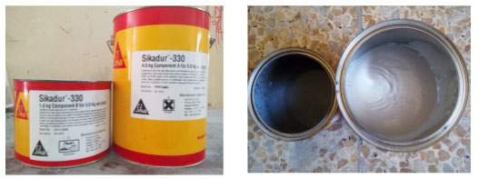
3.7. Sikadur-330 (Epoxy resin)
Sikadur-330 (Epoxy resin) is used in order to avoid any gap between the tested specimen and the steel frame. An epoxy (Sikadur-330) resin is filled inside this gap around the specimen for (7) days for the curing of epoxy to brace (control) the fixity of the wall at supports (Fig. 3).
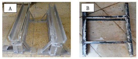
3.8. Configuration of the Test Equipment
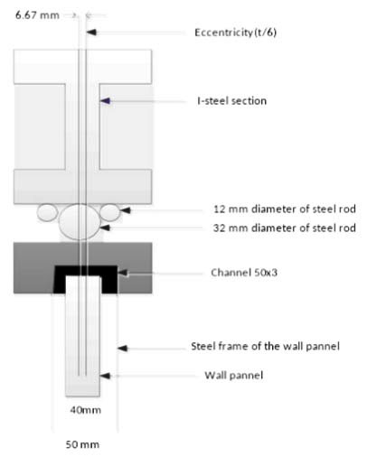
Based on the previous research using test platforms, it has been observed that the preferable test platform for this study was the one used by Ganesan et al. (2013) [18] with some adjustments for lateral restraints in order to make a simple, economical and functional test platform (support simulation). The upper and lower fixed support conditions are simulated by joining a 32 mm diameter high strength steel rod to a channel of size C50 mm × 3 kg / m and welding very well as shown in Fig. (4). The steel bar must be eccentric t/6. The vertical sides are supported by channels 5 cm deep, 2.5 wide and 5 mm thick. Properties of plates as shown in Table 12; Test results indicate that the plates were in accordance with the Standard Specification for ASTM A36 [13] as shown in Table 13. Rectangular steel straps (2.3cm wide and (35cm, 80cm, 30cm) long) are welded at an equidistant space along the channel to have interrelated lateral supports. This operation is carried out with great care and with high precision to guarantee that no spaces are allowed between the support and the welding. To meet the eccentricity when the load is applied, the details of the support are shown in Fig. (5). The two sections in I are fixed tightly to the test machine up and down with many clamps followed by filling the space between the wall panels and the side supports with the epoxy and placing the samples in the laboratory for seven days for epoxy curing.
| Sample | Yield Tensile Strength(MPa) | Ultimate Tensile Strength(MPa) |
Elongation % in 50 mm |
|---|---|---|---|
| 5mm | 285 | 453 | 27 |
| 3mm | 303 | 481 | 26 |
| Grade |
Elongation % in 50 mm |
Tensile Strength(MPa) | Min Yield Tensile Strength(MPa) |
|---|---|---|---|
| A36 | 23 | 400-550 | 250 |
3.9. Test Machine
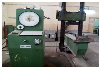
All the walls are tested using a universal test machine that has a capacity of 3000 kN, as shown in Fig. (6). The load is applied progressively in increments of 10 kN until failure. The cracking load is recorded as the load at which the first crack is detected.
4. CONCRETE MIX
Initially, many geopolymer concrete test mixtures are manufactured. The test mixtures are prepared in order to obtain a mixture with good consistency and viability and to understand the basic nature of the mixture. Mix Proportion for GPC based on the mix studied by Basil et al. (2015) [19] with some improvement is involved. as shown in Table 14.
| Metakaolin (kg/m3) | Sand (kg/m3) | Gravel (kg/m3) | Alkaline* Solution (lit/m3) | Water* (kg/m3) |
Iron Filings* (kg/m3) |
Sp** % |
|---|---|---|---|---|---|---|
| 400 | 720 | 1100 | 180 | 40 | 0.5 | 3 |
5. MECHANICAL PROPERTIES OF HARDENED CONCRETE
The mechanical properties of the used geopolymer concrete mixes are listed in Table 15. The compressive strength test is carried out on three cubes of 100х100х100mm according to B.S. 1881, part 116 [20]. Flexural strength (modulus of rupture) test is carried out on a prism of 100x100x500mm according to ASTM C 78-02 [21]. The indirect tensile strength (splitting tensile strength) test is carried out on a cylinder of 100х200mm according to ASTM C496-04 [22]. While the modulus of the elasticity test is carried out on a cylinder of 150х300mm according to ASTM C496-02 [23].
| Concrete Mix | Compressive Strength (fcu) MPa | Modulus of Rupture (fr) MPa | Splitting Tensile Strength (ft) MPa | Modulus of Elacitisity (Ec) MPa |
|---|---|---|---|---|
| GPC | 26.5 | 3.2 | 3.18 | 19.2 |
6. MIXING PROCEDURE FOR GEOPOLYMER CONCRETE
The mixing procedure has an important effect on the workability and strength of the geopolymer concrete. Many researchers state that the geopolymer concrete can be manufactured by adopting conventional techniques which are used in the manufacture of Portland cement [24, 25].
The aggregates are prepared on a saturated surface in the dry state, SSD. The recycled concrete aggregates are first mixed together in dry form in a bucket mixer for three minutes and then metakaolin is added and mixed for two minutes. An alkaline liquid is added to the geopolymer concrete mix and 65% superplasticizer is mixed with additional water for not less than two minutes and is gradually added to the dry materials in the mixer tray for five minutes. After that, iron filling and 35% of superplasticizer were added and mixed for two minutes. The concrete is then compacted with a vibrating table. It is a fact that compaction requires a lot of skill.
7. CURING OF SAMPLES
The specimen is placed under direct sunlight outside the laboratory after demolding. Models are poured at a temperature ranging between 27°C and 30°C and placed under the ambient temperature according to previous research [26].
8. WALL PANELS TESTING PROCEDURE
Before 28 days of the test, all models are cleaned and painted white to ensure that the crack pattern can be easily observed on the wall surfaces and to obtain clear visibility of the cracks during the test. After the test equipment have been prepared, the panel is fixed at the top and bottom brackets; the wall panels are labeled and placed precisely along the edges of the brackets. The panels are levelled to ensure perpendicularity of the panels. The axial load is applied at the eccentricity of t/6 from the center of the samples and the quadrant meters are placed in the middle center of the wall panels. During the test, the applied loads and the corresponding deflections of the middle section are recorded using a dial gauge having a sensitivity of 0.01 mm and a capacity of 25 mm located on the face of the wall panels.
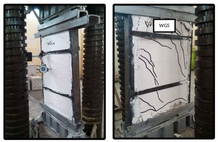
The cracking loads, the maximum axial load with its corresponding deflections in the center of the wall and the reading of the maximum crack width are observed and recorded during the test. Fig. (7) shows the panels before and after the test
9. FIRST CRACK LOAD AND ULTIMATE LOAD
Tables 16 and 17 show the first crack load and ultimate load values for the specimens under two way in-plane loading. The first crack load is taken as the load corresponding to the point at which the load-deflection curve becomes nonlinear.
| Designation | Aspect Ratio (H/L) | First Crack Load (Pcr), kN | Ultimate Load (Pu), kN | Deflection at Cracking Load (∆cr), mm |
|---|---|---|---|---|
| WG1 | 1.875 | 35 | 225 | 13.25 |
| WG2 | 1.5 | 40 | 260 | 9.75 |
| WG3 | 0.75 | 65 | 605 | 6.65 |
The ultimate strength of the wall panel increases with a decrease in the aspect ratio. Table 16 shows that a decrease in the aspect ratio from 1.875 to 0.75 results in an increase in the percentages of the ultimate load by 16% and 63% respectively, leading to an increase in cracking loads by 14% and 86%. The lateral deflections also decrease by 26% and 50%, respectively.
Table 17 shows that the increase in steel reinforcement ratios from 2.32 to 3.38% results in an increase in the percentage of ultimate load by 6%, and 48%, as well as an increase in cracking loads by 11%, and 63%, while lateral deflection decreased by 2% and 20%.
| Designation | Steel Reinforcement Ratio | First Crack Load (Pcr) in kN | Ultimate Load (Pu) in kN | Deflection at Cracking Load (∆cr) mm |
|---|---|---|---|---|
| WG4 | 0.0232 | 36 | 245 | 9.9 |
| WG2 | 0.0267 | 40 | 260 | 9.75 |
| WG5 | 0.0338 | 58.5 | 362.5 | 7.9 |
10. LOAD - DEFLECTION BEHAVIOR
Based on the observations, the load-deflection behavior of the specimens is shown in Figs. (8 and 9).
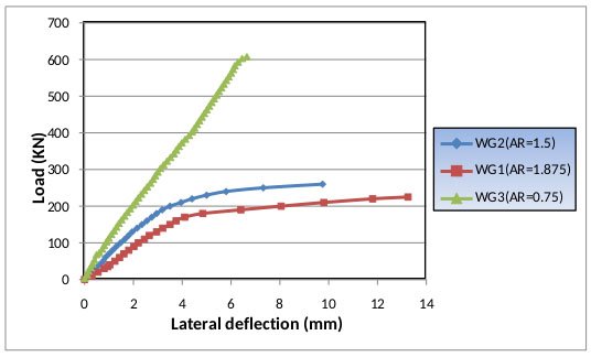
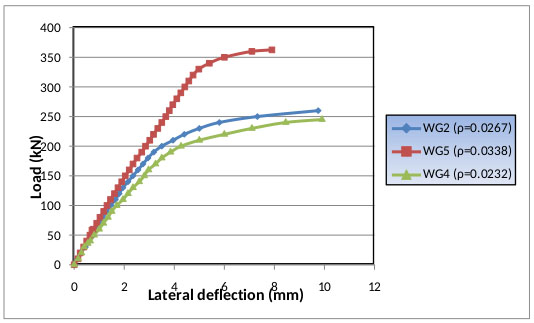
Fig. (8) shows that the lateral deflection increases with the increase in the aspect ratio under two ways in-plane loading. A maximum deflection of 13.25mm is obtained for the ultimate load of 225kN in the case of panel WG1. The maximum deflection values for the panels WG2 and WG3 are 9.75 and 6.65mm, respectively.
Fig. (9) shows that the lateral deflection decreases with the increase in the steel reinforcement ratio under two ways in-plane loading. A maximum lateral deflection of 9.9mm is obtained for the ultimate load of 245 kN in the case of panel WG4. Maximum lateral deflections for the panels WG2 and WG5 are 9.75 and 7.9mm, respectively.
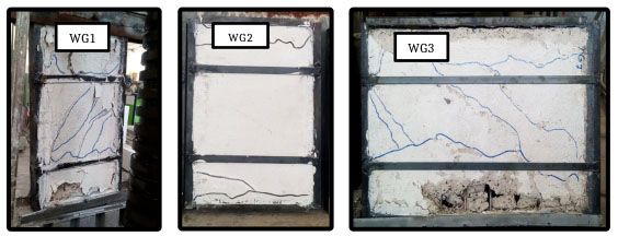
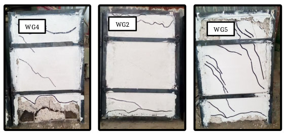
11. CRACK PATTERN
The crack patterns for the tested five wall panels are shown in Figs. (10 and 11).
1. For panels WG1, WG2 and WG3, crush occurrs at the top and bottom of the wall. The horizontal and diagonal cracks in panels WG1, WG2 and WG3 occur at the top and bottom of the walls, while for WG1 and WG3, diagonal cracks appear at the middle of the wall.
2. For the WG2 and WG5 panels, crush occurrs at the top and bottom of the wall while the WG4 panel crushes at the bottom edge. The horizontal and diagonal cracks appear at the top and bottom of the panels WG4, WG2 and WG5 while the diagonal cracks appear at the middle of WG4 and WG5 panels.
CONCLUSION
From the study conducted, it can be observed that:
1. The ultimate strength of the wall panel increases with a decrease in the aspect ratio under two ways in-plane action. The increase in ultimate load is about 63% for the decrease in the aspect ratio from 1.875 to 0.75.
2. The lateral deflection decreases to 50% with a decrease of the aspect ratio to 0.75.
3. The increase in ultimate load capacity is about 48% for an increase in the steel reinforcement ratio from 2.32% to 3.38%.
4. The lateral deflection decreases with the increase in the steel reinforcement ratio to 3.38%.
5. The energy absorption capacity increases with the increase in the percentage of the steel reinforcement ratio. About 50% increase in the energy absorption capacity can be achieved by increasing the steel reinforcement ratio to 3.38%.
6. The increase in the steel reinforcement ratio increases the capacity and deflection resistance.
7. The increase in the steel reinforcement ratio increases the ductile behavior of the wall panels under two-way in-plane loading.
8. Locally manufactured Metakaolin can be used for producing Geopolymer concrete.
9. Geopolymer concrete depending on Metakaolin and the recycled concrete aggregate can be used as lightweight concrete, with density less than 1905 kg/m3 with acceptable resistance.
10. The heat of Geopolymerization process is always less than the heat of hydration of Portland cement. This can be regarded as an advantage for the Metakaolin Geopolymer as compared to Portland cement, especially in hot weather.
11. Using the recycled concrete aggregate is roughly similar to the natural aggregates in the Geopolymer. Therefore, the use of recycled concrete aggregates in the Geopolymer is better because it is economical.
CONSENT FOR PUBLICATION
Not applicable.
FUNDING
None.
CONFLICT OF INTEREST
The authors declare no conflict of interest, financial or otherwise.
ACKNOWLEDGEMENTS
Declared none.

