All published articles of this journal are available on ScienceDirect.
Seismic Fragility of Tall Concrete Wall Structures in Malaysia under Far-Field Earthquakes
Abstract
Introduction:
In recent years, the seismic vulnerability of structures in Malaysia has attracted the attention of researchers mainly because the majority of existing structures have not been designed for seismic actions. In this study, seismic vulnerability of tall concrete wall buildings has been investigated through the development of seismic fragility curves.
Methods:
Two 25-story tall buildings with similar plans but with the different number of parking levels were analyzed through the incremental dynamic analysis. The tall buildings were excited by 15 far-field earthquakes, and their inter-story drift demands and capacities were estimated. Nonlinear response of beams and columns was simulated through the lumped plasticity model. The inelastic response of concrete walls was taken into account through the use of distributed plasticity fibre-based elements.
Results and Conclusion:
The obtained results indicated that the probability of exceeding minor damage to the tall concrete wall buildings located in the Kuala Lumpur city was around 55%. However, the probability of collapse of these structures in the same city was less than 15%.
1. INTRODUCTION
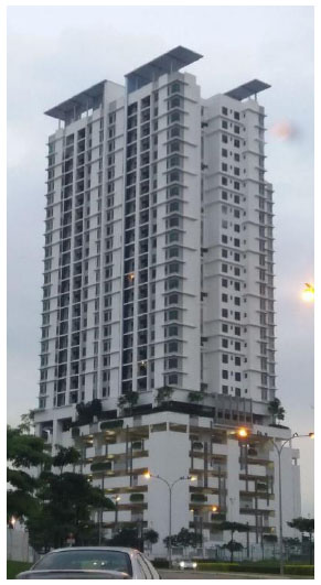
In line with the urbanization and development of the country, the number of tall buildings in Malaysia has been increased rapidly. Tall buildings that have been constructed in major cities in Malaysia ranged from 20 to 50 stories and are used for office or residential purposes. In Malaysia, Reinforced Concrete (RC) is the common material that is used for the construction of tall buildings because of the country’s environmental condition and cost-effectiveness of RC materials. Moreover, concrete walls are the main lateral force resisting system for the majority of tall buildings in Malaysia. As it is shown in Fig. (1), at the lower level of tall buildings, a few stories are used as the parking area. These stories are made by moment-resisting frames so that enough open area is provided for cars to maneuver and park. Above the parking levels, concrete walls are constructed on wide transfer beams. In other words, the majority of concrete walls used in the tall buildings do not continue to the foundation of the structures. Therefore, because of the relatively lower stiffness of parking levels compared to the concrete walls of upper levels, these tall buildings can exhibit a complex dynamic response during a seismic event.
Although some weak earthquakes have been reported within the territory of the country, Malaysia has been shaken mostly by the world’s most active faults that lay in Indonesia and Philippine. During the past decades, Peninsular Malaysia has been hit mostly by the distant-earthquakes from Sumatra subduction zone, while Eastern Malaysia has been subjected to large earthquakes from the Southern Philippines [1]. Light damage to some buildings in Malaysia has also been reported due to the far-field earthquakes, for example the Sumatra earthquakes during 2002 and 2004. Because of its low seismicity, Malaysia received its first national annex for the seismic design of structures in the early 2017. Therefore, many of the existing structures, including tall buildings, have not been designed for seismic actions. The seismic vulnerability of existing tall buildings needs to be evaluated because seismic-induced damage to the tall buildings will give a massive impact on Malaysia’s financial condition and can endanger human life.
Researchers have widely used fragility curves to investigate the vulnerability of different types of structures when subjected to seismic actions [2-4]. Fragility curves are defined as the probability of reaching or exceeding a specific damage level under the earthquake excitation [5]. In general, there are two main methods to develop fragility curves that include empirical [6] or analytical approaches [7]. The empirical method is based on the typological, field survey and expert judgment. This method consumes a lot of time and is costly; however, it shows a realistic picture of seismic vulnerability as it considers all the influential factors, including the site characteristics. The analytical method, on the other hand, uses simulated data in order to extract the seismic fragility curves of structures. Data produced based on the analytical method is less biased because many types of uncertainties can be considered in the analysis. The analytical approach has gained a lot of attention during the past decades and now is a popular method for derivation of fragility curves. For examples, Mwafy [8] used an analytical approach to derived seismic fragility curves of modern high-rise buildings in the UAE. In another study, Yang et al. [9] derived seismic fragility of skewed bridges in the central and southeastern United States. Seismic vulnerability of elevated steel storage tanks supported by reinforced concrete columns was also investigated through an analytical approach by Phan et al. [10].
Previous research on the seismic vulnerability of structures in Malaysia has been limited to concrete box girder bridges [11], low and mid-rise RC buildings [12-16], and industrial structures [17]. Hence, in this study, the seismic vulnerability of tall concrete wall buildings in Malaysia has been investigated through the derivation of fragility curves.
2. METHODS
2.1. Selected Buildings
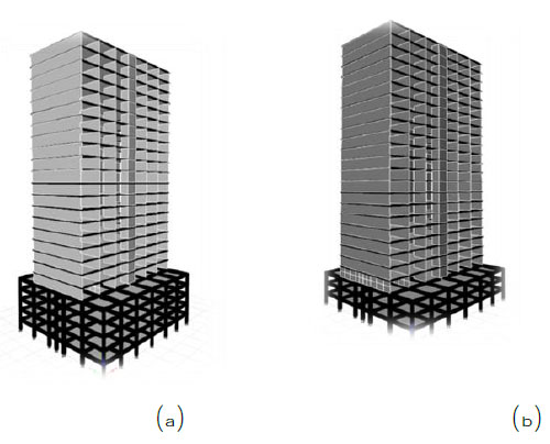
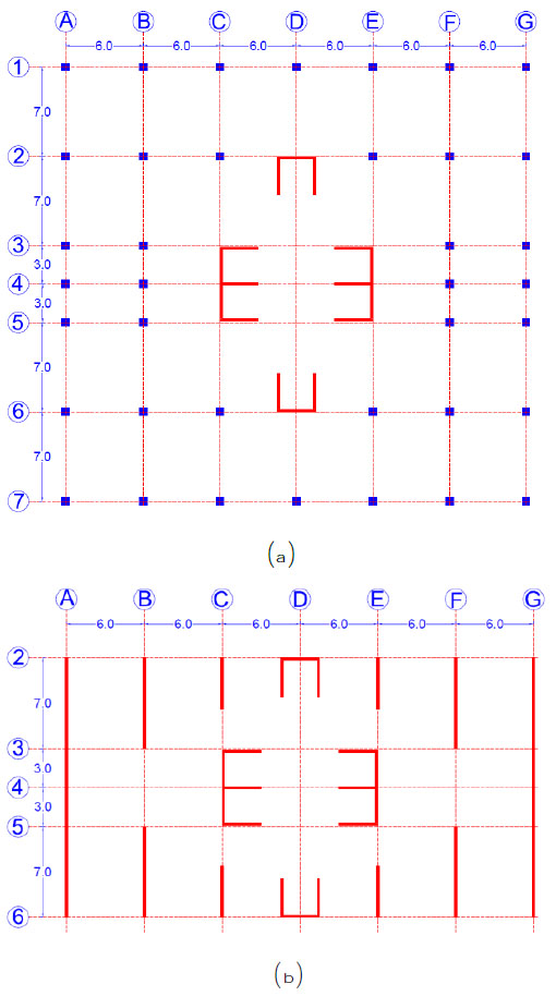
In this study, the seismic vulnerability of two tall buildings was investigated. Both buildings have 25 stories, however, as it is shown in Fig. (2), the first building has five levels for parking area while the second building has three levels for the parking area. As it is shown in Fig. (3), both buildings share a similar plan for the parking levels and residential stories. Besides, in both buildings, a concrete slab with a thickness of 0.17 m covers all the floors. The buildings were designed only for the gravity and wind loads following the standard practice in Malaysia. The live load for residential stories was 2 kN/m2, and for parking levels, it was 5 kN/m2. Moreover, a superimposed load of 1.6 kN/m2 and 1.2 kN/m2 were applied to the residential and parking stories, respectively. The wind load was calculated for a basic wind speed of 33 m/sec and the exposure category B in accordance with the specifications of ASCE 7-10 [18]. The design of structural elements, including beams, columns, and walls, was based on specifications of BS8110 [19] as it is practiced in Malaysia. In the design of structural elements, the compressive strength of concrete was assumed 40 MPa, and the yield strength of reinforcing bars was considered 460 MPa. From the design of structural elements it was obtained that at the upper parking levels, where the concrete walls start, the size of beams was 0.75 m by 0.70 m. On the other floors of parking levels, the size of beams was 0.55 m by 0.50 m. The dimensions of columns in the parking levels varied from 0.70 m by 0.70 m at lower levels to 0.45 m by 0.45 m at upper levels. The concrete walls’ thickness also ranged from 0.15 m at lower levels to 0.10 m at top levels. A reinforcement ratio of 1.2% to 4.4% was obtained for columns. For concrete walls, the longitudinal reinforcement ratios varied from 0.56% at lower levels to 0.25% at upper levels. A minimum transverse reinforcement ratio of 0.25% was sufficient for all concrete shear walls.
2.2. Finite Element Simulation
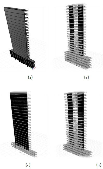
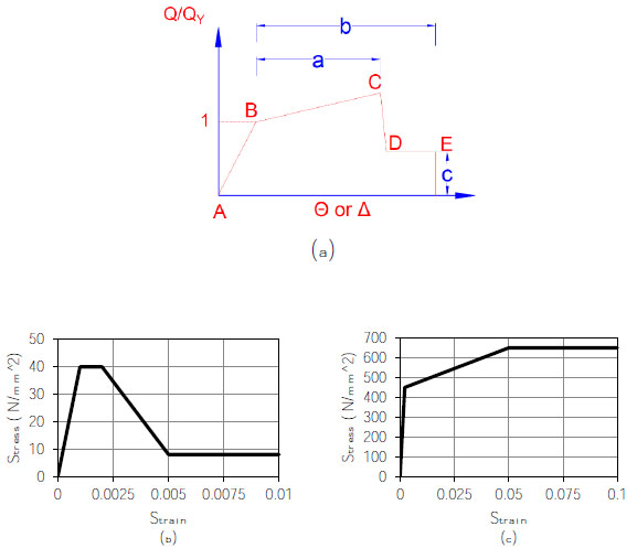
Since the nonlinear analysis of 3-dimensioanl tall buildings is computationally time- consuming, a two-dimensional idealization is often adopted to develop the fragility relationships [8]. Therefore, in this study, the framing systems located on axis A and B were selected for derivation of fragility curves. The finite element models of the idealized framing systems are shown in Fig. (4). As can be seen from the figure, the idealized systems include the beam and columns of parking levels together with concrete slabs and shear walls. It should be mentioned that the vertical stiffness of concrete slabs in the idealized models was calculated on the basis of the elastic stiffness in the 3-dimensioanl models. Finite element models were established in CSI ETABS software program [20]. Nonlinear behavior of beams and columns were simulated through the lumped plastic hinge model [21]. Plastic hinges were assigned to both ends of beams and columns. As it is shown in Fig. (5a) the moment-rotation relationships of plastic hinges together with their limit states were established on the basis of the specifications of ASCE 41 [22]. Nonlinear behavior of concrete walls was simulated using the distributed plasticity fiber based elements [23]. The stress-strain relationships of concrete and reinforcing bars are shown in Figs. (5b) and (5c), respectively. It should be mentioned that since the shear capacity of concrete walls was significantly larger than the seismic demand, it was simulated as an elastic response.
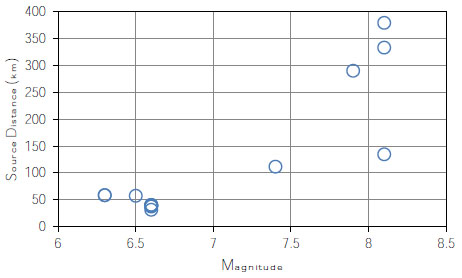
For the derivation of seismic fragility curves, the Incremental Dynamic Analysis (IDA) was used [24]. A 0.75% stiffness-proportional Damping was used in the dynamic analysis [8]. The hysteretic damping was accounted for in the fiber formulation of the inelastic frame elements. Considering the seismic hazard scenario of Malaysia, which is mainly affected by distant earthquakes, totally 15 far-field natural earthquake records were selected for the dynamic analysis. As it is shown in Fig. (6), the source-to-site distance of selected earthquake records ranges from 40 km to 379 km with a magnitude that ranges from 6.3 to 8.1. Table 1 provides more detail for the selected earthquake records.
Following the recommendation of ASCE 41 [22], three structural damage states were used in this study. Immediate Occupancy (IO) that represents minor damage, Life Safety (LS) that represents significant damage without collapse and Collapse Prevention (CP) in which the structure supports the gravity load but with no margin against collapse. The acceptance criteria for the above-mentioned damage states in concrete and reinforcing bars are shown in Table 2 [7]. The acceptance criteria for the damage states of plastic hinges followed the recommended values in ASCE 41 [22].
| Earthquake | Date | Mag. | Site | Comp. Dir. | PGA (g) |
|---|---|---|---|---|---|
| Long Beach. Calif. | 03/10/33 | 6.3 | Subway Terminal, L.A. | N51W | 0.097 |
| Long Beach. Calif. | 03/10/33 | 6.3 | Subway Terminal, L.A. | N39E | 0.064 |
| Lower Calif. | 12/30/34 | 6.5 | E1 Centro | S00W | 0.160 |
| Near E. Coast of Honshu, Japan | 05/16/68 | 7.9 | Muroran Harbor | N00E | 0.226 |
| San Fernando, Calif. | 02/09/71 | 6.6 | 2500 Wilshire Blvd., L.A. | N61W | 0.101 |
| San Fernando, Calif. | 02/09/71 | 6.6 | 3550 Wilshire Blvd., L.A | S00W | 0.132 |
| San Fernando, Calif. | 02/09/71 | 6.6 | 222 Figueroa St., L.A. | S37W | 0.129 |
| San Fernando, Calif. | 02/09/71 | 6.6 | 3470 Wilshire Blvd., L.A | S90W | 0.114 |
| San Fernando, Calif. | 02/09/71 | 6.6 | 4680 Wilshire Blvd., L.A. | N l 5E | 0.117 |
| San Fernando, Calif. | 02/09/71 | 6.6 | 445 Figueroa St., L.A | S38W | 0.119 |
| San Fernando, Calif. | 02/09/71 | 6.6 | Hollywood Storage L.A. | S00W | 0.106 |
| Near E. Coast of Honshu, Japan | 06/17/73 | 7.4 | Kushiro Central Wharf | N00E | 0.205 |
| Michoacan, Mexico | 09/19/85 | 8.1 | Zihuatenejo, Guerrero Array | S00E | 0.103 |
| Michoacan, Mexico | 09/19/85 | 8.1 | Teacalco, Guerrero Array | N00E | 0.052 |
| Michoacan, Mexico | 09/19/85 | 8.1 | Mesa Vibradora C.U., Mexico City | N90W | 0.052 |
| Damage State | Strain in Concrete | Strain in Reinforcement |
|---|---|---|
| IO | 0.002 | 0.01 |
| LS | 0.003 | 0.025 |
| CP | 0.005 | 0.05 |
3. RESULTS AND DISCUSSION
3.1. Derivation of Seismic Fragility Curves
For the derivation of fragility curves the following equations were used [25]:
 |
(1) |
 |
(2) |
 |
(3) |
Where, P(DS|SI) is the conditional probability of exceeding the Damage State (DS) for the given seismic intensity (SI). π is the standard normal distribution; γC is the natural logarithm of the median of drift capacity for a particular damage state; γD|SI is the natural logarithm of calculated median demand drift given the seismic intensity from the best fit power law line. S2 is the standard error and Cov. is the coefficient of variation of the calculated limit State Capacities. ηD|SI stands for the demand uncertainty, while ηC and ηM reflect uncertainties related to the calculation of capacity and modelling errors, respectively. Following previous researches [8] the value of ηM was taken as 0.3.
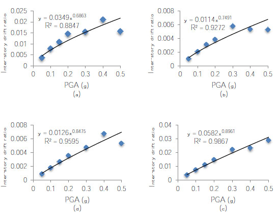
The obtained median inter-story drift capacities from IDA have been summarized in Table 3. It should be mentioned that IDA results indicated that there was a minimal margin between IO and CP limit states in the investigated frames. Therefore, as it can be seen from Table 3, no inter-story drift capacity was found for LS limit state. This is mainly because the structural elements were not designed and detailed for seismic actions. It can also be seen from the table that, regardless of the number of parking levels, the frames located at axis “A” have significantly larger drift capacities when compared with those located at axis “B”. Moreover, the increase in the number of parking levels has increased the CP drift capacity of the frame located at axis “A” and has decreased it for the frame located at axis “B”. It should be also mentioned that ASCE 41 [22] recommends 0.5%, 1%, and 2% of Inter-story Drift Ratios (IDRs) as the limit states for IO, LS and CP drift capacities. Therefore, the frames located at axis “B” have exhibited significantly smaller drift capacities for IO and CP limit states when compared with the recommended values by ASCE 41. The relationship between the median drift demand and peak ground acceleration (PGA) of investigated frame systems have been shown in Fig. (7). An excellent correlation can be seen between the PGAs and the median drift capacities of all frames. Therefore, for the derivation of seismic fragility curves, the PGA of ground motions was considered as the engineering demand parameter for the derivation of seismic fragility curves.
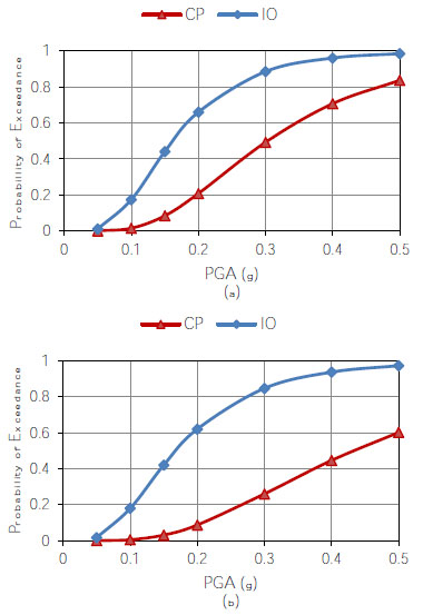
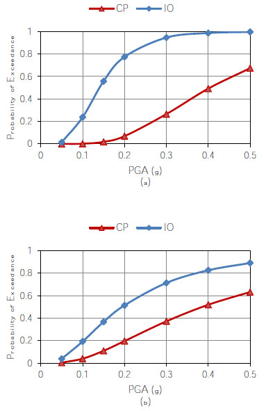
The obtained seismic fragility curves for the frame with 3 and 5 levels of parking are depicted, respectively, in Fig. (8), and Fig. (9). It can be seen from Fig. (8) that the probability of exceeding the IO damage state for the frames located at axis “A” and “B” is almost similar. However, the probability of exceeding CP damage state for the frames located at axis “A” is significantly larger than the frame located at axis “B”. As can be seen from Fig. (9), for the building with 5 levels of parking the probability of exceeding the IO damage state for the frame located at axis “A” is larger than that of axis “B”. However, for small PGAs, the probability of exceeding the CP damage state in the frame located at axis “A” is smaller than the frame located at axis “B”. For large PGAs both frame exhibit almost similar probability of exceeding the CP damage state.
| Frames with 3 Levels pf Parking | Frames with 5 Levels of Parking | ||||||
|---|---|---|---|---|---|---|---|
| Axis “A” | Axis “B” | Axis “A” | Axis “B” | ||||
| IO (%) | CP (%) | IO (%) | CP (%) | IO (%) | CP (%) | IO (%) | CP (%) |
| 1 | 1.54 | 0.3 | 0.61 | 1 | 2.58 | 0.3 | 0.5 |
Comparison between Fig. (8) and Fig. (9) shows that an increase in the number of parking levels increases the probability of exceeding the IO damage state in the frame located at axis “A” and decrease the probability of exceeding the IO damage state in the frame located in axis “B”. On the other hand, the increase in the number of parking levels decreases the probability of exceeding the CP damage state in the frame located at axis “A” and show an insignificant effect on the probability of exceeding the CP damage state in the frame located in axis “B”.
The maximum PGA of Kuala Lumpur city where the majority of tall concrete wall buildings have been constructed in Malaysia is 0.09g [26] on bedrock. Considering the soil effect, the PGA can reach 0.15g. Therefore, by using the obtained seismic fragility curves the maximum probability of exceeding the IO and CP damage states are 55% and 11%, respectively. This means that only repairable damage can be expected for the tall concrete wall buildings in Kula Lumpur. It can also be seen that the tall concrete wall buildings that have lesser parking levels exhibit a smaller probability of exceeding IO damage states for the exterior frames and a higher probability of exceeding IO damage states for the interior frames.
CONCLUSION
This study focused on the development of seismic fragility curves for tall concrete wall buildings in Malaysia. Two 25-story tall buildings with a similar plan but with a different number of parking levels were designed for gravity and wind loads. Then, a two-dimensional idealization was adopted to develop the fragility relationships of the buildings. For this purpose, an exterior and interior framing systems were selected from the designed buildings and fragility curves were derived for these frames. Inter-story drift capacities and demands were estimated using incremental dynamic analysis. Results indicated that for the Kuala Lumpur city where the majority of tall concrete wall buildings have been constructed the probability of exceeding the minor damage state was around 55%. However, the probability of exceeding severe damage state was around 11%. It was also found that buildings with a higher number of parking levels have a higher probability of exceeding the minor damage in their exterior frames and a lower probability of exceeding the minor damage in their interior frames.
CONSENT FOR PUBLICATION
Not applicable.
AVAILABILITY OF DATA AND MATERIALS
The data that support the findings of this study are available from the corresponding author (M.V.) on request.
FUNDING
This study was funded by the Ministry of Higher Education of Malaysia through the RUG votes of 17H80 and 19H36.
CONFLICT OF INTEREST
The authors declare no conflict of interest, financial or otherwise.
ACKNOWLEDGEMENTS
Authors would like to thank Universiti Teknologi Malaysia for their support.


