All published articles of this journal are available on ScienceDirect.
Analytical and Experimental Investigation on Slip-in Gusset Plate Connection for Double C-channel Sections of Cold-formed Steel
Abstract
Background:
Beam-column connections are one of the most important parts of each building, which influence local/global behaviour of structures under vertical and lateral loads. From a practical point of view, a desirable connection is one that can be implemented conveniently in the construction site. For this reason, the connection with the gusset plate and bolts is one of the most commonly used connections to join structural members together. The application of this type of connection with cold-formed steels has not gotten enough attention in the literature and needs more investigation.
Objective:
The objective of this study is to evaluate the behaviour of the gusset plate connection with cold-formed steel sections based on its moment-rotation relation obtained experimentally when the beam depth is varied.
Methods:
Three specimens were built with three different depth of beams (i.e. 200, 250, and 300 mm) and constant depth of column (i.e. 300 mm). A same size gusset plate with a thickness of 10 mm was used for all the connections. A Full-Scale Isolated Joint test (FSIJ) was conducted as a testing method in this study to investigate the behaviour of the connection.
Results:
Three distinct modes of failure were distinguished based on observations in the experiments. Moreover, the obtained results implied that there is a meaningful difference between experimental and analytical results for moment capacity and rotational stiffness of the tested connections. Likewise, the results showed that the beam depth in this joint should be limited to have a ductile connection when the column depth is constant.
Conclusion:
The moment capacity of the tested connections was analytically underestimated by Eurocode 3 relative to the experimental results with an average amount of 75%, while the connection rotational stiffness overestimated by the analytical results with an average of 74%.
1. INTRODUCTION
Nowadays, cold-formed steel is increasingly utilized in building construction, especially for residential buildings [1]. In terms of flexibility and being lighter, cold-formed steel has more advantages relative to other materials such as timber and concrete. Furthermore, recycling potentiality, forming different cross-sections, and easy manufacturing are other benefits of using this material [2]. Likewise, the proper mechanical properties of cold-formed steel (e.g. high strength, stiffness, and resistance to ambient temperature) make this material more appealing for construction (Yu and LaBoube, 2010). In many different aspects, the application of this material has been considerably investigated in recent years. In terms of the seismic performance of structures, the cold-formed steel sections have been gained much attention from the researchers over the last decade [3-6]. In terms of the section configurations and shape varieties of cold-formed steel and their possible various functions, numerous valuable results of the conducted studies are available in the relevant literature [7-12]. Beyond the structural application of this material in the building industry, the cold-formed steel sections have been commonly using as rack structures for the purpose of stocking, which is one of the topics of interest to the researchers [13, 14].
Beam-column connections are one of the most important parts of each building, which influence local/global behaviour of structures under vertical and lateral loads. Failure in the connections may lead to disassembly of beams and columns in a sequential manner and then a progressive collapse of a whole building [15]. A big portion of the investigations about the cold-formed steel structures belongs to the connections of structural members, which shows the importance of this topic [16-22]. From a practical point of view, a desirable connection is one that can be implemented conveniently in the construction site. For this reason, the connection with the gusset plate and bolts is one of the most commonly used connections to join structural members together [23]. Gusset plates in the connections have two key functions: 1) to increase the capacity of connections, and 2) to facilitate the transferring of loads from beam to column.
A beam-to-column connection was studied by Tan [24], which made up of beam and column with cold-formed steel sections, and a hot-rolled steel gusset plate with 6 mm thickness. To form beam and column members, two cold-formed lipped channel sections were placed back to back. In this study, three different depth of beams (i.e. 150, 200, and 250 mm) were used in the tests to investigate the effect of beam depth on the proposed connection. Based on the experimental results, the ratios of joint moment resistance to beam moment resistance were increased in the range of 0.25 to 0.75 by using a higher depth of beams. Moreover, getting connection ductility more than 30 mRad showed that the connection was a ductile connection. Based on the obtained results, ultimately, it was concluded that the proposed connection can be classified as a partial strength connection. In this study, following Tan’s investigation [24], the same connection was experimentally studied with a thicker gusset plate (t=10 mm) in similar circumstances. Three connection specimens with different beam depth and constant column depth were prepared and tested to provide the moment-rotation relation of the connection. The connections were evaluated based on important characteristics, such as moment resistances and rotational stiffnesses obtained experimentally. Corresponding analytical results of each specimen were computed and provided for verification purposes.
2. ANALYTICAL STUDY
The moment-rotation relation of a connection can be developed by using the analytical method, which is useful to determine characteristics of the connection: i.e. rotational stiffness and moment resistance. In this study, the experimental moment-rotation relations are validated by theoretical results. For this purpose, two important characteristics of connections, i.e. the moment resistance (Mj) and rotational stiffness (Sj), are theoretically calculated here and then presented in the figures of Section 4.1 in order to have a datum for comparison work. To determine the moment resistance of the connections, the buckling moment of gusset plate (Mb,Rd) and bolt-group moment of gusset plate (Mjg2) were computed and the minimum value of them selected for the theoretical moment resistance of the connection (Mj). The rotational stiffness of the joint (Sj) depends to the stiffness of the gusset plate that it can be calculated based on three initial stiffness namely, stiffness of bolt group on the beam (Sb,bg,ini), stiffness of bolt group on the column (Sc,bg,ini), and initial stiffness of gusset plate (Sgp,ini). The calculation of Mj and Sj is briefly presented below:
To calculate bolt-group moment of gusset plate, the shear capacity of bolts Fv,Rd can be calculated by Eq. (1), based on BS EN 1993-1-8:2005 [25]. M12 bolts grade 8.8 was used in connection, so (áv = 0.6, ultimate yield strength of bolts (fub) = 800 MPa, cross section of bolts (Asb) = 84.3 mm2, and partial factor (yM2) =1.
 |
(1) |
The moment resistance of the bolts group in the gusset plate depends on the bolt’s reaction (ΣFi) and lever arm (Li) (Eq. 2).
 |
(2) |
The buckling moment of gusset plate (Mb, Rd) is calculated by Eq. 3 and influenced by the reduction factor for lateral-torsional buckling (XLT), effective cross-section (Wy), yield strength of bolts (fyb) = 640 MPa partial factor (γM0) = 1.
 |
(3) |
Refer to BS EN 1993-1-1:2005 [26], the reduction factor (XLT) can be determined by Eq.(4).
 |
(4) |
Where (λLT) is non-dimensional slenderness factor, and (ΦLT) is lateral-torsional buckling. The needed parameters in Eq. (4) are determined by Eqs. (5-7), based on BS EN 1993-1-8:2005 [25].
 |
(5) |
 |
(6) |
 |
(7) |
Where λLT is imperfection factor for lateral-torsional buckling, fy is yield strength of plate, Mcr is moment capacity, Ieff is effective inertia moment of cross-section, and hw is depth of the web.
To calculate the rotational stiffness of joint (Sj), three properties should be calculated; stiffness of bolt group on the beam (Sb,bg,ini), stiffness of bolt group on the column (Sc,bg,ini), and initial stiffness of gusset plate (Sgp,ini). The Sb,bg,ini and Sc,bg,ini can be determined by Eq. (8):
 |
(8) |
Where: E= elastic modulus, z= lever arm, k=stiffness of springs.
T-shape gusset plate connection was studied in an investigation by Bucmys [27]. He derived a formula for the stiffness of the T-shape gusset plate as Eq. (9). This equation can be applied for a rectangular gusset plate by taking Lb=0. In this case, the simplified equation would be as Eq. (10).
 |
(9) |
 |
(10) |
Where: M1 = bending moment of the column bolts group; M2 = bending moment of the beam bolts group; La= distance from the rotation centre of the beam bolt group to the edge of gusset plate; Lb = distance from the outer bolt centre of the column bolt group to the edge of gusset plate; Lc = distance between outer bolts of the column bolt group; I1 = the moment of inertia of the beam outstand element; I2 = the moment of inertia of the column outstand element; V = shear force due to the beam load.
The total stiffness of the gusset plate can be obtained by Eq. (11).
 |
(11) |
Lastly, the rotational stiffness of the connection (Sj) can be derived by Eq. (12), based on BS EN 1993-1-8:2005 [25].
 |
(12) |
Where: Sj,ini is the initial rotational stiffness of connection, η is the stiffness factor, θ is the rotation of joint, and Mj is the moment resistance of the joint.
Table 1 highlights the values for the moments resistance (Mj) and rotational stiffness (Sj) of the connection calculated in this section analytically. The presented values have been used in the figures of moment-rotation relationships as theoretical criteria in Section 4.1.
The moment-rotation relation of a connection can be obtained from experiments as well. The moment of the joint (Mj,exp) is calculated by multiplying the applied point load to the lever arm that is the distance from the point load to the front flange of the column. The rotation of the connection (φj,exp) is determined by subtracting two numbers measured by inclinometer devices installed in appropriate places on the webs of the beam and column. This method was used and explained in the next sections to provide the moment-rotation relation of connections.
| Test Label |
Mb,Rd kNm |
Mjg,2 kNm |
Mj (The) kNm |
Sb,bg,ini kNm/rad |
Sc,bg,ini kNm/rad |
Sgp,ini kNm/rad |
Sj (The) kNm/rad |
|---|---|---|---|---|---|---|---|
| BGJ-1 | 21.95 | 20.6 | 20.6 | 816.4 | 816.4 | 15681.2 | 637 |
| BGJ-2 | 33.17 | 22.4 | 22.4 | 1130.5 | 1130.5 | 26342.6 | 892 |
| BGJ-3 | 46.19 | 24 | 24 | 1130.5 | 1130.5 | 42471.7 | 910.2 |
3. MATERIALS AND METHODS
In this study, the cold-formed steel material with a grade of 350 N\mm2 was applied to form double lipped channel C-sections connected back-to-back. The use of double C-sections makes the profile’s cross-section symmetrical and therefore it improves the section in terms of buckling resistance. The length of the columns and beams used in experiments were 300 and 100 cm, respectively. Three profiles for beams (C200, C250, and C300) and one profile for the column (C300) were constructed based on BS EN 1993-1-3:2006 [28]. The dimensions of employed cross-sections are summarized in Table 2.
| Profile | Dimension (mm) | ||||
| Web | Flange | Lip | Thickness | Radius | |
| C20024 | 203 | 76 | 21.0 | 2.4 | 5 |
| C25024 | 254 | 76 | 20.5 | 2.4 | 5 |
| C30024 | 300 | 96 | 27.5 | 2.4 | 5 |
| Labels | Beams | Column | Details of Connections (mm) | Numbers of Bolts | |||||||
| tg | hg | Lg | e1 | e2 | p1 | p2 | p3 | ||||
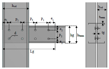
| IJT-BGJ-1 | C20024 | C30024 | 10 | 203 | 600 | 50 | 50 | 200 | 103 | 100 | 8 |
| IJT-BGJ-2 | C25024 | 10 | 254 | 600 | 50 | 50 | 200 | 154 | 100 | 8 | |
| IJT-BGJ-3 | C30024 | 10 | 300 | 600 | 50 | 50 | 200 | 200 | 100 | 8 | |
Fig. (1) shows the configuration of the connection’s bolts employed in three specimens, which arranged according to guidelines in Eurocode 3. All of the applied bolts had the same size and grade as M12 Grade 8.8 placed in 13 mm bolt holes. Grade S275 of hot-rolled steel in rectangular shape was utilized for a gusset plate with a thickness of 10 mm in the connections. Table 3 summarizes the connection details for three specimens.
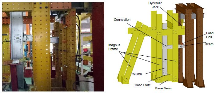
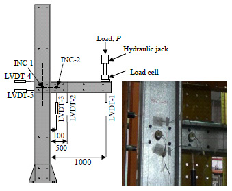
As shown in Fig. (2), full-scale isolated joint (FSIJ) experiments were conducted on the specimens installed in a “MAGNUS” test frame at the structural laboratory of civil engineering school in Universiti Teknologi Malaysia (UTM). The hydraulic jack and load cell were located at the end of each beam, as shown in Fig. (3). Each specimen was loaded gradually and step by step in a range of 0.2-0.5 kN. Lateral restraints were vertically applied to avoid excessive torsion of the beam. Five LVDTs (Variable Linear Differential Transformer) and two inclinometers were used as measurement instrumentations installed on the specimens as shown in Fig. (3). The measured data of LVDTs and inclinometers (i.e. deformations and rotations) were recorded by a data logger and manually, respectively. Likewise, the applied loads were measured by a load cell connected to the data logger. All the specimens were loaded until failure occurred in them.
4. RESULTS AND DISCUSSION
4.1. Modes of Failures
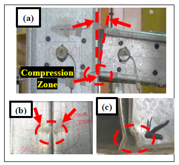
Fig. (4). shows the deformation of specimen IJT-BGJ-1 when the applied load is 27.5 kN. The rotation of the beam relative to the column and also the compression zone in the connection were marked in Fig. (4a). The local buckling in the column and beam are shown in Fig. (4a and 4b), respectively, which occurred due to excessive applied load. In this state of the load, the deformations of the specimen in the vertical plane were the same on both sides of the beam, while no deformation was observed in top view or side view of the connection due to proper performance of vertical restraints in the test setup that prevented the beam and column from any torsions Fig. (4c).
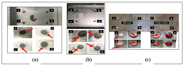
In general, the failure mode of connection specimens occurs progressively since the moment capacity of the beam or column is not able to sustain the applied load [29]. This phenomenon was also observed here in the testing of three specimens. Fig. (5 a-c) show ovalization of the bolts’ holes in the column, beam, and gusset plate of the specimen, respectively. These holes elongation occurs due to the low strength capacity of member’s plates, particularly in cold-formed material. As it is seen in terms of deformation amount, the column has the largest ovalization and followed by the beam and then gusset plate in the same order. For the column, this attributes to higher bearing loads of the column bolts regard to the beam bolts. The gusset plate has the smallest amount of ovalization due to having a thicker web thickness (10 mm) hence it is a less critical element compared to the beam and column.
Three distinct failure modes were distinguished by visual observation during three experiments. These modes were similar for each specimen and they were located in the compression zone and bolts’ holes. The three observed failure modes can be categorized as: 1) bearing failure of bolts’ holes at the column, beam, and gusset plate, 2) local buckling at column flange, and 3) local buckling at bottom flanges of beam.
4.2. Analytical and Experimental Results
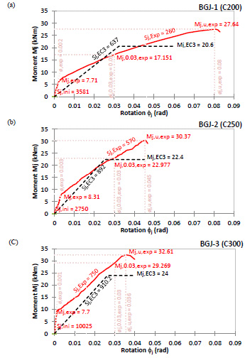
The moment-rotation relation of three specimens was prepared analytically (black dashed line) and experimentally (red line) for each connection, as shown in Fig. (6 a-c). Three parameters (i.e. rotational stiffness, moment resistance, and rotational capacity) are important in the behavior of connections, which were calculated and verified in corresponding points of each curve in the figures. As it is seen, the rotational stiffness of the connections in experimental curves is smaller than the relevant results obtained analytically, while the moment capacities from experiments have a bigger value than the analytical results. Moreover, the ductility of the connection decreases when the depth of the beam increases. Hence, it can be said that the connection ductility is a dependent parameter to the depth of the beams when the depth of the column is constant. In other words, if the beam depth increases more than 30 cm in this study, it tends to rotate below 0.3 rad and therefore the connection could not be considered as a ductile connection.
| (a) | (b) | ||||||||||||
|---|---|---|---|---|---|---|---|---|---|---|---|---|---|
| Test Label | Mj (Exp) kNm | Mj (The) kNm | Mj Ratio | Sj (Exp) kNm/rad | Sj (The) kNm/rad | Sj Ratio | Test Label | Mj (Exp) kNm | Mj(The) kNm | Mj Ratio | Sj (Exp) kNm/rad | Sj (The) kNm/rad | Sj Ratio |
| BGJ-1 | 27.64 | 20.6 | 0.75 | 260 | 637 | 2.45 | T21 | 8.93 | 7.38 | 0.83 | 221 | 253 | 1.14 |
| BGJ-2 | 30.37 | 22.4 | 0.74 | 570 | 892 | 1.56 | T23 | 14.27 | 13.12 | 0.92 | 303 | 470 | 1.55 |
| BGJ-3 | 32.61 | 24 | 0.74 | 750 | 910.2 | 1.21 | T25 | 22.74 | 20.5 | 0.90 | 553 | 744 | 1.35 |
| (a) | (b) | ||||
|---|---|---|---|---|---|
| Comparison Variable | Exp. Result | Tan (2009) | Comparison Variable | Exp. Result | Tan (2009) |
| Thickness of Gusset Plate | 10 mm | 6 mm | Thickness of Gusset Plate | 10 mm | 6 mm |
| Depth of Column | 300 mm | 250 mm | Depth of Column | 300 mm | 250 mm |
| Test Label | IJT-BGJ-1 | T23 | Test Label | IJT-BGJ-2 | T25 |
| Mj(Exp) (kNm) | 27.64 | 14.27 | Mj(Exp) (kNm) | 30.37 | 22.74 |
| Mj(The) (kNm) | 20.6 | 13.12 | Mj(The) (kNm) | 22.4 | 20.5 |
| Sj (Exp) (kNm/rad) | 260 | 245 | Sj (Exp) (kNm/rad) | 570 | 553 |
| Sj (The) (kNm/rad) | 637 | 470 | Sj (The) (kNm/rad) | 892 | 744 |
Referring to the experimental results presented in Fig. (6), the ultimate moments (Mj,u,exp) of connections were increased when a higher depth of beam has been used for the specimens. However, the rate of these increments is almost the same and not more than 10% for each connection. Interestingly, the same rate of increments was determined for the ultimate moments calculated analytically. The amount of initial rotational stiffness (Sj,ini) in the experiments was specified for each connection in Fig. (6). It is seen that the connection with the highest beam depth has got the highest initial rotational stiffness as expected. Regarding the rotational stiffness (Sj) of the tested connections, this characteristic has a growing trend both experimentally and analytically, when the beam depth was raised. The rotation in which the ultimate moment occurs is called the ultimate rotation of the connection. As is seen in Fig. (6), the beams with higher depth possess the lower ultimate rotation (ϕj,u,exp) when the depth of the column is constant.
The experimental and theoretical values of moment capacity and rotational stiffness are summarized for each specimen in Table 4a along with their corresponding ratios. Likewise, the same table is prepared as Table 4b for the results of another study [30] for the comparison purpose. As expected, the moment capacity and the stiffness increase by a higher depth of beam based on the results of two studies. In this study, the average theoretical to experimental ratios for moment capacity and stiffness are 0.74 and 1.74, respectively, while these ratios are 0.88 and 1.35 for the other study in the same order. Therefore, it can be concluded that the moment capacity of the proposed connection is underestimated analytically, in contrary to the rotational stiffness, which is overestimated by Eurocode 3.
Two comparison works in the same circumstances are presented in Table 5a and 5b, between experimental and theoretical results of the current study and Tan’s study. In the two cases, two specimens with the same beam depth were compared together, while they have different column’s depth and gusset-plate’s thickness. These comparisons show that both moment capacity and rotational stiffness of connections increase when the gusset-plate thickness and column’s depth increase, here from 6 to 10 mm, and 250 mm to 300 mm, respectively. Hence, it can be claimed that these two key characteristics of the connection depend on the thickness of the gusset plate and the column depth directly.
CONCLUSION
An analytical and experimental study was successfully conducted on the in-slip gusset-plate connection of c-channels sections with cold-formed steel sections. Based on the results of this study, the following conclusions can be drawn:
(a) Three distinct failure modes on this type of connection were experimentally distinguished: i.e. bearing failure of bolt holes located at columns, beams, and gusset plates; local buckling at column flange in compression zone; and local buckling at bottom flange of the beam in the compression zone.
(b) The moment capacity of the tested connections was analytically underestimated by Eurocode 3 relative to the experimental results with an average amount of 75%, while the connection rotational stiffness overestimated by the analytical results with an average of 74%. Interestingly, these underestimates and overestimates are in correlation with the findings of the other study.
(c) Based on the obtained experimental results, the ductility of the tested connections (rotation capacity) decreases by using higher beam depth when the depth of the column is constant. To have a ductile connection or rotation capacity more than .03 rad, therefore, the depth of beams must have a limitation and to be selected carefully.
(d) Based on the conducted comparison work, the moment capacity and rotational stiffness of the studied connection have a direct relationship with the gusset plates’ thickness and the column’s depth.
CONSENT FOR PUBLICATION
Not Applicable.
AVAILABILITY OF DATA AND MATERIALS
The authors confirm that the data supporting the findings of this study are available within the article.
FUNDING
This research was funded by Sriwijaya University and Construction Research Centre (CRC) in Universiti Teknologi Malaysia (UTM) (grant no. 4B235).
CONFLICT OF INTEREST
The authors declare no conflict of interest, financial or otherwise.
ACKNOWLEDGEMENTS
The authors would like to express their utmost gratitude to their supervisors, Professor Anis Saggaf and Professor Mahmood MD Tahir for their guidance and assistance throughout the study.


