All published articles of this journal are available on ScienceDirect.
Seismic Behaviour of 17th Century Khusro Tomb due to Site-Specific Ground Motion
Abstract
Introduction:
Site Specific time history analysis is performed on a 17th century old Khusro Tomb built-in 1622 A.D. by Sultan Nisar Begum. It is a beautiful example of Mughal architecture.
Methods:
A 3-D finite element model is prepared on Ansys Workbench. Gravity analysis results show the behaviour of Tomb due to its geometry and stress variation is plotted in a form of contour. Modal analysis results show the first three frequencies of Khusro Tomb viz., 21.62, 21.68 and 25.38 Hz. In the absence of earthquake record, the stochastic finite fault model is used to generate synthetic site-specific time history to assess the seismic behaviour of the tomb.
Results and Conclusion:
Time history analysis results show that the Khusro Tomb's geometrical configuration is adequate to withstand the earthquake due to nearest Allahabad fault. The critical elements of the Tomb are highlighted based on analysis that can be effectively used for the maintenance of the Tomb.
1. INTRODUCTION
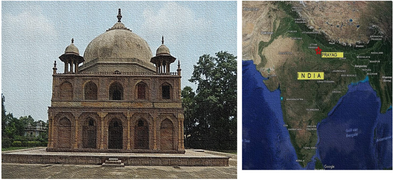
India is a country of rich diversified culture having heritage buildings like temples, churches, the tomb, forts and palaces. It encompasses some of the world's most famous buildings viz., The Taj Mahal, Ancient Churches of Goa, Qutab Minar, Red Fort and The Palaces of Udaipur and Jaipur. The Khusro Tomb, as shown in Fig. (1), is one of the most important archaeological structures of the Prayag City (Previously Allahabad city, Uttar Pradesh, India) constructed by Sultan Nisar Begum (Sister of Amir Khusro), in the memory of Amir Khusro, the eldest son of Jahangir and Shah Begum, in the year 1622 A.D [1,2]. It is a two-storied building with an arcaded wall, surmounted by a large hemispherical dome on an octagonal drum and the small chhatris (a round shape similar to umbrella) on all the corners of the Tomb. The interior of the tomb consists of a single room, whose walls are painted with a design of floral patterns and the dome is a medallion with the star and geometric patterns, is an utmost example of the Mughal Architecture. The Heritage/monumental buildings are necessary to be preserved in order to protect our cultural and social values for future generations and they are the assets for the Nation. In India, Archaeological Survey of India (ASI), Department of Culture, Ministry of Tourism and Culture, is responsible for the archaeological researches and safeguard of the cultural heritage. Hence, requires a detailed numerical model to understand the impact of various forces (static and dynamic loading) on the structure and to know about the critical area for rehabilitation purposes.
Many studies are available on the analysis of historical masonry buildings, including experimental works [3-5], non-linear static (pushover and kinematic limit analysis) and full non-linear dynamic analysis [6] and studies on design choices and selection of most appropriate materials and methods for strengthening [7]. The seismic vulnerability of the old masonry by considering the influence of non-linearity in material property using a finite element model in which the non-linearity of the masonry is considered [8-19]. In all these studies, a proper guideline is given to analyse old monumental structures. But none of these reported the behaviour of the monument for a site-specific simulated ground motion.
In the present work, Finite Element Analysis (FEA) is used to analyse the static and dynamic structural behaviour of Khusro Tomb. Accurate solid models are fundamental in this type of analysis and hence a 3-D model of the Khusro Tomb is made only after the detail survey and measurement of the entire monument and 30% reduced material properties are used to understand the behaviour of the structure. The standard gravity load and modal analysis is performed on the 3D- model. The site-specific ground motion is estimated using a regional seismological parameter in order to simulate ground motion at Allahabad, due to Allahabad fault present at a distance of 70 km, using the stochastic finite fault model based on Boore [20, 21], Motazedian and Atkinson [22] approach. In the present approach, instead of using the different earthquake time history for the region having scare data or no data of earthquake records, one can opt this method for analysing any other structure by simulated site-specific ground motion. The study shows the stress variation, displacement and acceleration response of the Monument and may help the engineers and planners to know the effect on the monument due to nearby faults and helping them to locate the critical point for its proper maintenance and retrofitting work.
2. EARTHQUAKE SCENARIO AROUND ALLAHABAD
The ground shaking of the Himalayan region and peninsular India is due to the incessant subduction of Indian plate beneath the Eurasian plate. The subduction results in the accumulation of sub-surface stresses that releases the energy from time to time [23]. Shukla [24] and Singh [25] disclose the presence of many potential seismic sources that make the regional tectonic quite complex. They also stated that the Indo- Gangatic Plain (IGP) has experienced a large number of earthquakes in the past 100 years, Prayag City lies in IGP, and there is great prospect of a major earthquake in the near future. Prayag (Allahabad) has already been exposed to shakes of many past earthquakes that occurred in Uttar Pradesh e.g., Rae-Barelli, (1925, Mw 6.0), Bulandshahar (1956, Mw 6.2), Gorakhpur (1965, Mw 5.7) and Moradabad (1966, Mw 5.8) earthquakes); countrywide e.g., Dharchulla (1916 Mw 7.5), Uttarakhand (1945, Mw6.5), Uttarkashi (1991, Mw 6.8) and Jabalpur (1997, Mw 6.0)) and earthquakes like Nepal-Bihar (1934, Mw 8.4), 25th April Nepal (2015, Mw 7.8) and May Nepal (2015, Mw 7.3) from the adjoining region. The sources like Main Central Thrust (MCT) and Main Boundary Thrust (MBT) that are very close to Prayag city and are one of the highly earthquake active regions in the world. It has been observed from almost thirty decades that Faizabad Ridge (~70km from Prayag (Allahabad City) is inactive and it is in high stressed due to a large seismic gap and can, therefore, cause a high magnitude earthquake in the near future [26]. Hence in the absence of recorded ground motion, synthetic earthquake has been simulated and discussed in the subsequent section. Therefore, because of the possible seismic gaps and tectonic setup around the region, it is important to understand the seismic response of the monuments like Khusro tomb.
3. ABOUT KHUSRO TOMB AND MODELLING
The Allahabad city shows the imprints of external appearance in the forms of its monuments viz., administrative, residential, educational, and devotional, which were built over a long span of time of the Mughals, the colonial, down to the contemporary. The monuments show the signature of varying practices of the construction and architecture of the different era. The information related to Mughal architecture is very trivial for the Allahabad city. Similarly, during the colonial period, the city prolonged under British rulers and their Indian subordinates then, embellish the city with mansions, monuments or building that reflect the power, glory and pride of the city. During those days many saints and fakirs lived in the city, due to which it is also known as Fakirabad. Apart from its miserable poverty, the city did have a magnificent fort on the bank of river Yamuna, the tombs at Khusrobagh, a garden and a sarai laid by the king Jahangir who ruled and lived in Allahabad from 1599 A.D. to 1609 A.D. In the construction of the buildings, the European traces on the settlements and monuments of Allahabad were observed and the Khusro tomb had the imprints of Europeans architecture.
The place is mentioned both as a bagh and a sarai (originated from the Persian word, means garden). Till 1858 A.D., there was no doubt about its character as the Mughal caravanserai [27]. It is described as follows:
Among the finest structures of Allahabad is called a sarai of Khusro, the illfated son of Jahangir. It is a fine quadrangle surrounded by an embattled wall along the inside of which are a series of lodges for gratuitous reception of travellers. Adjoining is a garden of pleasure ground, some fine mango trees and three mausoleums in a rich, magnificent yet solemn style of architecture. The grandeur of these tombs is once again praised in 1908 when they are described as “plain but massive” and that the “interiors of the principal mausoleum is adorned with painted flowers and birds”. The Khusrobagh was obviously the site of a Mughal garden combined with the caravanserai apart from the three original tombs with one more added later, raised respectively for Khusro, his mother and sister with the fourth one for Tambolan Bee (Tambolan standing for Istanbul in Turkey). It may thus be summed up that European response to the pre-existing architectural monuments, but their greatest admiration was for the Khusro Bagh [27, 28].
3.1. Building Details
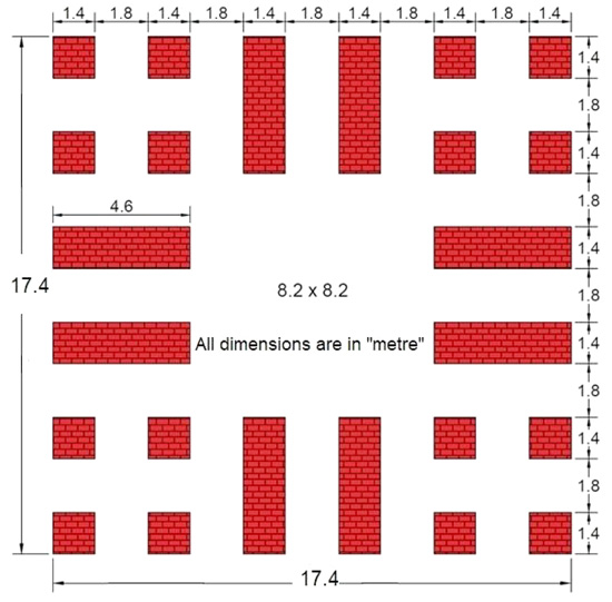
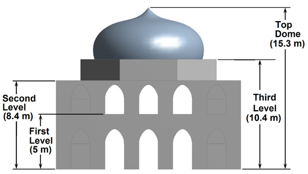
Khusro Tomb is a complex historical structure made up of masonry. Masonry is considered as non-linear elastic material with negligible tensile strength. The behaviour of masonry structures can be reproduced using finite element models with the material properties notwithstanding tension. Figs. (2 and 3) shows four levels of the Khusro Tomb, the first level, second level, third level and top dome with a height of 5.0, 8.4, 10.4 and 15.3 m respectively. On each face, there are five openings of an arch shape. The first one has a central door opens in the room having a square dimension of 8.2m
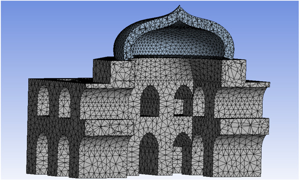
As discussed earlier that the tomb is symmetrical about two planes, i.e., only one-fourth of the structure has to be drawn and replicated to complete the whole structure. Fig. (4) shows the FE meshing details of the Khusro tomb having a total 71839 numbers of solid elements and 8615 surface elements. Altogether 1774 contact elements are used in the model. The model contains two types of elements SOLID187 (10-noded tetrahedral structural solid element) and SURF154 (4 or 8-noded quadrilateral structural surface element). Both the elements have three degrees of freedom at each node. SOLID187 is also capable to solve deformation of nearly incompressible elasto-plastic material and fully incompressible hyper-elastic material. SURF154 is also capable to solve various load and surface applications.
3.2. Element Description
Brick masonry is modelled using SOLID187 element. A three-dimensional 10 nodded tetrahedral element has 3 degrees of freedom at each node (translation in x, y, and z directions). The element has mixed formulation capability for simulation of linearly in compressible elastoplastic materials. The shape functions of the elements are as follows:
N1 = ξ1(2ξ1 - 1), N2 = ξ2(2ξ2 - 1), N3 = ξ3(2ξ3 - 1), N4 = ξ4(2ξ - 1) N5 = ξ1ξ2, N6 = ξ2ξ3, N7 = ξ1ξ3, N8 = ξ1ξ4, N9 = ξ2ξ4, N10 = ξ3ξ4
Displacement is obtained using equations 1.
 |
(1) |
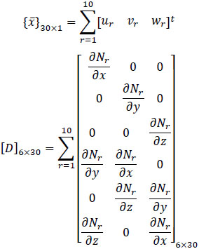
where N1, N2, N3 …. N10 are shape functions and u1, u2, u3 …u10, v1, v2, v3…v10, and w1, w2, w3…w10 are displacement at corresponding nodes. Further, the strain is estimated using the strain-displacement relationship.
 |
(2) |
wher{ϵ}6×1is strain vector
{ϵ}6×1 = [ϵxx ϵxx ϵzz ϵxy ϵyz ϵzx]t
And  is displacement at each node
 |
From obtained values of strain, stress is estimated using stress strain relationship.
 |
(3) |
Where D is the rigidity matrix
 |
and {σ}6×1 is stress vector
{σ}6×1 = [σxx σyy σzz σxy σyz σzx]t
4. MATERIALS AND METHODS
4.1. Properties of Material
After extensive literature review, a book on repair performed on different monuments during 1954-55 describes the work. A small paragraph on repair work of the Khusrobagh Tomb is shown from the book, Indian Archaeology 1954-55, A review which was edited by A. Ghosh [28].
“The tomb of Bibi Tambolan, some important work was carried out, such as the provision of dasa stones with a foundation of lakhauri brick in lime over a lime-concrete bed all-round the platform of the tomb and the replacement by new ones of broken, missing and decayed stones in its stone pavement. The wide joints and cracks in the main arch, the spandrel and the facade on the south side of the southern gateway were grouted, while ordinary joints were treated with recessed lime-pointing. The southern facade together with the bastions of the gate, was re-plastered after the removal of old and decayed plaster. The broker stone lotus over the south east turret of the gate was repaired”.
The paragraph provides some hint of the material used in the Khusrobagh tomb. The Finite element analysis of historical structures largely depends on the accurate estimation of material properties and its utilization in numerical models. Mechanical properties of stones and bricks were investigated by Nuno and Lourence [9] for Gaioleiro buildings in Lisbon, Portugal whereas Michele and Vignoli [10, 11] carried out studies on Romanesque Masonry and Basilica of Sanat Maria. It was difficult to find the engineering properties of the Khusro Tomb due to prohibited access for testing of the material of the structure. Hence, the average value of the material tested assumed by other researcher can be considered the representative of the behaviour of the materials used in Khusro Tomb. Table 1 shows the properties of material assumed for the present study based on the literature survey of the monuments of the same era.
| Masonry Site |
Mass Density ρ (kg/m3) |
Young’s Modulus E (MPa) |
Poisson’s Ratio ν |
|---|---|---|---|
| Gaioleiro buildings Lisbon, Portugal [9] |
1910 | 779 | 0.2 |
| Romanesque masonry Church [10] |
2200 | 2000 | 0.25 |
| Basilica of Santa Maria all’Impruneta, Italy [11] | 1900 | 1400 | 0.2 |
| Rang Ghar [12] | 1800 | 2100 | 0.2 |
| Used in present study | 1800 | 2000 | 0.2 |
4.2. Finite Element Analysis
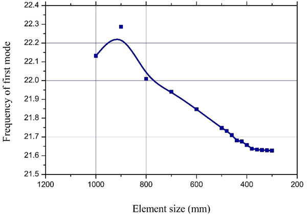
The series of differential equation bounded by certain boundary conditions usually solve the complex structural engineering problem. These differential equations are generally complex and difficult to solve using classical analytical methods over a required time domain. The finite element method is an approximate numerical technique to solve such equations. The convergence study is carried out on the whole modelled structure to find out the optimum mesh and can be performed on any of the solution variables. In the present study, the first mode of fundamental natural frequency is chosen. A plot between the frequency and mesh size is drawn and shown in Fig. (5). It is observed that the results are coming close when the mesh size is 300 mm, and the converged value of frequency is 21.62 Hz. So, the mesh size of 300 mm has been chosen for the analysis of the structure.
 |
(4) |
Further, a linearly elastic and dynamic analysis of the structural model is carried out which would be helpful to draw important information about the behaviour, interaction and performance of the structure. To obtain the solution of the model, discretization of the model into finite elements was done to solve them individually. Further, they all are merged by applying boundary conditions. The obtained results are interpreted to get other valuable information about the performance and response of the structure.
4.3. Static Analysis
In order to the behaviour of the Khusro Tomb due to its geometry, the linear static analysis was performed in ANSYS Workbench using vertical loads corresponding to self weight and live load. The analysis has been performed under constant vertical load i.e. self weight due to standard earth gravity as per IS: 875(Part 1)-1987. The live load of 0.75 kN/m2 (crew load) is applied at first floor level, second floor level and dome as per Indian standard IS: 875 (part 2)-1987. The linear elastic material behaviour is considered for the analysis. Static analysis is performed by providing fixed support at the base and resultant stresses are obtained in terms of equivalent von Mises stress.
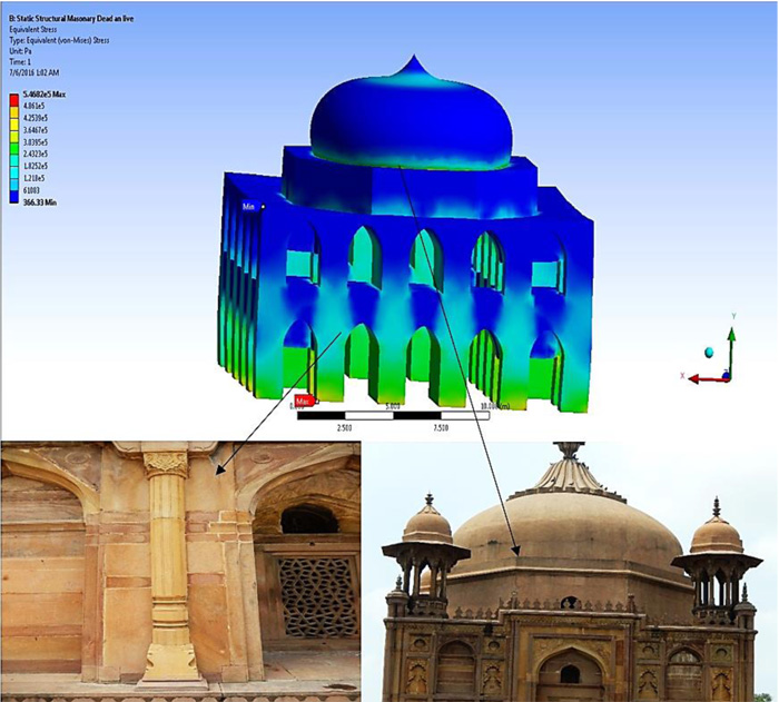
The maximum value of compressive stress of 0.547 MPa is generated at the base and bottom of dome of the structure. The maximum value of displacement 0.14 mm is obtained at the top of dome in vertical downward direction. The small value compressive stress of 0.12 MPa is obtained at the interior of the columns and second floor level of the structure. It shows that the symmetrical geometrical plan of structure distributes the load uniformly in the structure and (Fig. 6) demonstrates the variation of stress on the monument in the form of contour. The distribution of stress is uniform through out the Tomb due to symmetry in the plan. The maximum and minimum stress is in the order of ~10-1 N/mm2 and ~10-2 N/mm2.
4.4. Modal Analysis
To understand the dynamic response of the structure, modal analysis is performed. Mode shape of the structure is obtained by solving dynamic equilibrium equation
 |
(5) |
For free vibration analysis force vector f(t) = 0 and equation (5) can be simplified as
 |
(6) |
where [K] (stiffness matrix)= ∫[B]t[D][B]dυ;{xi} is mode shape vector, ωi is the frequency of ith mode, and [K] (mass matrix) ∫[N][N]tρdυ
The first and second modes are translation in transverse and longitudinal directions with fundamental frequency of 21.678 Hz and 21.679 Hz respectively, shown in Figs. (7a and b). First two modes are almost the same due to its symmetry about both x-axis and y-axis with a maximum displacement of 1.0081mm and 1.0073mm respectively. The third mode is a torsional mode with a fundamental frequency of 25.377 Hz, shown in Fig. (7c). The rest of the higher mode shapes are the combination of translational and torsional mode (Figs. 7 d-f). The free vibration mode shapes shown in Fig. (7), helps to characterize the displacement pattern of the structure. Table 2 shows all the six modes frequency. The higher mode response is having high influences on the top level shear and least influence on the displacement of structure. Tables 3a-c shows the mass participation for the Khusro Tomb.
| Mode | Frequency [Hz] |
|---|---|
| 1 | 21.678 |
| 2 | 21.679 |
| 3 | 25.377 |
| 4 | 35.816 |
| 5 | 42.177 |
| 6 | 51.76 |
4.5. Site Specific Time History Analysis
Superposition method of ANSYS Workbench 14.0 is used to know the behavior of time history analysis. Gravity loading results is combined with the time history results with appropriate sign convention. In the absence of strong ground motion record for Allahabad city, synthetic ground motion is simulated using the stochastic method [20]. Motazedian and Atkinson [21] had modified the method and the target ground motion amplitude spectrum, which depends on magnitude, distance and duration properties, is given by
 |
(7) |
where target amplitude spectrum corresponding to distance (r) and frequency (f) is represented by Aj(r,f), radiation pattern constant (Rθϕ, average value of 0.55 for shear waves), free surface coefficient (F, generally taken as 2), partitioning coefficient of shear waves (V) into two components (generally taken as  ), density of rock at source (ρ), shear wave velocity at source (υs), seismic moment related to the ijth sub fault (M0ij = corner frequency related to ijth sub-fault at time t (f0ij(t)), number of ruptured sub-faults at time t (Nr(t)), average sub fault moment due to each fault (M0,aυg =
  ), N total number of sub-faults, geometrical spreading function (G), effective distance of sub fault from the site (reff), quality factor at frequency f (Q(f)) and high frequency diminution filter, kappa (κ). The source duration is based on corner frequency and path duration, can be calculated by
 |
(8) |
The cut-off frequency relating to ijth sub fault is given by Motazedian and Atkinson [21] by
 |
(9) |
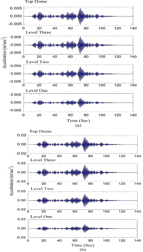
Where υs is in km/s, Δσ is in bars and M0,aυg is in dyne-cm. The parameters are used from the work of Singh et al [29] and Mitra [30]. The Stress drop for Indo-Gangetic Plains (IGP) is taken between 50-200 bars [31]. To achieve high amplitude of Peak Spectral Acceleration (PSA), stress drop values 150 bars the simulation has been estimated. The quality factor Q(f) for the IGP has been taken from the work of Mohanty et al. [32] as142f1.04. The geometric spreading function (G) worked out for the Indian region by Singh et al. [25]. The kappa factor κ for deep sediment filled layers, like Allahabad city (sediment depth is more than 1000 m), a higher value of kappa can be used in the range of 0.02-0.08. In the present research Kappa value of 0.06 is used. Time history generated due to the Allahabad fault is scaled down to 0.1g, 0.3g and 0.6g in order to show the response of KhusroTomb (Fig. 8). The effective duration of ground motion is approximately 80 sec. (Fig. 9a) shows acceleration response of all the level of Khusro Tomb for simulated Peak Ground Acceleration (PGA) input of 0.1g. The response of each level de-amplified with respect to input ground motion. It is observed that first floor response is ~33 times lower than the input ground motion. Further, the response of other levels increases gradually with respect to first level. The decrease in response may be due to stiffness of the Khuro tomb and frequency content of the input ground motion. Similar pattern is observed for scaled input of 0.3g and 0.6g. The displacement response of Khusro tomb is shown in Fig. (10). Table 4 shows the response on all the levels. The maximum displacement is an order of ~10-2mm for all the level. Further, it is also observed that reducing the material properties by 30%, the acceleration response is increased by~75% and displacement increased by ~60% compared to mean properties of the material. It is observed from (Table 4) that decrease in material properties significantly increases the response but the structure is in stable condition.

| Mode | Frequency | Period | Mass Participation Factor |
|---|---|---|---|
| 1 | 21.5704 | 0.46360E-1 | 0.113337 |
| 2 | 21.5714 | 0.46358E-1 | 0.692144 |
| 3 | 25.3615 | 0.39430E-1 | 0.251484E-8 |
| 4 | 35.5667 | 0.28116E-1 | 0.258454E-7 |
| 5 | 41.9698 | 0.23827E-1 | 0.282064E-7 |
| 6 | 50.3111 | 0.19876E-1 | 0.106939E-2 |
| Mode | Frequency | Period | Mass Participation Factor |
|---|---|---|---|
| 1 | 21.5704 | 0.46360E-1 | 0.151069E-9 |
| 2 | 21.5714 | 0.46358E-1 | 0.279714E-8 |
| 3 | 25.3615 | 0.39430E-1 | 0.539940E-9 |
| 4 | 35.5667 | 0.28116E-1 | 0.235378E-7 |
| 5 | 41.9698 | 0.23827E-1 | 0.318526E-8 |
| 6 | 50.3111 | 0.19876E-1 | 0.593882E-5 |
| Mode | Frequency | Period | Mass Participation Factor |
|---|---|---|---|
| 1 | 21.5704 | 0.46360E-1 | 0.692103 |
| 2 | 21.5714 | 0.46358E-1 | 0.113318 |
| 3 | 25.3615 | 0.39430E-1 | 0.320481E-7 |
| 4 | 35.5667 | 0.28116E-1 | 0.239057E-9 |
| 5 | 41.9698 | 0.23827E-1 | 0.834009E-7 |
| 6 | 50.3111 | 0.19876E-1 | 0.475217E-1 |

| E = 2000 (MPa) | Height from Ground(m) | Maximum Deflection(mm) | Maximum Acceleration (m/sec2) | ||||
|---|---|---|---|---|---|---|---|
| 0.1g | 0.3g | 0.6g | 0.1g | 0.3g | 0.6g | ||
| Top Dome (15.3) | 0.033176 | 0.099498 | 0.19906 | 0.0052626 | 0.015784 | 0.031576 | |
| Third Level (10.4) | 0.033611 | 0.10081 | 0.20166 | 0.0053513 | 0.01605 | 0.032108 | |
| Second Level (8.4) | 0.028826 | 0.086459 | 0.17296 | 0.0046063 | 0.013816 | 0.027638 | |
| First Level (5.0) | 0.018523 | 0.055557 | 0.11114 | 0.0029835 | 0.0089487 | 0.017901 | |
| E = 1400 (MPa) | Top Dome (15.3) | 0.053173 | 0.15952 | 0.319143 | 0.0092100 | 0.027630 | 0.055274 |
| Third Level (10.4) | 0.053823 | 0.16147 | 0.323004 | 0.0093293 | 0.027988 | 0.05599 | |
| Second Level (8.4) | 0.046118 | 0.13836 | 0.276787 | 0.0079977 | 0.023993 | 0.047996 | |
| First Level (5.0) | 0.029574 | 0.088721 | 0.177484 | 0.0051332 | 0.015400 | 0.030806 | |

CONCLUSION
The Khusro Tomb is the beautiful extraordinary example of Mughal Architecture with a trace of European style stone masonry structure, was the splendid structure of 17th century. Based on limited resources, reveals substantial information about 500 years the old monumental Structure. After carrying out the extensive survey about the dimensions and giving careful consideration in the 3-D modelling of the Khusro Tomb, a Static and dynamic analyses are performed on the 3D model. The model can be preserved for future references. In the gravity load analysis, the dead load i.e. self-weight of the structure including the weight of the finishes and live load i.e. crew load, is taken as 0.75 kN/m2 as per the codal provisions. The maximum stress is observed at the base and bottom of the dome of the structure. The small value compressive stress generated at the interior of the columns and second floor level of the structure. The maximum displacement of 0.14 mm is obtained at the top of dome in vertical downward direction. Dynamic analysis consists of modal and time history analysis to obtain the response of the structure, which provides information about the participated mass in a particular mode in respective directions. Site Specific time history results show that the structure is adequate to withstand the lateral force due to synthetically generated ground motion from the nearest Allahabad fault. Further decrease in material properties has significantly increased the acceleration and displacement response of the monument and the monument is still passable to withstand the lateral force.
CONSENT FOR PUBLICATION
Not applicable.
FUNDING
We are sincerely acknowledging Research and Consultancy cell, MNNIT Allahabad for funding this project.
CONFLICT OF INTEREST
The authors declare no conflict of interest, financial or otherwise.
ACKNOWLEDGEMENTS
Thanks to Archaeological department, Allahabad for allowing us to take measurements, etc. I am also thankful to the reviewers for their suggestion in improving the quality of the article.


