All published articles of this journal are available on ScienceDirect.
Mechanical Properties Evaluation of Functionally Layered Cement Composites
Abstract
Background:
Concrete mixtures are normally poured in single layers without intentional changes in the mixture properties within the thickness of the layers.
Objective:
In this research paper, alternative approach is introduced with Functionally Layered Concrete (FLC) composites, which have their known functions to achieve the maximum performance index.
Methods:
The performance index can be defined as the ratio of characteristics to the consumption of resources, fibres and additives. The steel fibre, polypropylene fibre, and silica fume are used in cement composites to make multilayer samples on which mechanical properties evaluations are conducted and compared to that of Mono-Layered Concrete (MLC) samples.
Results:
It is observed from the results that FLC samples have superior mechanical characteristics compared to MLC samples in terms of compressive strength, flexural strength and elastic modulus.
Conclusion:
Given that the use of fibres/additives in FLC composites is diminished, acquiring better mechanical performance with minimised consumption of resources would be possible via functionally layered composite method.
1. INTRODUCTION
In recent years, traffic load on runways for aircraft, traffic loading on the highways etc. has been increased intensively which requires strong pavements and there is a need to develop functional pavements desirably with no additional cost. The idea of FLC can be a great help to put up with these new demands. Strength of the ordinary concrete is one of the major components that contributes to its property. To further enhance its properties, additives are introduced [1]. Using different fibres and additives in concrete is the most efficient way to enhance the properties. This paper is aiming to propose a simple realistic model for multi layered Ordinary Portland Cement (OPC) pavements. The most significant advantage of FLC composites is to enhance the performance of the normal ordinary concrete with minimal contribution of additives, which can be highly cost efficient. This value-added type of concrete can have the maximum performance/cost factor. Tests for strength, such as compressive and flexural tests are carried out to find out the best design that gives the optimum results.
1.1. Steel Fibre and their Properties in Concrete
Steel fibre reinforced concrete is made from cement concrete mix which incorporated steel fibres as a reinforcing. Steel fibres will also be uniformity distributed like the cementitious material. Hooked end steel fibres, as shown in (Fig. 1), change brittle material into ductile one. Steel fibres are used to eliminate the biggest drawback of concrete, brittleness that can be improved by adding fibres of high tensile strength. The flexural strength is improved by 25% to 100% which depends on the volume of fibres added and design mix. Steel fibre reinforced concrete can be particularly used when the structure requires high strength resistance to impact loads, shrinkage control, erosion and abrasion resistance, high thermal and temperature resistance. The SRFC ranges between 1 to 2.5% in the plain concrete, which is the absolute volume [2]. It is required to maintain the desired volume in the concrete because it will affect the slump value as described in ASTM C143 (Standard 2015).

The hooked fibres shown in the Fig. (1) have different tensile strengths as explained in Table 1.
Different studies and tests were performed using steel fibres to enhance the ductility of concrete. A number of slab samples were prepared with varying percentage of steel fibres and tested and concluded that steel fibre increases flexural as well as compressive strength [3]. The ductile behaviour of concrete improved with the addition of steel fibres. The crack width in Steel Fibre Reinforced Concrete (SFRC) slab also decreased as compared to plain concrete. Generally, various strengths are improved with the addition of steel fibre in concrete and maximum strength depends upon the volume of steel fibre. However, the optimum volume of fibre that gives maximum strength, depends upon the type of strength to be determined.
1.2. Polypropylene (PP) Fibre and their Properties in Concrete
PP fibre-reinforced concrete is one of the advanced construction materials, which has been widely used these days. They are generally chemical fibres that are obtained from plastics produced from propylene gas. They are manufactured in factories using melt spinning. The propylene gas attained from the by-products of petroleum is being used in the production. They are mass produced around 4 million tonnes each year in the entire world. Under high temperature and pressure, these gases polymerise to form long polymer chain. To achieve the strength characteristics and mechanical properties, multistage process are done. The processed fibres show low density, high stiffness and resistance to chemical attack. In the early days, they were used as admixtures in the concrete for blast resistance in buildings. Further, the material has been improvised to achieve the desired quality and is now been widely used in the production of fibre reinforced concrete.
They are defined to show exceptional worth when comparing the other concrete. These types of concrete have high mechanical strength, high rigidity and durability. Normal concrete has limited ductility, less impact to abrasion and cracking and various other defects. So, various studies are being conducted to find a best alternative material that can show an increase in the strength and decrease in permeability. These benefits can be achieved incorporating PP fibres in the mix. Addition of fibres will improve the cracking behaviour, ductility enactment, toughness, impact resistance, flexural resistance. Using PP fibres in concrete will also encourage in overall reduction of materials and cost.
Various case studies and researches have been done on the PP fibre reinforced concrete to examine the strength characteristics and mechanical properties of concrete. Some of the conclusions that have been noted are as follows:
Workability: The air voids in the concrete increases with the addition of PP fibres, which further increases the air content in the concrete. This will toil the compaction and reduces the workability of concrete [4]. This will further lead to finishing problems in the structure. While no workability or segregation issues were showed when using monofilament fibres with fly ash in the concrete [5]. There were reports showing that the workability was only affected when the PP fibre content was higher [6].
Compressive strength: Failure to compression happens due to crushing and shear failure. Higher binding ratio between cement paste and fibre leads to higher compression strength. It is found that there is an increase of compressive, tensile and flexural strength when 1.5% of PP fibre is added in the concrete (Patel, Desai et al. 2012). Usage of fibrillated PP fibre having low density in high strength concrete with an addition of super plasticizer showed that the compressive strength of concrete was increased with the addition of fibres [4].
Shear strength: The shear strength showed an increase of 5% for M15, M20 and M25 grades of concrete [4].
Flexural strength: Research suggested that the flexural strength of the concrete is improved with the use of PP fibres [7]. However on the other side design guide, TR 34 states that adding fibres in concrete did not affect the flexural strength of the concrete [8].
Failure: PP fibres are inherent to cracking in concrete. These fibres increase the cohesion in beams. Addition of these fibres controls cracks due to its shrinkage properties [9]. Under three point loading test, it showed that the addition of fibres enhanced the failure limits of the concrete such as toughness, effective crack length, maximum deflection, critical cracking displacement and so on [10]. Other study conducted showed that PP fibres show extraordinary ductile properties and distribution abilities to put away the plastic cracks [11]. This fibres can be used to govern the properties of fresh and hardened concrete so that the fibres help in decreasing the plastic shrinkage [12].
1.3. Silica Fume and its Properties in Concrete
Silica fume is a by-product during the manufacture of silicon or other silicon alloys from the submerged-arc electric furnaces. This is used as a standby material in concrete to increase the durability, bonding strength, abrasion strength thereby decreasing the cement usage. However, sometimes its application in the concrete can be challenging due to its low bulk density making it difficult for storage and transportation. Various studies are done on the application of silica fumes with concrete to test various strength characteristics and other properties. Silica fume runs on mainly three mechanisms including 1) pore-size reinforcement & matrix densification; 2) reaction with free lime (mainly from the hydration of cement); 3) Interfacial refinement of cement-paste aggregates
New researches are going on to solve these issues possessed by silica fume and condensed silica fume is gaining popularity due to its high bulk density of around 400–720 kg/m2. The low bulk density enables the condensed silica fumes to be transported easily. The condensed silica fumes are prepared by blowing compressed air from underneath which will trickle the fumes in the silo which will prompt to the agglomeration of all particles [13]. These agglomerates are usually larger in concrete sometimes and obstructs their strength improvement from pore-size reinforcement & matrix densification mechanisms. Studies have shown the presence of CSH (calcium-silicate-hydrate) gel stirring up on the surface of the agglomerates which further improves the permeability, durability, and other mechanical and physical properties of silica fume concrete [14]. Studies also show that the agglomerates does not break down properly which will lead to the expansion and cracking of agglomerates [14, 15]. To solve this situation, agglomeration was done using ultrasound waves which will scatter the silica fumes in a better way which will make the particles more smaller in size [16, 17]. Another methodology is by the use of slurry silica fume which will also increase the density thereby solving the problems of transportation and agglomeration [18] but this has several disadvantages in storage, precipitation and so on because it is affected by the temperature changes . This has been further improved by granulation where the small particles of silica fumes are converted to larger particles without changing the physical properties [16]. Various additives can be used along with silica fumes to improve the properties of mixes. Mostly solid super plasticisers are used to improve the properties of silica fumes. The ideal ratio of the super plasticizer in the silica fume is said to be 6%-12% [19].
Compressive strength: Silica fumes are used as a replacement material in concrete to achieve a range of benefits such as improved mechanical properties and other physical characteristics. Compressive strength is one of the major parameters to look for in any type of concrete. In the case study done by artificial intelligence Artificial Neural Network (ANN) and Multi-Objective Grey Wolves Optimization (MOGWO) has been used to find out the compressive strength of silica fume concrete [20]. The compressive strength of silica fume concrete improved linearly with the addition of silica fume. The compressive strength is considerably affected by the aggregate size too. Around 5% difference in the strength can be seen if the silica fumes are much granular.
Flexural strength: Use of silica fume in concrete affects the properties of the concrete, it is investigated that the usage of silica fume by replacing cement content from 5 to 15% increases the flexural strength of the concrete [21].
1.4. Functionally Layered Concrete (FLC)
Nowadays, new construction methods and design mixes are being discovered. FLC makes construction activities more reliable and economical rather than using single layered conventional construction practices. The main purpose of using the FLC is to overcome the problems of the concrete pavements that we are facing by using MLC.
There are different materials that are used in multilayered concrete depending upon the requirement and geotechnical conditions of the site location
2. MATERIALS AND METHODS
2.1. Materials
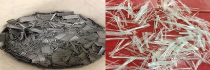
General Purpose (GP) Portland cement conforming the specification required as per AS 3972-2010 for General Purpose and Blended Cement was employed in this study. Coarse aggregate with the maximum diameter of 10 mm plus natural sand as fine aggregate with the specification described [22] were utilised to prepare the concrete mixtures. Steel fibre is the most common material used to increase the tensile strength of the concrete. Now steel is used in the shape of the fibre in concrete to make concrete better in tensile property; Hook-end Steel fibres, supplied by Dramix 65/60BG, with 60 mm of length, 0.45 mm of radius, aspect ratio of 65, and tensile strength of 1160 MPa. PP is used as a secondary reinforcement material in the concrete. PP fibres with 19 mm length, specific gravity 0.91, aspect ratio 475, and tensile strength 570-660 MPa from FORTA CAST-MASTER were utilised for reinforcement. In addition, silica fume, a pozzolanic mixture that is used to enhance the mechanical properties of concrete, is added to certain mixtures. Fig. (2) illustrates the steel and polymer fibres that are used in this work.
2.2. Experiments
To begin with, all the materials are brought in the room temperature (27 ± 3°C). Fine and coarse aggregates used in the examinations are dried in the oven. Then for dry mixing process, the OPC is mixed with aggregates thoroughly for 2 minutes to provide uniformity within the dry materials. The sufficient amount of fibres and silica fume according to the mixture proportions stated in Table 2 are measured and added to the dry mixture followed by 2 more minutes blending. Finally, water is added to the solids and the concrete was mixed for 2 more minutes to obtain reasonable consistency. The FLC samples are cast in a way the moulds are filled in two layers of different mixture with 10 minutes time gap between the layers. The moulds are also vibrated in two parts for 30 s/layer and specimens are left in the room temperature for initial setting. The hardened concrete was removed from moulds after 24 hours and kept in water till the testing time. The content of initial materials and added ingredients are selected based on the mixture proportions illustrated in Table 2.
| Sample Designation | Type of Sample | Water/OPC | OPC/Agg(a) (wt%) |
Steel Fibre (wt%) | PP Fibre (wt%) | Silica Fume (wt%) |
|---|---|---|---|---|---|---|
| O1 | MLC | 0.5 | 17 | - | - | - |
| O2 | MLC | 0.5 | 22 | - | - | - |
| O3 | MLC | 0.5 | 17 | 2 | - | - |
| O4 | MLC | 0.5 | 17 | - | 1 | - |
| O5 | MLC | 0.5 | 17 | - | - | 5 |
| FLCA | FLC | 0.5 | 17 and 22(b) | - | - | - |
| FLCB | FLC | 0.5 | 17 | 0 and 2(c) | - | - |
| FLCC | FLC | 0.5 | 17 | - | 0 and 1(d) | - |
| FLCD | FLC | 0.5 | 17 | - | - | 0 and 5(e) |
As shown in Table 2, five different mixtures were prepared in which the water to cement ratio is kept 0.5 constant. O1 is a benchmark that the other specimens are compared with. The OPC to aggregate (fine + coarse) ratio of mix O1 is 17 wt%, while it is increased to 22 wt% in samples O2. Mixtures O3 and O4 contain 2 wt% steel fibres and 1 wt% PP fibres respectively, as well mixture O5 has 5 wt% replacement of silica fume. Total 54 concrete samples are prepared from the mixtures explained in Table 2 from which 27 specimens are for compressive strength and other 27 ones for flexural strength evaluations. In total nine series of mixtures, which five of them are in MLC from (O1, O2, O3, O4, and O5) and four of them are FLC composites, were cast into the moulds. Mixture O1 is kept constant in all of the FLC samples for convenience in comparison and by that four FLC(x=A, B, C, D) mixtures are the combination O1 with O2, O3, O4, and O5 respectively. In other words, samples FCLA comprise two layers of O1 and O2 mixtures; samples FCLB comprise two layers of O1 and O3 mixtures; samples FCLC comprise two layers of O1 and O4 mixtures; samples FCLD comprise two layers of O1 and O5 mixtures. Therefore, the use of additives in FLC composite is almost half of the MLC sample.
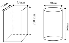
Three prisms and three cylinders, as shown in Fig. (3), per experiment are prepared to perform flexural and compressive strength respectively according to the ASTM C78 and ASTM C39 standards after 7 days of water curing.
Tecnotest 300 kN and MTS 50 KN machines are employed in order to perform compressive strength and flexural strength examinations respectively. The load application rate was kept on 0.25 kN/min constant for all of the tests. Fig. (4) illustrates the schematic representation of how the load is applied on the FLC samples.
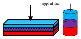
As illustrated in Fig. (4), each FLC sample contains three parts. The blue part is the benchmark mixture (O1), which is constant for all of them. However, the red part of the FLC samples can be any of O2, O3, O4, and O5 mixtures. In FLC composites, the second layer is cast before the setting time of the first layer. Hence, two mixtures combine together and form a functionally graded area as explained in ref [23]. The zone that forms in the middle of each FLC sample is illustrated by purple colour in Fig. (4).
3. RESULTS AND DISCUSSION
For early age compressive strength and flexural strength examinations, three samples per experiments are tested after 7 days of water curing and the average values are calculated. Values of compressive strength, flexural strength, elastic modulus, and toughness are measured and reported in this paper. Table 3 reports the mechanical characteristics of the MLC and FLC specimens.
| Sample Designation | Compressive Strength (MPa) | Flexural Strength (MPa) | Elastic Modulus (GPa) | Toughness (J) | ||||
| Average Value | STDV* | Average Value | STDV* | Average Value | STDV* | Average Value | STDV* | |
| O1 | 19 | 0.3 | 4.2 | 0.12 | 2.3 | 0.13 | 1.0 | 0.05 |
| O2 | 22 | 0.8 | 4.5 | 0.10 | 2.3 | 0.10 | 1.1 | 0.03 |
| O3 | 15 | 1.0 | 6.1 | 0.05 | 1.5 | 0.06 | 3.4 | 0.24 |
| O4 | 10 | 0.2 | 7.5 | 0.23 | 1.3 | 0.10 | 4.1 | 0.60 |
| O5 | 27 | 0.8 | 4.0 | 0.21 | 3.2 | 0.10 | 1.3 | 0.23 |
| FCLA | 20 | 0.8 | 4.0 | 0.20 | 2.4 | 0.28 | 1.2 | 0.13 |
| FCLB | 17 | 0.4 | 6.2 | 0.21 | 2.1 | 0.10 | 3.1 | 0.52 |
| FCLC | 17 | 0.8 | 7.4 | 0.08 | 1.9 | 0.26 | 3.7 | 0.18 |
| FCLD | 22 | 0.3 | 3.9 | 0.13 | 3.0 | 0.46 | 1.1 | 0.14 |
The average values of compressive strength, flexural strength, modulus of elasticity, and toughness (with the relevant standard deviation) of the normal MLC samples as well as FLC specimens are illustrated in Table 3. It is clear that changes in the mixture and addition of fibres affected the mechanical properties of the concrete samples. Table 3 reveals that 5% increase in the cement to aggregate (fine + coarse) ratio from sample O1 to sample O2 resulted in 16% enhancement in the early age compressive strength of concrete. Furthermore, addition of 2 wt% steel fibres in O3 and 1 wt% PP fibres in O4 mixtures caused 21% and 47% reduction in the 7-days compressive strength of the samples respectively. However, 5 wt% replacement of silica fume in the mixture O5 improved the early age compressive strength from 19 MPa to 27 MPa. The elastic modulus of the MLC sample follows a similar trend to that of compressive strength. Where the addition of steel and PP fibres decreases the elastic modulus and silica fume replacement leads to an increase in the modulus of elasticity. This is due the direct correlation between compressive strength and elastic modulus of concrete [24]. Nonetheless, flexural strength and toughness of MLC sample are positively influenced by the addition of steel and PP fibres. The effectiveness of steel fibres in the development of flexural strength of MLC sample is highlighted by 45% rise while this value for the PP fibres is 79%. Analogous trend is observed in the toughness as well.
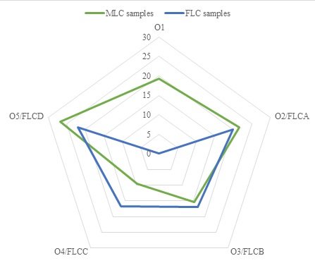
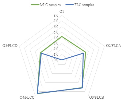
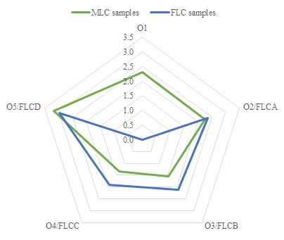
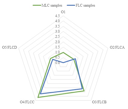
The idea of FLC composite can be advantageous when the desired changes in the characteristics of concrete can be achieved with a minimum usage of the additives. Therefore, drawing a comparison between the properties of MLC sample and corresponding FLC specimen is worthwhile. For this aim, Figs. (5-8) respectively compare the compressive strength, flexural strength, elastic modulus, and toughness in radar graphs.
The graphs of Figs. (5-8) contain two curves one of which (green configuration) is for the MLC and the other one (blue configuration) is for the FLC composite. The top corner of green pentagon in each graph represents the benchmark sample and the other corners are for the MLC sample with additives. Top corner of blue pentagons is bent toward zero showing that the number of FLC composite series is one less than MLC sample. From the top right corner of the radars samples O2, O3, O4, and O5 are respectively compared to samples FLCA, FLCB, FLCC, and FLCD. Accordingly, where the blue pentagons overlap/exceed the green ones, the FLC composites’ characteristics are equal/superior to that of MLC structure. In such a case, the use of FLC composite is highly recommended instead of MLC structure as the use of additive/fibre in FLC is half of the MLC sample, and it results in a value-added composite. Further, the mechanical characteristics of FLC composite and MLC sample are compared separately as follows.
Compressive strength Fig. (5): In O3/FLCB and O4/FLCC corners the blue line exceed the green line, which implies that the compressive strength of the FLCB and FLCC composites are higher than O3 and O4 samples. Referring back to Table 2, O3 and O4 samples are MLCs that contain steel and PP fibres. The compressive strength of MLCs dropped when the fibres were added (Table 3). However, switching to the FLC composite compensates the loss of compressive strength particularly in the case of PP fibre-reinforced specimens (O4 MLC to FLCC) by more than 60%. In O2/FLCA and O5/FLCD corners, where we have an increase in OPC/ aggregate ratio and 5 wt% replaced silica fume respectively, the compressive strength of the FLC composites is inferior but yet close to that of MLC samples. However, following the gridlines in Fig. (5), a boost in the compressive strength of FLCA and FLCD samples with respect to the benchmark (O1) is observed. The increase in the compressive strength of the FLCA and FLCD samples with respect to the benchmark can correlate to the fracture mechanics theory in the compression of the cubic samples and the role of FLC structures as the crack arrester [25]. Where the crack forms from one of the layers but will be arrested in the area between the layers, so-called functionally graded area, hence the propagation of the crack delays.
Flexural strength Fig. (6): In O3/FLCB and O4/FLCC corners the FLC pentagon seems to overlap the MLC pentagon, which means the fibre-reinforced FLC samples have competitive flexural strength to the MLC structures. It implies that achieving similar flexural strength with lower content of fibres is possible through FLC composite. This phenomenon is owing to the sample setup and direction of load application in the bending tests of FLC specimens. According to Fig. (4), when the load is applied on FLC composite, the blue area will be in compression and the red layer (reinforced layer) is in tension. The formation of the crack in bending test starts from the bottom of the samples and the propagation of the cracks continues up to complete failure. Undoubtedly, reinforcing the underlying layer of the composite samples will result in a delay in the formation of the crack, hence improving the flexural strength.
Elastic modulus (Fig. 7): The elastic modulus of the FLC samples compared to MLC samples follows a similar trend to that of compressive strength. According to Eq. 1 suggested by American Concrete Institute (ACI) codes, the elastic modulus of concrete has a direct relationship with the compressive strength.
 |
(1) |
where, f'c and Ec are the compressive strength, and modulus of elasticity in N/mm2 respectively.
Thus, it is expected that the modulus of elasticity follows a similar trend.
Toughness (Fig. 8): An increase in the toughness of the concrete composites are evidenced as a result of changing the composition and adding fibres/silica fume. The reason for change in the toughness of concrete is correlated to the change in the elastic modulus and the plastic area of the stress-strain diagram. As presented in Eq. 2, an increase in the specific fracture energy, which is directly related to the absorbed energy before failure, leads to a rise in the fracture toughness. On the other side, increase in the elastic modulus can negatively impact on the toughness. Given that the elastic modulus of O3 and O4 specimens are higher than FLCB and FLCC composites, the toughness of FLCB and FLCC composite specimens are less than O3 and O4 samples.
 |
(2) |
where, γ the specific fracture energy represents characteristic of fracture toughness, ϑ is Poisson’s ratio, and K1C is critical value of the stress intensity factor.
CONCLUSION
An alternative concrete composite for pavement was introduced by changing the mixture components of the concrete in a functionally layered orientation throughout the section of the structure. Mechanical properties of mono-layered concrete samples are then compared to functionally layered concrete specimens. The conclusions are as follows.
- The compressive strength results showed the superiority of FLC composites to MLC samples when steel and PP fibres are used to reinforce FLC specimens.
- The elastic modulus of MLC and FLC concrete follows a similar trend to that of compressive strength.
- Flexural strength of the FLC specimens was competitive to that of MLC samples given the fact that the use of fibres/additives in the form of multi-layer is much less than single-layer samples.
- Achieving similar and even better mechanical characteristics in the FLC composite implies that for addition of additive and reinforcement to the concrete, the composition of the different layers can vary depending on the application of the concrete.
CONSENT FOR PUBLICATION
Not applicable.
AVAILABILITY OF DATA AND MATERIALS
The data supporting the findings of this article are available within this paper.
FUNDING
None.
CONFLICT OF INTEREST
The authors declare no conflict of interest, financial or otherwise.
ACKNOWLEDGEMENTS
Declared none.


