All published articles of this journal are available on ScienceDirect.

Direct-Visual-Operation Support System for Unmanned Construction
Authors Info & Affiliations
Abstract
Introduction:
Unmanned construction through direct visual operation is performed to ensure the safety of workers at construction sites. In direct visual operation, although the equipment is simple and easy to install, the work efficiency and accuracy are reduced because of the lack of view and perspective obtained from boarding a construction machine. For solving this problem, images sent from multiple cameras, Unmanned Aerial Systems (UASs) attached to the construction equipment and the images obtained from boarding a construction machine, as well as blind spots are confirmed by displaying them on the monitor at hand. However, the working efficiency is lowered by the restrictions on the utilization range of the camera monitor, switching operation of the camera, and gaze movement between the construction machine and the monitor.
Methods:
For solving the problem of low work efficiency and accuracy of the conventional system, this paper proposes a support system for a direct visual operation that does not require monitor installation and gaze movement and enables intuitive camera switching operation by using a transmissive Head Mounted Display (HMD) and a stereo camera robot.
Results and Conclusion:
The results of the experiment conducted using a remote-controlled backhoe show that unskilled operators can perform the same quality of work as skilled operators, and work efficiency and accuracy was improved by 44.2% and 37.8%, respectively compared to the conventional system. This confirms the usefulness of the proposed system, especially for unskilled operators.
1. INTRODUCTION
Unmanned constructions to ensure the safety of workers at construction sites, including remote constructions by direct visual operation systems, are performed according to site conditions [1-4]. Recently, systems supporting operators who have no experience in remote construction are being researched to address problems such as a shortage of skilled remote-construction operators [5].
The direct visual system, in which an operator remotely controls a construction machine, is applied when the operating distance is within 50 m, and direct visual operation is possible [6]. It is effective when work is at dangerous and off-limit locations such as slopes or disaster recovery sites, or locations where the operator view is obstructed from the cockpit of the construction machine. Although the equipment is simple and easy to install, the reduction in the operational efficiency because of blind spots and differences in the view compared to the boarding environment is concerning [5, 7].
Therefore, a detachable unmanned vehicle camera system (OpeCam XIII – Operator Support Camera System XIII), which includes a video system, has been developed, where blind spots can be eliminated by the camera image [8, 9]. However, this required the installation of a camera monitor limiting the range of use, movement of the line-of-sight between the monitor and construction equipment, and switching operation of the camera, thereby reducing the work efficiency. In addition, the lack of a sense of depth in the 2D video reduced work accuracy [7].
Based on the parallax effect, by capturing two images with each eye, a sense of depth can be obtained. As the Head-Mounted Display (HMD) provides a sense of depth, a video system with a non-see-through HMD was developed [5, 10]. The work efficiency of remote construction was drastically improved by providing 3D images using an HMD, demonstrating that the image environment and sense-of-presence near the boarding time are critical [10]. Moreover, the equipment was simplified using an HMD, and the time and cost of construction work were reduced. However, unlike a direct visual system, it is impossible to work by watching the surrounding of the construction machine because this system is operated by viewing only the images from a boarding camera.
Unmanned Aerial Systems (UASs) and Unmanned Aerial Vehicles (UAVs) have been developed to enable workers to check blind spots and surrounding conditions of construction machinery [11, 12]. They can be moved and installed in inaccessible areas of the worksite faster than humans, reducing the possibility of human error at the construction site. However, they cannot be used for a long time due to their limited battery capacity, and require a separate operator to operate the UASs, in addition to the construction machine operator. In addition, they are less practicable when used in fieldwork because they are weak against the wind.
Given the above, this study proposes a system capable of presenting stereoscopic images from a stereo camera installed in the cockpit of the construction machine and performing a direct visual operation using a see-through HMD. To dispense with the visual line movement between the monitor and construction machine, we enable the confirmation of the video and construction machine in the same visual field. In addition, by synchronizing the stereo camera with the movement of the operator's head, the camera switching operation is not required, and intuitive camera operation is realized which further improves work efficiency. In addition, we aim to improve work accuracy by presenting 3D images.
2. MATERIALS AND METHODS
2.1. Proposed System
In the proposed system, a camera robot that includes three servomotors and a stereo camera is used along with a see-through HMD as the display monitor.
There are two types of see-through HMDs: video see-through and optical see-through. The video see-through blocks the user's field-of-view completely and shows the image photographed by the camera instead. In the optical see-through, the image of the micropanel is sent to the eye by reflecting it through a small optical lens and superimposed on the field-of-view in real space. In the proposed system, the optical see-through HMD is used as a support system for the direct visual operation. Thereby, the direct visual operation is performed with small eye movements because the image is observed simultaneously in the construction machine.
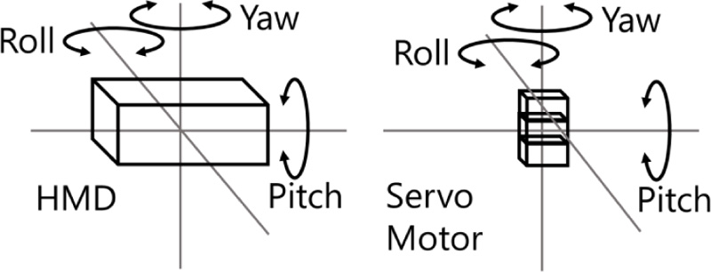
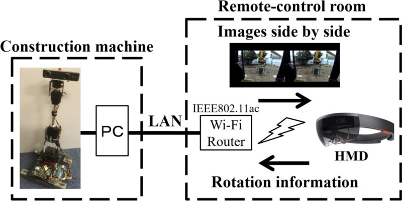
By presenting the 3D images acquired by the camera robot to the operator, a stereoscopic effect is generated. The rotation angles of the roll, pitch, and yaw axes of the HMD are acquired per head movement of the wearer by installing gyroscope and acceleration sensors in the HMD. The acquired rotation angle is transmitted to the camera robot. As shown in Fig. (1), a stereo camera is attached to the robot with three servomotors corresponding to the roll, pitch, and yaw, of the HMD. Each servo motor is controlled based on the rotation angle of the pilot's head received from the HMD and moves the camera according to the movement of the pilot's head. By synchronizing the direction of the see-through HMD with that of the installed camera, an image environment approaching the boarding environment is presented.
The rotation angle is transmitted from the sensor installed in the HMD to the camera robot installed in the cockpit. A video image of the stereo camera attached to the robot is transmitted from the camera robot to the see-through HMD. For communicating the rotation angle, a WebSocket that can communicate low-capacity messages at high speed, with low delay, is used [13]. For video communication, WebRTC, which is P2P video communication with low delay, is used [13].
The camera robot is attached to the cockpit of the construction machine, and the remote operator controls the see-through HMD. The operator performs the required work by confirming the camera image while directly performing the visual operation. As a see-through HMD is utilized, large-viewpoint transfer becomes unnecessary. In addition, as the camera robot synchronizes the head of the operator and camera direction, camera switching operation becomes unnecessary.
3. REMOTE-OPERATION EXPERIMENT
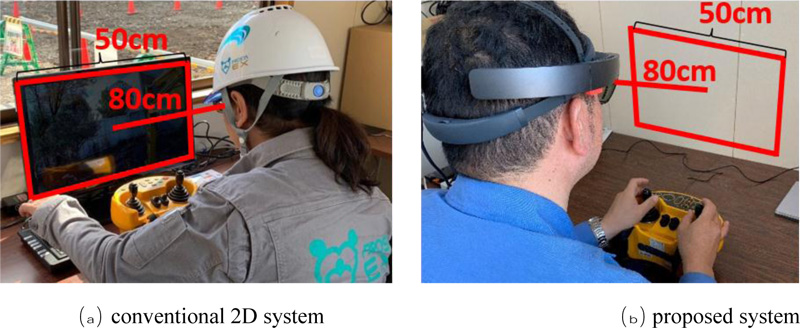
To confirm the usefulness of the proposed system, we compared the work efficiency and accuracy of the proposed system with that of an unmanned construction system with a 2D monitor, which is the conventional technique for direct visual observation. When a construction machine is observed over a see-through HMD, the same visual field as that in direct visual observation, when the image is not presented to the HMD, can be obtained. Moreover, a visual field equivalent to that of direct visual observation can be obtained by presenting the image such that it does not superimpose the construction machine. In this experiment, the image presented in the HMD alone was used to conduct the experiment assuming blind spots and accurate work, which are difficult to observe by direct visual observation. Thereby, it is possible to measure the effect on the work, using the presented image alone.
3.1. Construction of the Proposed System
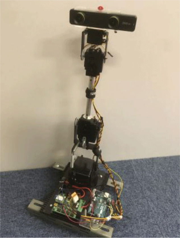
A remote-control camera robot was constructed using a six-axis manipulator (Lynxmotion AL5D), stereo camera (Zed mini), and microcontroller board (Arduino UNO) available in the market, as depicted in Fig. (2). As the rotation values of the three axes, roll, pitch, and yaw, can be acquired from the see-through HMD, three among the six servomotor axes can be controlled and correlated. A constant value was always set for the remaining three axes, and the robot was fixed to be vertical. The servomotor was controlled using the Arduino UNO board based on the rotation information of the pilot's head received from the optical see-through HMD; Microsoft HoloLens (specifications are listed in Table 1 containing a gyro sensor was used to acquire the rotation angle of the HMD. A remote-control-type backhoe SH 135 X -3 B (Nishio Rent All Co., Ltd.) was used for the experiment.
| _ | Details |
|---|---|
| Wireless | Wi-Fi 802.11 AC wireless networking |
| Optics/Display | 2.3-megapixel widescreen see-through holographic lenses (waveguides) 2HD 16: 9 light engines (screen aspect ratio) Holographic Density: > 2.5 k radiant (light points per radian) Automatic pupillary distance calibration |
3.2. Experimental Environment
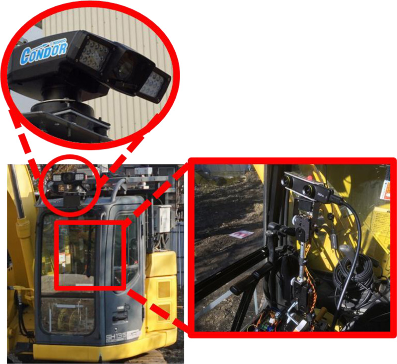
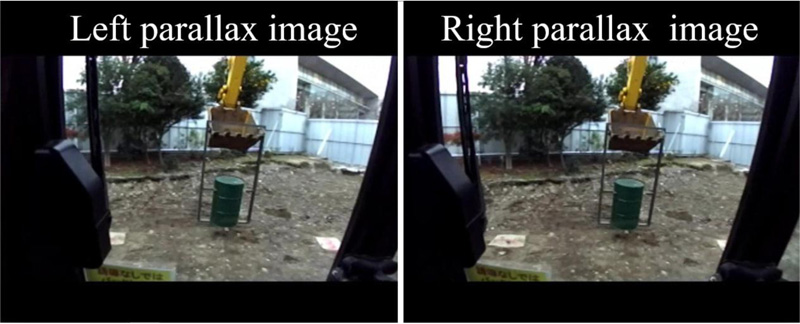
The stereo-camera robot was installed in the cockpit of the construction machine at eye-line height during boarding operation, and the image system camera was installed in the roof of the cockpit as in the conventional system. Fig. (3) shows the boarding seat after the installation of the camera robot. Fig. (4) depicts an image transferred from the installed stereo-camera. The resolution was reduced to
3.3. Experimental Procedure
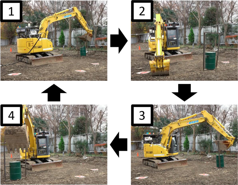
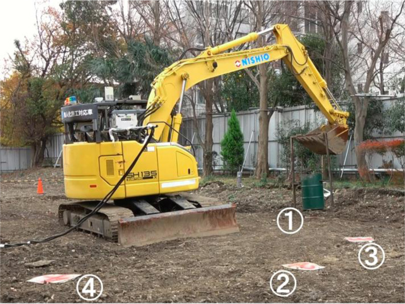
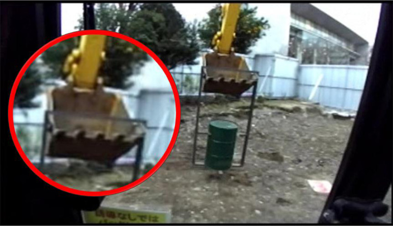
This experiment was performed based on a model task for the work efficiency evaluation of the remote-controlled hydraulic excavator [15]. Excavation by hydraulic excavators is generally affected by the difference in the number of piled buckets [15]. Therefore, for reproducibility, the work of scooping-up drum cans is considered similar to that of scooping-up earth, and sand, because it is difficult to obtain the piled quantity in the bucket each time. As shown in Fig. (7), a drum with handle was initially placed on 50-cm square mats at location one. The drum was required to be moved between four such mats, numbered 1-4, in the following order: 2, 3, 4, 1, at the end of which one cycle was completed and the process again repeated. The experimental duration per operator was set to 30 min with reference to the 3D work guideline [16, 17]. The handle was made larger than the width of the construction machine bucket by several centimeters, as high precision work was required. It was necessary to scoop the drum can by lowering the bucket to the ground each time it was transferred to a mat. The worksite is depicted in Fig. (8). The same work was performed once for each of the conventional 2D system and the proposed system. Before the experiment, the operators were made to practice on both the systems until there was no operator error.
3.4. Evaluation
The average work time required for one cycle is calculated as the work efficiency. The average work error, which is the distance of the drum from the center of the mat, is calculated as the work accuracy.
3.5. Participants
Two vehicle-type construction machine operators with boarding operation qualifications and no experience in unmanned construction participated in the experiment. Participant-1 was a skilled operator who operated daily, whereas participant-2 was unskilled and operated only during experiments for research.
3.6. Results and Discussion
Table 2 lists the average working time for each participant, and Table 3 presents the results of the average work error. The work accuracy and efficiency were impaired for skilled operators (participant-1), whereas both drastically improved for unskilled operators (participant-2).
| - | Participant 1 | Participant 2 | Average |
|---|---|---|---|
| (1) 2D System | 6:17 | 11:07 | 8:42 |
| (2) Proposed System | 9:23 | 6:12 | 7:48 |
| Difference (2) – (1) | 3:06 | -4:55 | -0:54 |
| - | Participant 1 | Participant 2 | Average |
|---|---|---|---|
| (1) 2D System | 4.69 | 12.30 | 8.50 |
| (2) Proposed System | 5.71 | 7.65 | 6.68 |
| Difference (2) – (1) | 1.02 | -4.65 | -1.82 |
For participant-1, the average work error with the proposed method was + 1.02 cm (a 21.8% reduction in the work accuracy), and the average work time was +3 min 6 s (49.6% reduction in the work efficiency), compared to the 2D system. The work efficiency of skilled operators may have decreased because of the 430 ms delay in the display in the communication system used in this experiment. In addition, the experiment included scenarios in which experienced operators performed operations through a sense of habit compared to the unskilled worker. Therefore, skilled operators were more likely to be affected by the delay because they cannot easily perceive the effect of environmental changes when high-precision work is required, resulting in unnecessary operations such as frequent stopping, and increased time to return to work because the bucket was moving too much. However, as the conventional 2D system did not sense the delay, work was performed at a stable operating speed. To suppress delay, transfer was carried out by reducing the resolution. Therefore, the resolution of the conventional 2D system was set at
For participant-2, the average work error was -4.65 cm (a 37.8% improvement in the work accuracy), and the average work time was -4 min 55 s (44.2% improvement in the work efficiency). The delay of approximately 430 ms may not have affected the operation considerably because the unskilled operator was operating more slowly than the skilled one. Therefore, the usefulness of the 3D image and the image environment close to the boarding time can be considered to be greater than the effect of the delay for the unskilled operator, enabling smooth work compared to the 2D system. As a result, work efficiency drastically improved, and the same quality of work as that by a skilled operator was realized. The improvement of both items for participant-2 confirmed that the system could be used without any special training.
Previous studies indicated that with a delay of 430 ms, the working time was reduced by approximately 30% compared to that with a delay of 230 ms [18]. Therefore, by suppressing the display delay time to 230 ms or less, the work time can be reduced by approximately 30%. In addition, in the experiment, because communication was performed using Wi-fi, a delay of 430 ms occurred even when the resolution was reduced. From the viewpoint of low delay and high resolution, the use of commercial video transmission equipment is conceivable. For example, Teradek Bolt is a latency-free wireless transmission system for cameras that can achieve uncompressed trans-missions. A significant improvement can be expected by using this.
For the proposed system, the average work error was -1.82 cm (work accuracy improved by 21.4%), and the time was -54 s (work efficiency improved by 10.4%); thus, both parameters exhibited improvement.
In recent years, problems such as shortage of operators for unmanned construction machines have contributed to the development of unmanned construction technology, where the operating environment resembles that at the usual driver's seat, the operation can be performed similar to that in a boarding environment [5]. In addition to monitoring the cameras used for remote control, 3D cameras and omnidirectional cameras are used to increase the visual information. By acquiring not only visual information, but also the sound field, and the vibration and inclination of heavy machinery through sensors and reproducing them in the remote-control seat, field information is provided to the operator, and the operating environment approaches that of the boarding environment. Moreover, 3D and omnidirectional cameras are used to enhance the visual information. Thus, the work efficiency is improved for unmanned construction. Further improvements can be expected by rendering the proposed system closer to the boarding environment.
CONCLUSION
This study proposed a support system for direct visual operation in unmanned construction using a see-through HMD. By applying this HMD, problems in conventional systems including the limitation of the application range by monitor installation, large eye-movement between the monitor and construction machine, switching operation of the camera, and the 2D image were improved, and improvements in work efficiency and work accuracy were achieved.
A robot equipped with a stereo camera was installed in the passenger seat to photograph the 3D image to be transferred to the HMD. By matching the direction of this stereo camera with the movement of the head of the operator who wore the HMD, an image approaching that of the boarding environment was recreated.
Using a conventional 2D system and the proposed system, an experiment was performed with an actual machine. Compared to the experimental results of the skilled operator using the 2D system, the average working time of an unskilled operator using the proposed system was -5 s, whereas it was + 290 s with the 2D system; the average work error was + 2.96 cm, whereas it was + 7.61 cm with the 2D system. In addition, the proposed system can address the issue of skilled-operator shortage because it enables unskilled operators to perform work of the same quality as that by skilled operators. The image environment near the boarding time in the proposed system functioned effectively for the unskilled operator, establishing the usefulness of the proposed system. Moreover, by using a see-through HMD instead of a camera monitor, it was possible to eliminate the limitations caused by monitor installation.
In contrast, for skilled operators, the delay and resolution affected the work, resulting in a slight decrease in work efficiency as well as accuracy. However, work-efficiency improvement of more than 30% is expected by improving the delay, based on the results of previous research. In this study, only one skilled and unskilled operator, each, were employed; in the future, it is necessary to perform the experiment using more operators. As the experiment was performed by excluding the effect of the direct visual operation, it is necessary to conduct the experiment simultaneously along with the direct visual operation in the future.
CONSENT FOR PUBLICATION
Not applicable.
AVAILABILITY OF DATA AND MATERIALS
Not applicable.
FUNDING
The study is supported by Tokyu Construction Co., Ltd. Grant code number is 18TC09.
CONFLICT OF INTEREST
The authors declare no conflict of interest, financial or otherwise.
ACKNOWLEDGEMENTS
This study is the result of joint research by the Tokyo City University and Tokyu Construction Laboratory Co., Ltd. We would like to express our sincere gratitude for the cooperation of Tokyu Construction Laboratory Co., Ltd., not only in the experiment, but also for ensuring the safety of the test site and arranging the equipment.

