All published articles of this journal are available on ScienceDirect.

Consolidation in Soft Soil – Case Study on Prefabricated Vertical Drains (PVDs)
Abstract
Background:
Constructing on soft ground is one of the challenges of geotechnical engineering. The unpredictable behaviour and characteristics of soft soil can cause much damage resulting in high maintenance costs in the post-construction phase.
Objective:
The purpose of this study is to analyse the consolidation process and ground improvement method using surcharge and a prefabricated vertical drain by measuring the accuracy of the prediction settlement value with the actual site settlement results.
Methods:
An effective ground improvement method is the application of a surcharge and prefabricated vertical drains (PVDs). Various methods can be used to predict the settlement effectively, one such method being PLAXIS 3D simulation. A case study on ground improvement works was selected for this research, where PVDs were constructed and implemented at the site. A few undisturbed samples were collected from the site to generate the parameters based on the lab test conducted in the simulation process. This parameter was carefully studied and representing the principal input for the 3D model, which is generated and represents the actual ground improvement method for the selected case study. The analysis was performed using a borehole and soft soil model to generate the diagram. The prediction settlement value was generated from the PLAXIS 3D analysis as the baseline comparing to the actual results. The factors that influence the settlement value, such as the length and spacing of the prefabricated vertical drain, construction method, and soil characteristics, are also discussed.
Results:
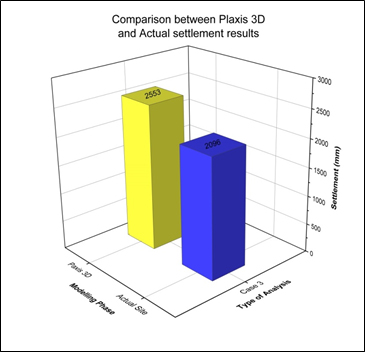
A predicted settlement of 2553 mm was generated by the simulation, while the actual settlement outcome at the site was 2096 mm, a difference of 457 mm, and a prediction accuracy of 82.1%.
Conclusion:
The study found that the combination of surcharge and prefabricated vertical drain in the ground improvement worked well. Also, discussed were the factors that influenced the accuracy of the prediction and the site results.
1. INTRODUCTION
Construction on soft ground is one of the challenging tasks in geotechnical engineering. The soft soil behaviour and characteristics, which are unpredictable, have caused significant damage and wasted significant sums of money in performing maintenance work following the post-construction phase. Indeed, construction engineers must deal with time limits and other restrictions in finishing the construction project by improving soil stability in accelerating the settlement process [1]. Venice is one of the notable cities constructed under soft soil and a pioneer in a case study for ground improvement engineering. Complex engineering in the construction of the City of Venice established a prime example of the technique for handling the consolidation process. From the data attributable to the city, Venice has been falling during the past 30 years by up to 260 mm/year to a depth of around 300 m. It was inevitable that the consolidation of the subsoil and consequent settlement of the ground surface would occur, given these reductions in pore water pressure [2].
The city's subsoil profile shows a layer of hard clay called Caranto, extremely fine-grained sediment that has undergone a process of over consolidation in a subaerial environment and withstands weight better than soft mud. The subsoil profile consists of irregular alternations of silt, very silty clay, clay loam and medium to fine sand with some uncompacted peat layers. The layers are shared with normal and over consolidated soils with a depth of 60 m. The deep foundation used to construct the city of Venice was by using timber that was under the sea in which two phenomenons kept the timber protected from rot [3]. The first phenomenon was that the timber remained under the sea, with no presence or exposure to air. The second phenomenon was that the timber absorbed the deposited sediments, allowing the timber to be highly durable. With these ground conditions, the buildings were built having a solid base.
The construction of the city of Venice city established an excellent engineering example for ground improvement work. Basically, for soft soil, excess water is the main problem in the soil, leading to failure and acts as a mechanism to reduce the volume of water in the soil; thus, increasing the shear strength, which is the focus in geotechnical engineering. These processes are defined as consolidation and settlement. Consolidation occurs where the process discharges water from the soil by applying a surcharge. This process is governed by the rate of dissipation of excess pore pressure, the coefficient of consolidation (Cv) of the soil, and the thickness of the consolidating layer [4]. The coefficient of consolidation in the vertical direction (Cv) for each idealised stratum at every subdivided location is determined based on the pressure of the proposed embankment.
On the other hand, for the coefficient of consolidation in the horizontal direction (Ch), the values can be correlations that could be referred to determining Ch, such as the time factor method [5] and the simplified relationship method [6]. Consolidation is the gradual reduction in the volume of a fully saturated soil of low permeability due to drainage of the pore water. The process continues until the excess pore water pressure set up by an increase in total stress has been completely dissipated [7]. Consolidation comprises three phases, namely: the initial compression, primary consolidation, and secondary compression phase. For a fully saturated clayey soil, the initial compression occurs immediately after a load is imposed, and the shape of the clay layer changes. This is because the low permeability of the soil causes it to be undrained, and when a load is applied, there is both vertical compression and lateral expansion of the soil. The primary consolidation phase develops when the stress induced by the external load is immediately borne by the water, which is assumed to be incompressible, and the excess pore water pressure gradually dissipates as water seeps out from the soil through drainage boundaries, and the pressure is transferred to the soil skeleton [8].
The secondary compression phase involves the long-term settlement that occurs because of the continuous movement that results from the reorientation of the soil particles. The creeping process gives rise to changes in the volume and increased settlement. This consolidation process can be accelerated by focusing on two options, first, by increasing the surcharge or secondly, by reducing the length of the drainage, subject to the site conditions and suitability of the subsoil. Suppose an analysis reveals that increasing the surcharge by constructing a high embankment may cause stability problems. In that case, the best solution is to shorten the time taken for the pore water to travel to the drainage boundaries. Time and cost are critical issues monitored in a project involving ground improvement works [9]. In order to achieve this, the use of Prefabricated Vertical Drains (PVDs) is highly recommended to accelerate the rate of radial drainage and consolidation, which will impact the duration and cost of the project.
Moreover, several projects that used PVDs as a major soft ground improvement technique to improve soft deposits had an excess settlement, briefly after the projects had been in service [10]. In most PVD designs, it is understood that the surrounding soft soils are homogeneous and that the subsoil profiles are similar, based on several borehole tests and samples. Little attention is given to the geometry of the PVDs, particularly during their installation at the project site.
This is due to the compilation of the settlement and consolidation computations in the multi-layered ground and the choice of the layout, including the spacing and depth of the PVDs, which remain very much trial and error [11]. The most important consideration when designing a PVD is that it must be capable of reducing the length of the drainage path and the spacing of the drains [4].
Many engineers prefer to carry out the ground treatment method rather than proposing a deep foundation at the soft soil area, given it is more economical. Based on previous research, the various techniques available for the consolidation process in soil are shallow compaction, preloading sand drains, vibrofloatation, admixtures stabilisation, deep mixing, stone columns, sand columns, jet grouting and deep compaction by using piles [12].
This research was conducted to identify the various factors involved in the performance of PVDs at Kuala Gula to study the ground improvement work in soft soil areas. Then, the improved ground method by using PVD is then combined with the simulation applications for the prediction process to validify its effectiveness to the ground work.
1.1. Prefabricated Vertical Drains (PVDs)
A Prefabricated Vertical Drain (PVD) is a type of vertical drain comprised of a geotextile jacket surrounding a plastic core designed to prevent clogging and increase the rate of consolidation by reducing the flow path of the pore water. With the installation of a PVD, the pore water can travel faster by flowing horizontally to the drain and vertically by pressure through the drain until discharged at the drainage layer [13]. For a given subsoil condition, the effect of the vertical drain depends on several factors: (i) the drain spacing and equivalent drain diameter; (ii) the well resistance (discharge capacity); (iii) the smear effect, and (iv) the drainage boundary condition [14]. The consolidation time is equal to the square of the distance the water must travel to exit the soil [15]. The effectiveness of a PVD depends on the soil conditions, the material and characteristics of the drain, and the quality of the work during the construction or installation process. However, a PVD cannot perform if the effective stress imposed is less than the pre-consolidation stress. In addition, a PVD is also required to have a specified tensile strength so it can achieve a specific permissible elongation without affecting the main dimensions of the drain [16]. PVDs are not possible to accelerate consolidation if press effective stress is not more than pre consolidation stress [17]. The benefits of installing PVDs include the following:
(a) Reduces the time required to complete the primary consolidation.
(b) The volume of the surcharge can be reduced to achieve consolidation.
(c) Increase the shear strength of the soft soil when stability is of concern.
(d) Fewer environmental problems concerning the disposal of damaged materials.
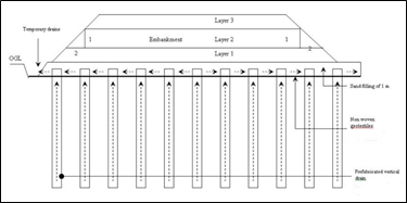
PVD drains are appropriate for certain types of soils that possess a moderately to highly compressible layer under static loading and a shallow compressible layer under natural drainage conditions due to low permeability and far from the natural drainage boundaries. Such soils include inorganic silts and clays with low-moderate sensitivity, organic silts and clays, and decomposed peat. Among the vertical drains available include PVDs and are very popular since they are the most economical, cause less disturbance to the soil, and can be installed quickly and effortlessly. Fig. (1) illustrates a cross-section of a typical PVD system and its preloading combination. It also shows the flow of the pore water, which is discharged during and after the application of the surcharge. A temporary drain is necessary for the design since it will divert all the water discharged from the PVD through the sand layer or drainage layer.
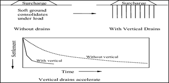
Prefabricated Vertical Drains (PVDs) can be installed vertically to a depth not exceeding 60 m, depending on the installation method. The installation of PVDs is suitable for projects with a longer construction period to ensure that the required degree of consolidation can be achieved. PVDs are also called wick drains, and this term is used since the water is not wicked out of the ground by the drains under a capillary tension, but instead, the water flows into the vertical drains from a compressible soil layer subjected to a temporary water pressure gradient induced by the placement of a permanent fill and temporary surcharge fill. The required permeability for PVDs, especially geotextile PVDs, should be 10-fold more than that of the surrounding soil [18]. It is also very important to stabilise the soft soil before commencing any major construction work to prevent settlement (Fig. 2). Effect on the settlement with and without PVD (adopted from PVD system for the construction of an embankment on compressive soft soil, 2004), as shown in Fig. (2), describes the effect of PVDs on ground treatment work. It shows that the rate of settlement was faster with than without the PVDs.
1.2. Performance of PVD
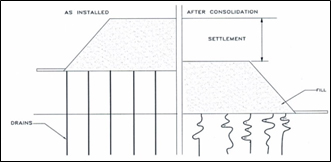
The vertical drains are subjected to both tensile and compressive forces as the soil shifts and settles. A vertical soil settlement can cause some drains to be pinched off due to the folding and buckling of the core, affecting the drains' ability to perform efficiently. Therefore, the performance of the drain must be considered under both conditions, as failure to do this will undoubtedly impact the project schedule (Fig. 3). Drain deformation during consolidation (adopted from PVD system from the construction of an embankment on compressive soft soil, 2004 (Fig. 3) shows the deformation that occurred to the PVDs following the consolidation process. The PVDs must be designed for flexibility and durability to perform to their maximum capacity in discharging the pore water without developing kinks during the consolidation process. It is clearly shown that when the clay permeability is low, it will be necessary to reduce the PVD spacing so as to shorten the consolidation period [19]. The closer the spacing between the PVDs, the shorter the time required for the consolidation process [20].
According to a case study on a design and build project in Salt Lake Valley, the field tests indicated that PVDs having a spacing of less than 1.75 m do not significantly change the settlement rate [21]. The drain spacing may be varied to optimise the design, and when the drains are installed closer to one another, the consolidation time will be reduced, although the installation costs will increase [22]. A case study was also carried out on the influence of spacing in consolidation. Here, a few spacings were tested at the Saga Airport to test the embankment where the result showed the average degree of consolidation of 90%, 95%, 99% and the spacing for 2.0 m, 1.5 m, 1.22 m, respectively, with the actual design of 1.5 m [23]. Based on the test embankment result, it is shown that the spacing of the PVD does influence the consolidation rate. This is because the compilation of the settlement and consolidation computations in the multi-layered ground, and the choice of the layout, including the spacing and depth of the PVDs, remains as trial and error [24].
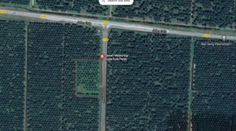
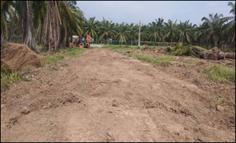
For this study, this project involved constructing a radar building with supporting facilities for the administration and staff quarters. Fig. (4) shows the project's location at Kuala Gula, in the Kerian district of Perak, Malaysia. A soil investigation was conducted to acquire the subsoil profile and characteristics to determine the soil's behaviour. Oil palm plantations surrounded the project area, and the subsoil consisted of soft clay, as shown in Fig. (5).
2. MATERIALS AND METHODS
2.1. Subsoil Profile
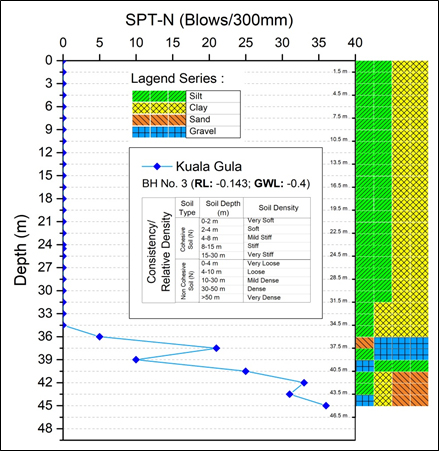
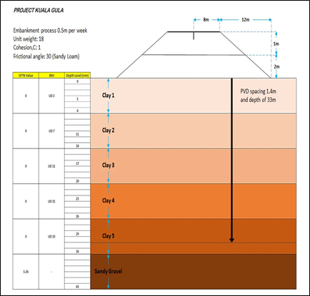
For this project, a surcharge with PVDs was selected for the ground improvement design. The ground improvement technique depends on the soil properties, site or ground conditions, design loads, size of the treatment area and the purpose of the construction [25]. A soil investigation as to study the behaviour of the soil. Fig. (6) shows the standard penetration test that was undertaken, where borehole number 3 was chosen for the data collection task. Table 1 describes the subsoil profile that was generated from borehole number 3. The soft soil layer had a depth of up to 36 m and consisted of one type of soil, namely, clay, for the undisturbed samples 1 to 5. For the ground improvement work, it was suggested that an embankment of up to 2 m be constructed with a surcharge of 1 m.
In order to increase the consolidation rate, PVDs were proposed with a spacing of 1.4 m, in a triangular pattern and terminating at a depth of 33 m to achieve the required degree of consolidation. The length of the PVD is important since it can influence the deformation pattern of the subsoil [26]. The discharge capacity of the drain depends on the drain condition, the rate of water flow and long discharge behaviour [27]. The fill material comprised of sandy loam, with a bulk density of 18 kN/m2. The area for the ground improvement work had a length of 90 m and a width of 42 m.
| No. | Description | Depth (m) | N (blows) |
|---|---|---|---|
| 1 | Silty CLAY | 0 -36.0 | 0 |
| 2 | Grey Silty GRAVEL | 36.0 -37.5 | 5 |
| 3 | Grey Silty GRAVEL | 37.5 – 39.0 | 21 |
| 4 | Clayey SILT | 39.0 – 40.5 | 10 |
| 5 | Silty SAND | 40.5 – 42.0 | 25 |
| 6 | Silty SAND and GRAVEL | 42.0 – 43.5 | 33 |
| 7 | Silty SAND and GRAVEL | 43.5 – 45.0 | 31 |
| 8 | Silty SAND and GRAVEL | 45.0 – 45.5 | 36 |
2.2. Ground Improvement Design
2.2.1. Settlement Analysis
The equation [[22] was used to analyse the total settlement given as Eq. (1):
where: mv is the coefficient of volume compressibility,
H is the thickness of the layer, and
σ is the stress.
First, from a one-dimensional consolidation test, the coefficient of volume compressibility, Mv was obtained with a coefficient of consolidation, Cv, at a specific applied pressure (Eqs. 2 and 3).
2.2.2. Log-Time Method
From the experimental curve plotted in Fig. (7). Square root fitting method, an initial curvature was present before the straight line due to the compression of the air in the voids of the soil. If a line were to be drawn, according to Fig. (8), from the origin, with the abscissa equal to 1.15-fold that of the theoretical curve, the two would intersect at U = 90.
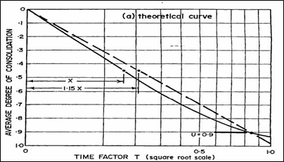
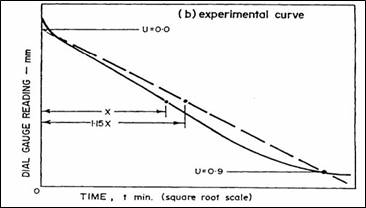
The time, t90 corresponding to U = 0.9 was read from the experimental curve, and the coefficient of consolidation was calculated from Eq. (4);
2.2.3. Surcharge and the Cross Section
A surcharge aims to create a higher pressure than the pressure during the service life to accelerate the consolidation settlement and thus reduce the long-term settlement. The thickness of the surcharge material and the duration of the surcharging was controlled by the total settlement analysis, the permeability of the subsoil, and the available construction period. Usually, the surcharge is used together with PVDs installed in a soft compressible layer with low permeability. In other words, the depth of the PVD determines its capability to discharge the pore water [28].
Fig. (9) shows the subsoil profile for borehole test number 3. The soil profile was up to a depth of 45 m, consisting of five different layers of clay having unique characteristics based on the nature of the soil, with a sandy gravel layer at the bottom of the clay after the soft soil layer. Each layer was projected in a different colour, according to the characteristics and soil parameters, including the SPT-N value. The original design for the ground improvement work, in this case, was to construct a 3-metre-high embankment with PVDs spaced 1.4 m apart in a triangular pattern up to a depth of 33 m.
2.2.4. Settlement Analysis
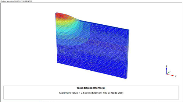
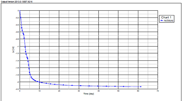
Finite element analysis was conducted using PLAXIS 3D in plane strain modelling. Numerous types of constitutive soil models have been developed based on stress-strain mechanics and other theories, such as plasticity and elasticity that include very complex mathematical equations. PLAXIS allows for the simulation of staged constructions concerning drained or undrained conditions for different loads and ground conditions. According to a study [29], geotechnical applications require advanced constitutive models to simulate the non-linear, time-dependent and isotropic behaviour of soils. Regarding Fig. (10), the predicted total settlement readings were 2553 mm in 6 months and 2664 mm in 90 months, with the post-settlement reading for five years as 111.3 mm, which is below the requirement of 250 mm. Fig. (11) displays the settlement versus time graph generated using PLAXIS 3D, where the settlement of 2553 mm was starting to become stagnant after five months during the rest period.
2.3. Site Construction
The preparation of the site for the ground improvement works needed to be undertaken in stages for the construction. First, the site had to be cleared of all types of plants and debris. Then, a non-woven geotextile had to be laid at the treatment area to strengthen the top layer of the soft soil, and concurrently, to function as a separator. After laying the non-woven geotextile, the filling process is then conducted with sand. This filling process was intended to prepare a working platform for the installation of the PVDs. This sand layer was part of the drainage blanket. The minimum thickness of this drainage layer was 0.5 m. This was next followed by installing the PVDs with a spacing of 1.4 m, according to the original design, and terminating at a depth of 33 m. After installing the PVDs, the filling work continued with the drainage layer up to 0.5 m. The following monitoring instrumentations were provided for the areas involved in the proposed embankment and retaining structures:
(a) Surface settlement marker: to monitor the vertical movement of the ground due to the embankment fill.
(b) Rod settlement gauge: to monitor the settlement of the subsoil and to establish a settlement profile for the planning and control of the construction.
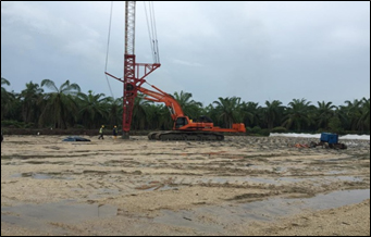
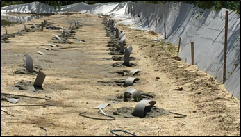
The instrumentation monitoring scheme was scheduled to be implemented during the embankment construction and would continue for a certain period, even after completing the construction. Usually, frequent monitoring is implemented during the construction stage upon completion of the embankment. The filling process was continued at a rate of 300 mm per week after installing the instrumentations. The filling was compacted at a dry density of 95% every 500 m2. Fig. (12) shows the installation of the PVDs according to the layout, and Fig. (13) shows the completed installation of the PVDs at a spacing of 1.4 m in a triangular pattern up to a depth of 33 m.
3. RESULTS AND DISCUSSION
3.1. Actual Site Results
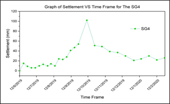
The ground improvement work using PVD and surcharge was monitored and verified using geotechnical instrumentation. For this case study, a settlement gauge (SG4) was used. The time required for consolidation to achieve the required settlement was successfully achieved using the PVD and surcharge as the ground treatment work. The monitoring process from the beginning or outset of building an embankment until the settlement reading decreases was undertaken in eight months. Ground settlement in Fig. (14) shows the settlement tends to fluctuate at the beginning of the embankment construction and rapidly increases once the embankment is completed for 3 metres, including the surcharge. The highest settlement occurs at the 4th month of the consolidation process with a reading of 100 mm. This phase is called primary consolidation, and once this process completes, the rate of settlement tends to slowly increase until depleted. The total settlement for this SG4 is 2096 mm in 6 months.
Based on the ground improvement design of the project, the combination of preloading and PVDs was utilised as a treatment method. In this case study, the design for PVDs was 1.4 m in a triangular pattern up to a depth of 33 m. This follows with constructing an embankment for a 3-metre height and a resting period of eight months. Before implementing this method on the site, the simulation process was conducted using PLAXIS 3D to obtain the prediction settlement value as the baseline and comparison purpose for this ground improvement work. The soil parameters were generated from the 1D consolidation test for the five undisturbed samples for this simulation. Even though most of the soils were categorised as clay soil, the laboratory test has a limitation on determining the value of hydraulic conductivity of natural deposit [14]. A diagram was generated in PLAXIS 3D using a borehole and soft soil model representing the ground treatment work. In this analysis, the plane strain condition was assumed. Fig. (15) represents the settlement analysis, where the predicted settlement was 2553 mm for six months, with a post-settlement reading of 111.3 mm, below the requirement of 250 mm, and therefore safe to construct. The actual field result was 2096 mm, giving a difference of 457 mm. A few elements can influence the settlement reading from the actual site, but in this case, the predicted value was much higher than the actual outcome. One reason for this was that the depth of the PVDs was terminated at 33 m, where the SPT-N value might have been less than 8 at that depth.
The PVD element in the PLAXIS 3D analysis was applied without any damage or effects from the surrounding soil, thus producing almost perfect results; however, the actual site conditions did not work within that capacity. The performance of the PVDs may have been affected from the time of their installation until the completion of the embankment. This was because the actual results may have been influenced by external factors, such as the vicinity of the settlement gauge because of lorry movements, soil parameter interpretations of the lab test, the compaction process to and from the embankment may have been regular, and most importantly, errors during the recording of the data [30]. By looking at the internal factor, where the behaviour or nature of the soil respond after loading impacts, influence to the characteristics of the soil may affect the consolidation process and settlement reading. A possible reason for this is that the continuous reduction of discharge capacity of PVD means the capacity may be more significant at the earlier stage than the late consolidation period. Friction between the filter sleeve of PVD and the soil mass surrounding the PVD may also cause synchronous deformation of both the subsoil and PVD [10]. Table 2 shows the parameters generated from the one-dimensional consolidation test for each clay layer represented by the undisturbed samples.
The likelihood for the differences in the prediction settlement value and the actual results is that, in the simulation design, the coefficient of permeability (k) for each clay layer analysed were not representing the true nature of the soil when the load is imposed. This is because the soft soil behaviour is so complex that it is difficult to predict. Fig. (16) shows the coefficient of permeability trend for each undisturbed sample representing the clay layer. By observing the figures, the permeability values at the undisturbed sample number 3 show a higher value than the other samples. However, the trend value decreases given the depth was deep at the level of 29 m. This shows the clay has fewer capabilities to provide a better flow for the pore water to discharge, even for the PVD installation and preloading constructed.
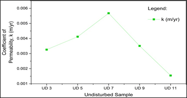
Fig. (17) shows the coefficient of consolidation (Cv) for each undisturbed sample of the clay layer. It shows the rate for each clay layer undergoing consolidation when subjected to an increase of pressure when a load is imposed. At the top layer, the efficiency for consolidation increases with the depth and has the highest reading at UD7 at a depth of 17 m but tends to reduce when it goes deeper to the UD11. This means the soil characteristics change when it goes deeper, and the efficiency for consolidation is becoming more difficult because of the clay particle being very cohesive.
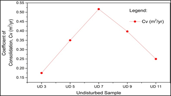
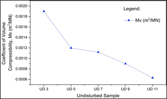
Fig. (18) shows the coefficient of volume compressibility (Mv) for each undisturbed sample in every clay layer. The trend for compressibility in the layer reduces with the depth given the difficulties for the air and water to discharge when the clay is subjected to the impact of loading. This can be summarised by saying that the success of a particular ground treatment method still depends on the behaviour of the subsoil to perform, as per the prediction.
| BH3 | Undistributed Sample | Depth (m) | Coefficient of Consolidation, Cv (m2/yr) | Coefficient of Volume Compressibility (m2/MN) | Coefficient of Permeability, k (m/yr) |
| 1 | UD 3 | 5.0 | 0.1750 | 0.0019 | 0.0033 |
| 2 | UD 5 | 11.0 | 0.3500 | 0.0012 | 0.0041 |
| 3 | UD 7 | 17.0 | 0.5167 | 0.0011 | 0.0057 |
| 4 | UD 9 | 23.0 | 0.3975 | 0.0009 | 0.0035 |
| 5 | UD 11 | 29.0 | 0.2500 | 0.0006 | 0.0015 |
CONCLUSION
This study has shown that various aspects and factors are involved in the performance of PVDs, some being attributable to kinks, smear effects and the construction of the embankment. In summary, these analysis methods showed that the predicted value was much higher than the actual site result. The field studies highlight the successful implementation of PVDs for ground improvement work in most soft soil areas which has accelerated the consolidation of soft soils and reduces construction time. Furthermore, the characteristics of the soft soil will become more complex as it goes more deeper. More soil investigation test and methods should be explored in future studies so the undisturbed samples will represent the actual nature of the soil underneath. The combination of simulation applications for the prediction process is a helpful indicator and guide that benefits geotechnical engineers.
CONSENT FOR PUBLICATION
Not applicable.
AVAILABILITY OF DATA AND MATERIALS
Not applicable.
FUNDING
This work was supported by the Fundamental Research Grant Scheme (FRGS) awarded by the Ministry of Education of Malaysia entitle ‘Enhanced Coalbed Methane Recovery Processes by Coupling Fluid Flow of Mukah-Balingian Coal Deposits’ with referral no. R.J130000.7851.5F371.
This work was supported by the Universiti Teknologi Malaysia Encouragement Research Grant (UTMER) awarded by Universiti Teknologi Malaysia entitle ‘Diagnosis of Alkali-Aggregate Reaction – Polarizing Microscopy and SEMEDS Analysis’ with referral no. Q.J130000.3851.19J79.
CONFLICT OF INTEREST
The authors declare no conflict of interest, financial or otherwise.
ACKNOWLEDGEMENTS
The author who has made substantial contributions to the work reported in the manuscript (e.g., technical help, writing and editing assistance, general support) but who do not meet the criteria for authorship are named in the Acknowledgements and have given us their written permission to be named. If we have not included an Acknowledgement, that indicates that we have not received substantial contributions from non-authors.

