All published articles of this journal are available on ScienceDirect.

Detection of Rockfalls on Tunnel Faces Using Extracted Moving Objects, Excavation Point Estimation, and Generation of Trajectory Images
Authors Info & Affiliations
Abstract
Background:
Tunnels are constructed at various locations for infrastructural purposes. During tunnel construction, industrial accidents have occurred due to rockfalls at tunnel faces. In addition, it has been confirmed that large rockfalls are precursors to tunnel collapses. Visual monitoring is currently used to detect such rockfalls. However, there are limitations to visual monitoring, and monitoring equipment is needed.
Objective:
In existing research, the inter-frame difference method of image processing and laser measurement methods have been proposed. However, there are difficulties in monitoring the entirety of the tunnel face using these methods. Thus, we propose methods that can overcome these difficulties and accurately detect rockfalls and identify where they occur.
Methods:
In this study, we propose a method for detecting rockfalls by combining the extraction of moving objects on a tunnel face and the estimation of excavation points. To identify the location of the rockfalls, rockfall trajectory images were generated.
Results:
Through experiments conducted during excavation, it was confirmed that the proposed method could correctly identify and detect only rockfalls in real time and identify the locations where they occurred.
Conclusion:
In this study, only rockfalls of 52 mm x 71 mm in size are detected in real time. It can enable workers to evacuate and prevent industrial accidents. In addition, by identifying the location of rockfalls, it is possible to know the danger level of the tunnel face.
1. INTRODUCTION
Tunnels are constructed in various places, such as through mountains, underground, and undersea, to form transportation networks and infrastructure facilities that are essential in daily life [1]. In Japan, the New Austrian tunneling method (NATM), which is often used in the construction of mountain tunnels and was first proposed by Rabcewicz between 1964 and 1965, is used more than 50% of the time [2-5]. In this method, collapses and rockfalls that occur on tunnel faces are encountered by workers in any geological structure [6]. In addition to excavation work done using heavy machines, there are many situations wherein workers approach such a tunnel face, resulting in industrial accidents due to rockfalls. In accidents caused by rockfalls, 6% of the victims die and 36% are injured for more than a month, which is deeply alarming [7]. Therefore, it is necessary to understand the shapes of tunnel faces and their continuously changing deformation behaviors to prevent industrial accidents. Accordingly, the Ministry of Health, Labor, and Welfare (MHLW) of Japan formulated a guideline and made it mandatory to assign people to monitor tunnel faces according to their sizes [8].
Besides just learning about rockfalls for industrial accident prevention, it is also necessary to understand the mechanisms behind their occurrences; four main mechanisms have been identified [9, 10]. First, rock fragments crumble from the tunnel face owing to discontinuities in the structure of the tunnel face. Second, quicksand flows from the tunnel face due to water inflow. Third, extrusions from the tunnel face are caused by earth pressure. Fourth, exposure of the ground to air changes the properties of the ground and causes collapse. Therefore, an understanding of rockfalls can, in turn, lead to a better understanding of ground conditions. In addition, it is necessary to understand rockfalls in relation to tunnel collapses. This is because small-scale rockfalls occur before the tunnel collapses. Thus, it is important to determine the intensity of rockfalls and the locations they occur to avoid such collapses.
In general, visual monitoring is applied to observe and analyze rockfalls. However, visual monitoring is limited in environments with heavy machines and a constant inflow and outflow of people. Therefore, research and development on tunnel face-monitoring devices have been actively conducted, and various methods have been proposed [11-19]. In this paper, methods for the detection of rockfalls will be presented. First, a system for measuring the extrusion displacement of a tunnel face using a laser rangefinder was proposed [16], under which the top of the tunnel face was constantly measured. When a change in depth greater than the preset threshold occurred, it was detected as rockfall. A laser rangefinder is unique in that it has high measurement resolution and can quickly detect the displacement of the measurement point. However, when tunnel faces were measured for research, the movement of heavy machines or the inflow and outflow of people could cause a displacement in the measured value above the threshold value, incorrectly detecting rockfalls. In addition, the measurement range was limited and a laser rangefinder was required for each measurement point. Second, a method using inter-frame difference and existing multi-frame tracking methods was proposed [17]. It captured a video of the tunnel face using an RGB camera. The video consisted of multiple still images per second; these images are called frames. The inter-frame difference method considered the differences in each frame image and extracted only the pixels that had changed. In the image-processing industry, this method is often applied to extract moving objects from videos. It tracks the moving object as it moves downward in the vertical direction over multiple frames. Accordingly, if the downward movement of the object was greater than a preset threshold, it was detected as rockfall. Compared to the method using a laser rangefinder, this method has the advantage of being able to detect rockfall from the area that appears in the image, rather than from a single measurement point in the detection range. However, if a person or heavy machine moved in a vertically downward direction, it could also be detected. Third, a method for monitoring designated areas along with the inter-frame difference method was proposed [18, 19]. The RGB camera was used to capture a video of the tunnel face, and the monitoring range was set in advance based on the still images. The moving objects extracted by the inter-frame difference method within the monitoring range were detected as rockfalls. To eliminate the incorrect detection of people and heavy machines, the system tracked moving objects that entered from outside the monitoring range and did not detect them. This method also has the advantage of being able to detect rockfall from the area identified within the image. However, the area of pixels that such objects passed through was set as the range to avoid detection, which led to the narrowing of the detection range. Thus, when people or heavy machines moved within the monitoring range, it was nearly impossible to identify the location of the rockfalls. Fourth, a method for measuring the displacement of a tunnel face using a TOF camera was proposed [20]. A TOF camera is a camera that irradiates an infrared light onto a subject and measures three dimensions based on the phase of the time it takes for the infrared light to hit the subject and for the reflected light to return. In other words, the problem of a single measurement point, which is a drawback of the laser rangefinder method, can be resolved by measuring the displacement of a tunnel face in three dimensions with a TOF camera. The problem is that the visible size of rockfall is highly dependent on the size of the tunnel face, and TOF cameras often have low resolution (640 x 480). Additionally, water absorbs the infrared light that a TOF camera emits, making it impossible to measure a tunnel face that includes spring water or water components. Furthermore, for the purpose of visualization of displacement, displacement analysis is performed by normalizing the data measured in mm to 0-255 gradation, which reduces the measurement resolution. Fifth, a method for measuring the displacement of a tunnel face using millimeter-wave radar was proposed [21]. Radar waves in the 79-GHz frequency band, which is among the radar waves used for maritime vessels and air traffic control, are irradiated onto the tunnel face, and the phase of the reflected radio waves that reach the tunnel face is analyzed to perform a three-dimensional measurement. With the same degree of measurement accuracy as laser distance, it is possible to measure the displacement of a tunnel face in three dimensions using radar waves. On the other hand, the azimuth resolution is 1.95 degrees, and the resolution is low (18×20). In addition, if the radar reflectivity of the measurement target is low, 3D measurement is difficult. Recent research on improving the azimuth resolution of millimeter-wave radar has shown that the azimuth resolution has improved to 0.6 degrees, and higher resolution is being pursued, but it is still far behind RGB images [22]. Methods utilizing measurement techniques can detect skin fall-off by instantly capturing the depth displacement of the tunnel face compared to image processing techniques using RGB images. On the other hand, it has low resolution, and detection is highly dependent on the geological structure of the tunnel face. Image processing technology detects by analyzing RGB images, so it is easy to achieve high resolution and can detect small two-dimensional rockfalls. However, whether or not it is possible to instantly detect rockfall is dependent on the computational cost and resources of the algorithm.
In view of the above observations, this study aims to detect rockfalls on an entire tunnel face during an excavation conducted by heavy machines, wherein the tunnel face is exposed and there is a high risk of rockfalls. In addition, the study aims to identify the locations where rockfalls occur in order to analyze the corresponding ground conditions so that similar resulting industrial accidents can be prevented.
2. MATERIALS AND METHODS
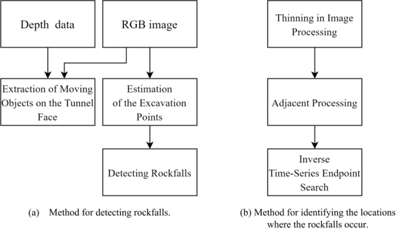
In this study, we propose a method for detecting rockfalls based on RGB-D data obtained by an RGB-D camera that combines tunnel face extraction and the inter-frame difference method with machine excavation point estimation using a single-color laser. RGB-D data includes a general RGB image and depth data collected from the RGB image of the object captured by the camera. In addition, we propose a method to identify the location of rockfalls using an inverse time-series endpoint search by generating a trajectory image of the rockfalls from the detected image. The algorithm for the proposed method is illustrated in Fig. (1).
2.1. Method of Detecting Rockfalls
2.1.1. Extraction of Moving Objects on the Tunnel Face
We focused on the specific locations where rockfalls were generated on the tunnel face and extracted moving objects on the tunnel face using RGB-D data obtained from RGB-D cameras. Three processes were used for this purpose.
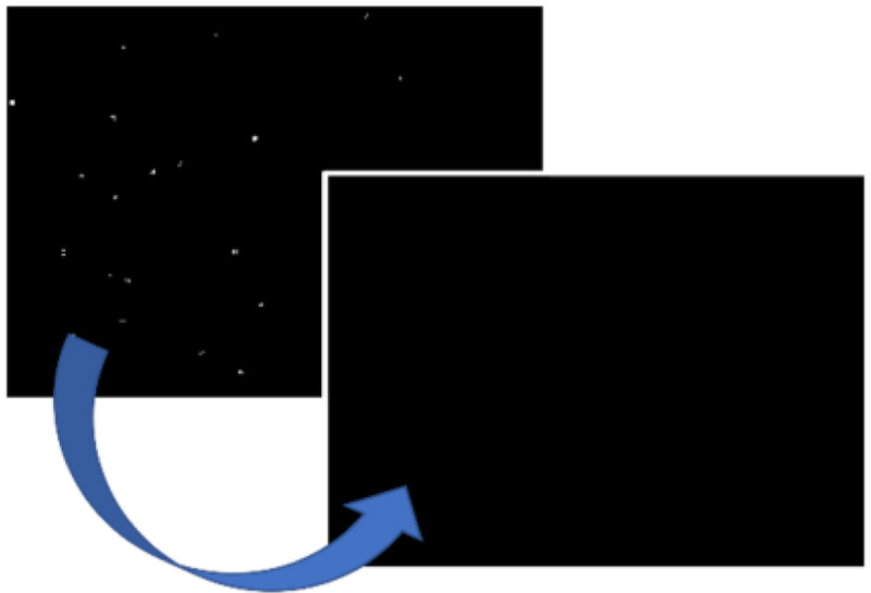
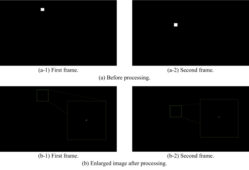
First, to extract moving objects from RGB-D data in the RGB images, we applied the inter-frame difference method used in conventional methods, as shown in Fig. (2). Since the inside of a tunnel is very dark, the extracted image of the moving object can have impulse noise, which is attributed to sparseness in the image pixels caused by a sudden disturbance in the image signal. To address this, denoising was applied using a commonly used median filter, as shown in Fig. (3). In the deionized image, all the moving objects including rockfalls, heavy machines, people, and excavated soil were extracted.
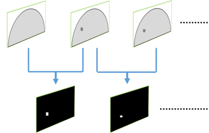
Next, when the camera was installed in advance, a 3D point cloud of depth data corresponding to the tunnel face was extracted in advance from the depth data. Since the tunnel face was approximated as a plane, a plane approximation equation was obtained for the extracted 3D point cloud against the RGB-D data of continuous frames to be captured using the least-squares method. Only the 3D point cloud that satisfied the obtained approximation equation was extracted from the depth data, as shown in Fig. (4). This was determined to be the point cloud of the tunnel face.
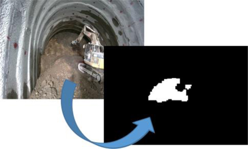
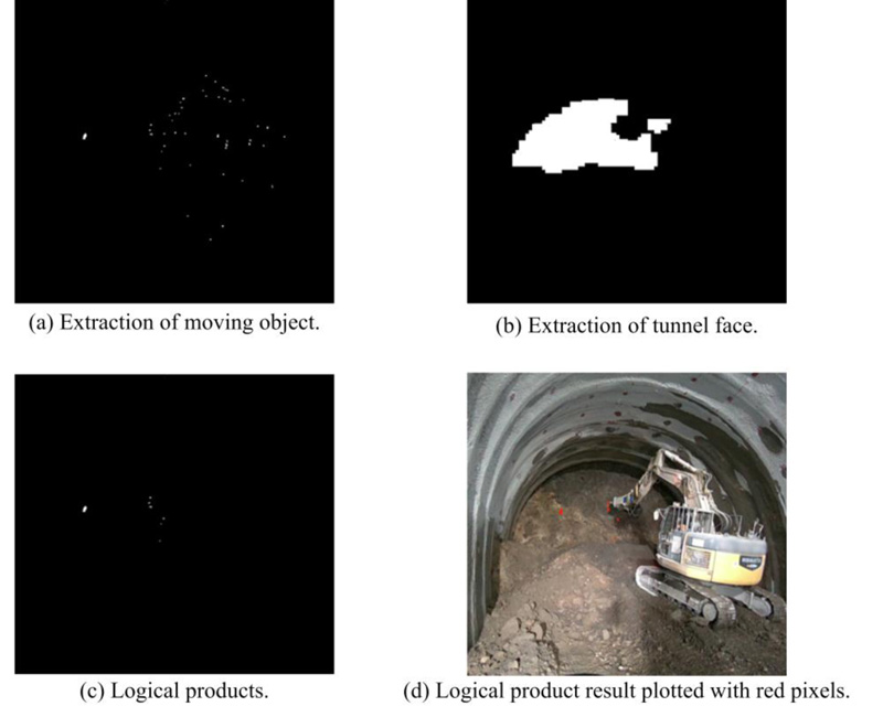
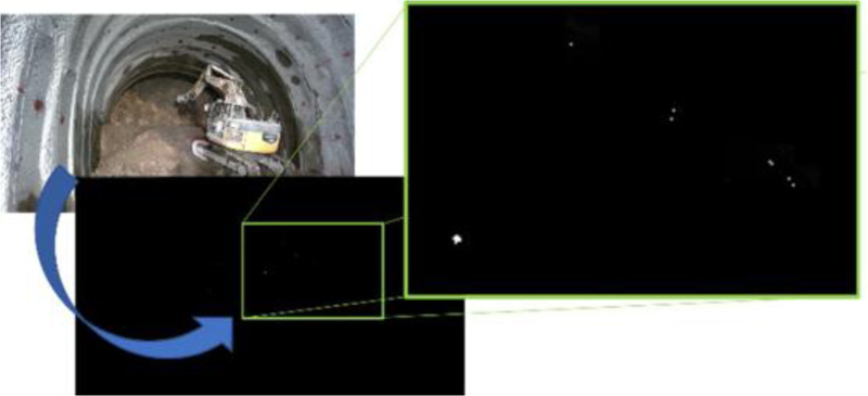
Finally, we computed the logical product of the extracted image of the moving object with the deionized image and the extracted image from the tunnel face. Thus, only moving objects on the tunnel face were extracted. Fig. (4) shows an example of this image. During machine excavation, the moving objects to be extracted on the tunnel face were rockfalls and excavated soil (Fig. 5).
2.1.2. Estimation of the Excavation Points
In 2.1.1, it was mentioned that the extracted moving objects on the tunnel face consisted of rockfalls and excavated soil. The excavated soil fell from the drill tip of a heavy machine. Therefore, as shown in Fig. (6), a single-color laser was installed to identify the tip of the drill in the heavy machine. During drilling, the single-color laser irradiated the tunnel face in contact with the drill tip, as shown in Fig. (7).
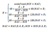
This irradiation was extracted from the RGB image and the HSV color space was used. The hue (H) in the HSV color space represented the colors in the hue ring, ranging from 0 to 360°. The RGB color space of the RGB image was converted into the HSV color space, as shown in Fig. (8).
Using the hue, 4-connected-component labeling was applied to the mask image from which the color of the laser pointer was extracted. The area of each labeled component was then calculated, as shown in Fig. (9). The element with the largest value corresponded to a single-color laser in the RGB image. In other words, the coordinates of the center of gravity (x,y) were excavation points. As shown in Fig. (9), the pixels in the red frame corresponded to this category. Equation (1) shows the equation that converted each pixel of the RGB image to the hue of the HSV color space:
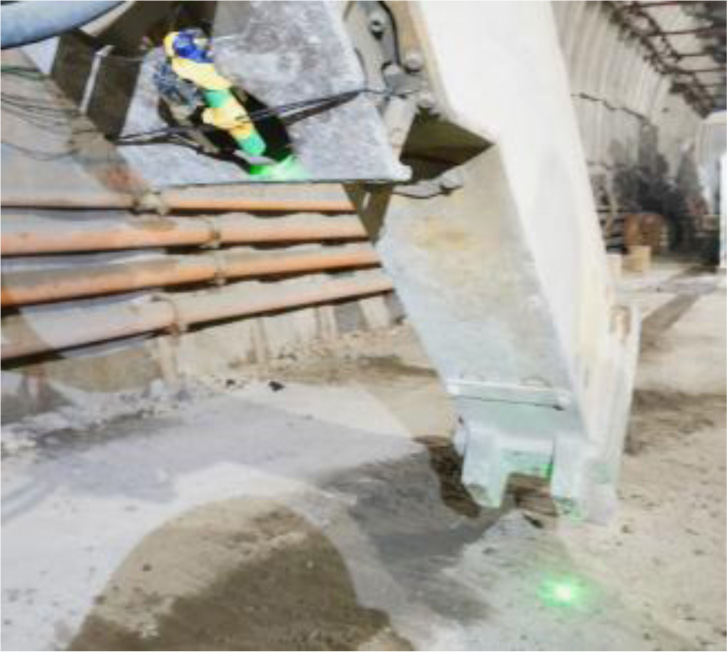
Fig. (7). Irradiation of the tunnel face in contact with the drill tip.
 |
(1) |
2.1.3. Detecting Rockfalls
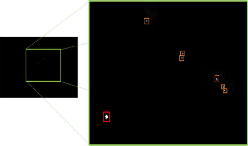
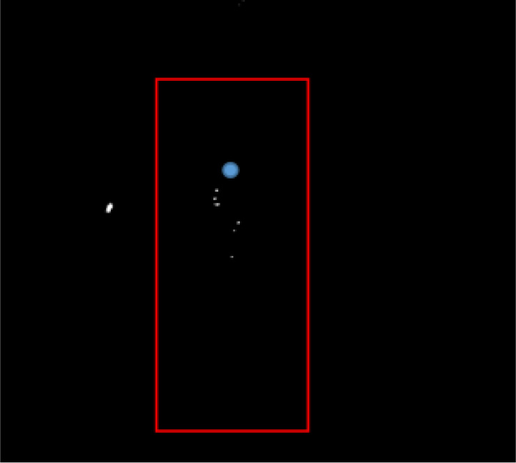
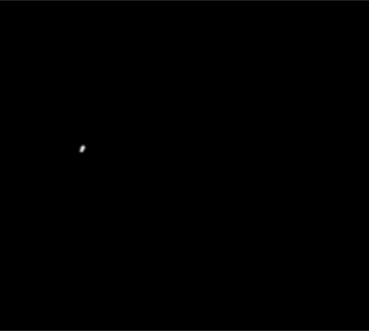
For the extracted image of the moving objects on the tunnel face mentioned in 2.1.1, the range (red frame) wherein the excavated soil was to be removed as specified, based on the coordinates of the excavation point (blue point) estimated in 2.1.2, as shown in Fig. (10). By removing pixels in the specified range, only the rockfalls were detected, as shown in Fig. (11).
2.2. Method for Identifying the Locations Where Rockfalls Occurred
In 2.1, images of rockfalls were labeled and stored in a continuous time-series frame image for each action until the rockfalls occurred. For each action, a process was applied to identify the location of the rockfalls. By applying this process to all the actions, it was possible to identify all the locations where rockfalls occurred.
2.2.1. Thinning in Image Processing
The continuous time-series image of a detected rockfall, as mentioned in 2.1, was converted into a 1 px line image by the four-neighborhood segmentation process using Zhang-Suen's method [23]. Thus, even when multiple rockfalls occurred in the vicinity of one another simultaneously, they could be represented as separate pieces of pixel information as shown in Fig. (12).
2.2.2. Adjacent Processing
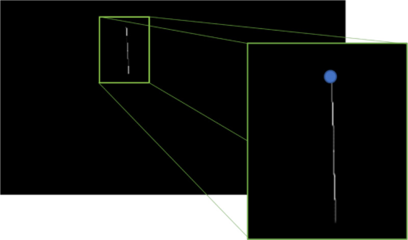
Adjacency processing was applied to the continuously time-series image after it had been thinned, as indicated in 2.2.1, between each thin line's endpoint in its own frame and each thin line's endpoint in the frame before it that had the shortest Euclidean distance. In other words, a line was drawn between the endpoints. This process generated a trajectory image of the rockfalls. Fig. (13) shows the trajectory image generated using the resulting image given in Fig. (12).

2.2.3. Inverse Time-series Endpoint Search
We applied the labeling process to the generated trajectory image, mentioned in 2.2.2, as shown in Fig. (14). For labeling, the endpoint (blue point) that had the minimum y-coordinate value in the image coordinate system was located. In other words, the endpoints were searched in the reverse chronological order. The coordinates of the endpoint image obtained by this process were used to identify the location of the rockfalls.
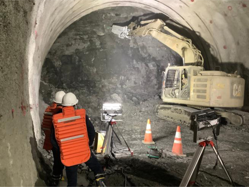
3. EXPERIMENTAL
To confirm the effectiveness of the proposed method, an experiment was conducted in an expressway tunnel that was under construction. It was also confirmed that the proposed method could detect rockfalls and identify the locations where the rockfalls occurred during machine excavation work.
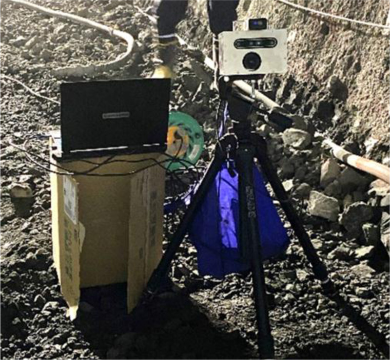
3.1. Equipment Used in the Experiment
The detection device was created using a commercially available RGB camera, a depth camera, and a computer. Images of the device are shown in Fig. (15), and the specifications of each camera, computer, and single-color laser are listed in (Tables 1-5).
| Model number | VCXU-65C.R |
| Resolution | 1536 × 1024 px |
| Exposure time | 1500 μs |
| Gain | 3.98 dB |
| FPS | 30 fps |
| Model number | LM5JCM-V |
| Focal length | 5 mm |
| F value | F2.8 |
| Angle of view | 82.4° × 63.9° |
Table 3.
| Model number | Intel RealSense Depth Camera D455 |
| Depth technology | Active IR stereo |
| Resolution | 1280 × 720 pixels |
| Angle of view | 86° ×57° (±3°) |
| Exposure time | 3300 μs |
| Gain | Auto |
| FPS | 30 fps |
| OS | Windows 10 Professional |
| CPU | Intel Core i7-10750H |
| RAM | 32 GB> |
| Model number | LPG350 |
| Laser wavelength | 532 nm |
| Laser power | 1 mW |
4. RESULTS AND DISCUSSION
4.1. Experimental Results
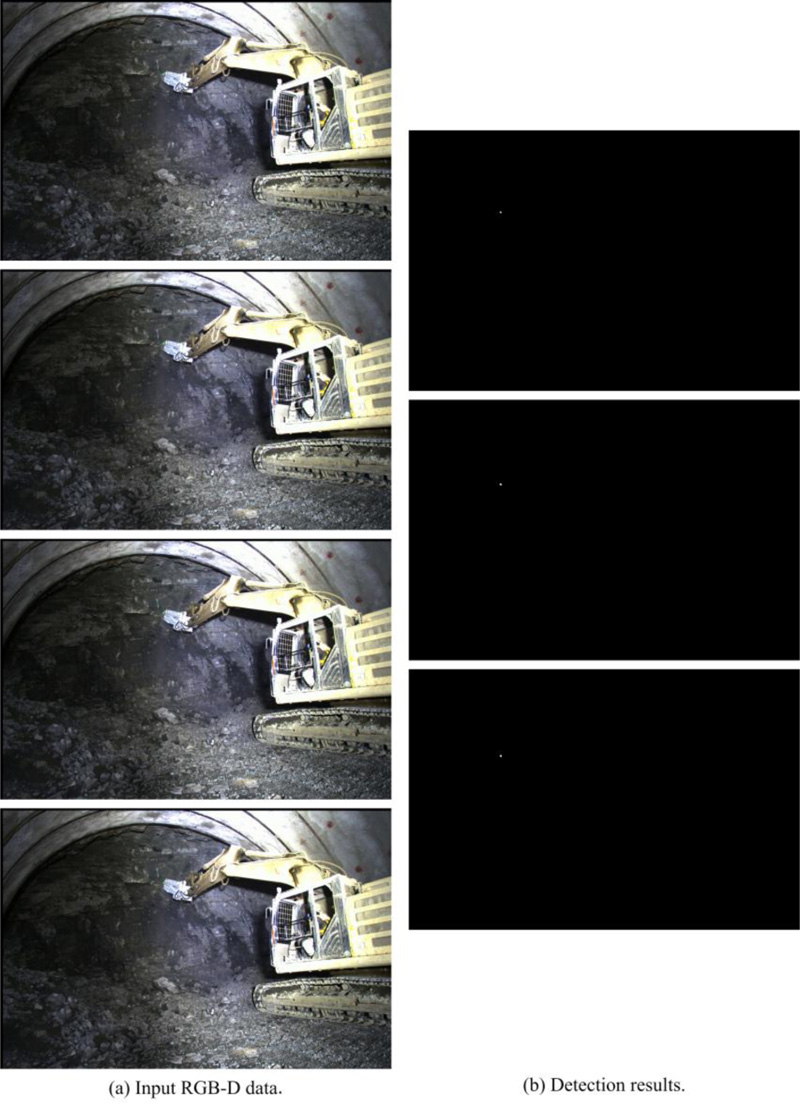
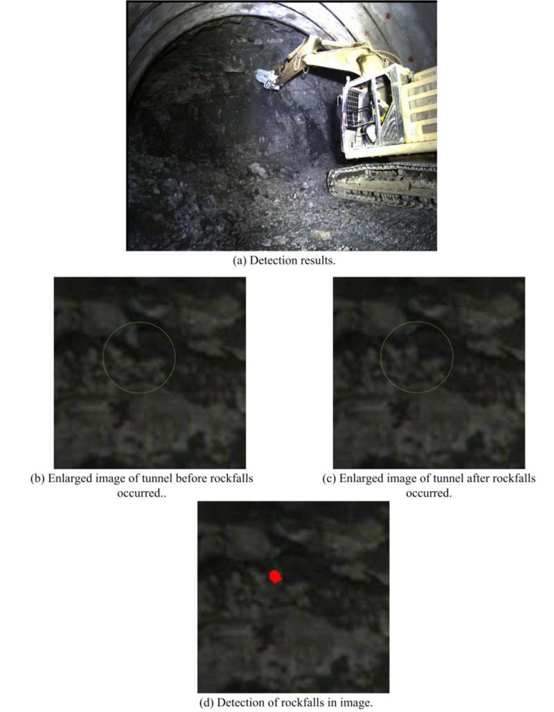
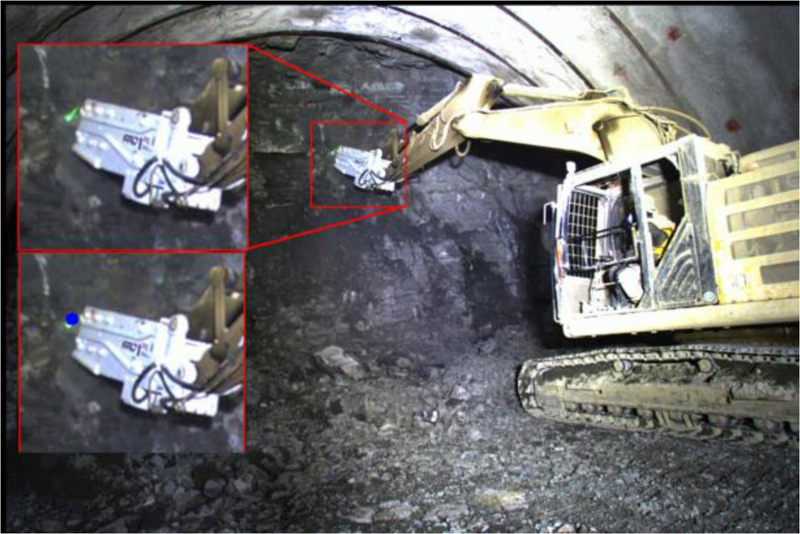
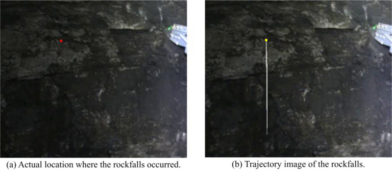
Fig. (17) shows the rockfall detection results in a series of captured frame images. Fig. (18) shows the resultant image with the detected falling rock pixels colored in red, the enlarged image of the detected area, and the detected frame images of the tunnel face before and after the rockfall occurred. Fig. (19) shows the estimated position of the single-color laser used to estimate the excavation point, colored with blue dots. Table 6 shows the processing time required for detecting the rockfalls. In Fig. (20), the areas where the rockfalls actually occurred are represented by red pixels, the specified coordinates determined by the proposed method where the rockfalls occurred by yellow dots, and the trajectory by white lines.
| Maximum | 24.94 ~ 25.43 ms |
| Average | 31.62 ms |
| Confidence interval (95% CI) | 24.94 ~ 25.43 ms |
5. DISCUSSION
Fig. (19) shows that the single-color laser and its estimated position are coincident. Therefore, it was confirmed that the rockfalls and excavated soil could be separated. From Figs. 17 and 18), it was confirmed that the proposed method could only detect rockfalls by identifying the excavation location in an environment with various moving objects. The conventional method using a laser rangefinder could only capture depth changes at a single point, but the proposed method makes it possible to detect rockfall in two dimensions on the tunnel face. And by extracting the tunnel face using depth data for each frame, the problem of narrowing the monitoring area and detecting heavy machines is solved. The pixel size of the rockfalls in the image of the detection result was 40 pixels, which is 52 mm × 71 mm based on the spatial resolution of the image, which could detect rockfalls. The spatial resolution size per pixel at a distance of 10 m between the tunnel and the camera in the experiment is 10 mm x 9 mm. The proposed method uses a median filter to remove noise, and blocks of pixels smaller than 15 pixels are removed. Therefore, the detection limit size in this experiment is blocks of 15 pixels, which is 30 mm x 44 mm. If the distance between tunnel cameras increases, the spatial resolution will decrease, and the detection limit size will increase. Also, the larger the filter size, the larger the detection limit size, and vice versa. Increasing the resolution of the camera improves spatial resolution and allows smaller objects’ detection, but increases computational cost. To capture smaller rockfalls, it was necessary to increase the resolution of the camera. The brightness of the light illuminating the tunnel face where the experiment was conducted, was approximately 80 lx, indicating a dark environment. In general, images taken with a high-resolution camera in a dark environment will contain a significant amount of noise. Therefore, the noise cannot be completely removed by the median filter and may also be detected as falling rocks. In other words, the detection limit size depends on the distance from the camera to the tunnel face, the resolution, and the filter size of the median filter. In addition, when the shooting distance is extended, the accuracy of the depth data measurement is expected to affect the accuracy of tunnel face extraction. Experiments have confirmed that adequate tunnel face extraction can be achieved at a shooting distance of 10 m. However, when the distance exceeds 10 m, just a portion of the tunnel face may be extracted . Therefore, it is considered necessary to change the equipment used to acquire depth data according to the shooting distance. For example, LIDAR and TOF cameras could be considered, but their equipment is more expensive and has a lower resolution than the stereo camera used in the experiment.
During excavation, the detection of rockfalls needed to be transmitted in real-time to the inside of the tunnel. The video was captured and processed at 30 fps; each second consisted of 30 frames of still images. Since the proposed method used the inter-frame difference method, it was necessary to apply this method before the next frame was acquired. Therefore, it needed to be proved that the proposed method could be applied to real-time processing within 33 ms. As shown in Table 6, the average processing time was 25.19 ms and the maximum processing time was 31.62 ms, which means that the processing time was within 33 ms. The confidence interval (95% CI) was 24.94 ~ 25.43 ms, which means that real-time processing with high accuracy was achieved. In other words, the ability to detect in real-time enables workers to evacuate quickly, resulting in the prevention of industrial accidents. In addition, the proposed method uses a consumer-used camera and a personal computer to achieve instantaneous detection, which is an advantage of measurement technology-based methods.
Investigating the sizes of the rockfalls that contributed to industrial accidents and tunnel collapses was vital, as was determining which rockfalls could be recognized based on size. A report on industrial accidents [7] showed that they occurred because of relatively large rockfalls with an average size of 1000 mm x 600 mm, showing that the proposed method could only detect smaller-sized rockfalls. However, it is generally believed that sporadic occurrences could cause a collapse when it comes to rockfalls as a precursor to tunnel collapse. However, there is a factor where such a decision is dependent on the workers' intuition and years of expertise. Rockfalls from the top of the tunnel face have been linked in the field to pressure from the tunnel's top and extrusion displacement, among other factors. Determining the frequency and amount of rockfalls from the tunnel face's top is therefore necessary. (Fig. 20) shows that the location where the rockfalls occurred and those identified by the trajectory generated by the proposed method were the same, proving that the location where the rockfalls occurred could be properly identified. It has been possible to determine the magnitude and location of the occurrences by generating trajectory photos and detection result images. However, there is a problem that sufficient data for quantitative evaluation has not been obtained. Therefore, it is conceivable to evaluate the risk of tunnel collapse by collecting long-term experimental data from various construction sites and analyzing the relationship between the size, location, and frequency of rockfalls that occur and the geological structure of the tunnel face. For instance, neural network-based algorithms [25] and methods for calculating excavation energy from tunnel face images [24] are both used in tunnel face evaluation studies. By using these techniques as explanatory factors or input data, there are applications that might result in assessments that are more accurate.
CONCLUSION
In this study, we propose a method for detecting rockfalls based on RGB-D data obtained by an RGB-D camera, which combines tunnel face extraction and inter-frame difference methods with machine excavation point estimation using a single-color laser. In addition, we propose a method to identify the location where the rockfalls occurred using an inverse time-series endpoint search by generating a trajectory image of the rockfalls from the detected image.
Conventional methods have the problem of incorrectly detecting heavy machines and people as rockfalls; however, by focusing on the fact that rockfalls occur on tunnel faces, we attempted to identify and detect rockfalls correctly. The experimental results confirmed that only rockfalls were detected. During excavation, the detection of rockfalls needed to be transmitted in real-time to the inside of the tunnel. The average and maximum processing times were 25.19 and 31.62 ms, respectively, which means that the processing time was within 33 ms. The confidence interval (95% CI) was 24.94 ~ 25.43 ms, which means that real-time processing with high accuracy was achieved. In other words, the ability to detect in real-time allows workers to evacuate quickly, resulting in the prevention of occupational accidents.
It was necessary to investigate the sizes of rockfalls that had impacts on industrial accidents and tunnel collapses to determine the necessary sizes of rockfalls that could be detected. Industrial accidents occurred due to relatively large rockfalls with an average size of 1000 mm x 600 mm, showing that the proposed method could detect smaller-sized rockfalls. It is generally accepted that sporadic occurrences could cause a collapse when it comes to rockfalls as a precursor to tunnel collapse. One aspect is that these decisions are made based on the workers' intuition and years of experience. Rockfalls from the top of the tunnel face have been linked in the field to pressure from the tunnel's top and extrusion displacement, among other factors. Therefore, it is necessary to determine the number of times and the size of rockfalls from the top of the tunnel face. The trajectory generated by the proposed method and the location of the rockfalls coincide, indicating that the location of the rockfalls is properly identified.
We believe that the proposed method can be used to collect data and quantitatively evaluate the sizes of rockfalls that result in tunnel collapses. Future research could examine the relationship between the geological structure of the tunnel face and the magnitude, location, and frequency of rockfalls. For instance, approaches for calculating excavation energy from tunnel face photos and methods utilizing neural networks are used in tunnel face evaluation research. By using these techniques as explanatory factors or input data, there are applications that might result in even more accurate assessments.
LIST OF ABBREVIATIONS
| NATM | = New Austrian tunneling method |
CONSENT FOR PUBLICATIONS
Not applicable.
AVAILABILITY OF DATA AND MATERIALS
Data underlying the results presented in this paper are not publicly available at this time but may be obtained from the authors upon reasonable request.
FUNDING
None.
CONFLICT OF INTEREST
The authors declare no conflict of interest, financial or otherwise.
ACKNOWLEDGEMENTS
This study is the result of joint research between Tokyo City University and Tokyu Construction Co., Ltd. We would like to express our sincere gratitude to Tokyu Construction Co., Ltd. for their cooperation in securing the experimental site, arranging the equipment, and providing guidance on tunnel construction.

