All published articles of this journal are available on ScienceDirect.

An Overview of Theoretical Analysis Method for Composite Repaired Pipelines
Authors Info & Affiliations
Abstract
Pipelines are an important way of transportation for gas, oil and other petroleum products, and they are typically exposed to a harsh environment, leading to corrosion defects, cracks, leakage, dents and so on. A composite repair system is a favourable repair system for defective pipelines owing to its high strength, lightweight, cost-effectiveness, elimination of explosion and so on. Considerable research has been carried out on the composite repaired pipelines. However, there are still many issues and challenges to overcome in order to improve the existing repair designs. Therefore, this paper aims to review the theoretical analysis method for pressurized composite repaired pipelines. A better understanding of the mechanisms of stress distribution will benefit the development of composite repaired pipelines. They are mainly summarized into three models, namely the one-layer model, two-layer model, and three-layer model, which are all based on the thin-walled theory and the Lame approach. Both the advantages and disadvantages of these theoretical models are highlighted. Finally, in the conclusion section, the current research gap and future scopes of study in the theoretical analysis are also presented to provide insight into a more effective design philosophy for composite repaired pipelines.
1. INTRODUCTION
Since the 1940s and 1950s, steel pipelines have become a means to transport oil and gas products [1]. Until now, there are millions of kilometers of metallic pipes laid throughout the world. Therefore, steel pipelines have been recognized as the most effective and safest way to deliver oil and natural gas [2-4]. After long service histories, some sections of high-pressure pipelines may experience corrosion, cracks, leakage, and dents [1, 5-7]. According to previous studies, corrosion is one of the main causes of damage in pipelines, with an average occurrence time of 0.2 years [8-12]. Furthermore, external corrosion is the most common type of damage [8, 9, 13-16]. Therefore, the rehabilitation of the defective pipeline is an important issue to be addressed using all possible repair techniques in order to re-establish the operating capacity of the pipelines [17-22].
Compared to conventional steel repair techniques, fiber-reinforced polymeric (FRP) composite repair systems have been widely applied in repairing corroded metallic pipelines because of their high strength and stiffness, lightweight, corrosion prevention, cost and time-saving, elimination of the explosion risk, un-disturbing fluid transmission, etc [15, 18, 23-27]. Therefore, more and more research institutes and companies are developing various composite repair systems, aiming to make the best selection depending on the specific situation. Despite the many advantages of composite repaired pipelines, several issues and challenges still need to be further studied. These problems include conservativeness of composite repair thickness in the existing closed-form solutions, negligence of the role of infill materials and combination of defect geometries, dangers of burst tests and accuracy of numerical analysis towards the composite repaired pipelines [28-36]. Regarding to the above issues, some review papers have been published, but the overview of the theoretical analysis towards the composite repaired pipeline is not comprehensively covered.
Especially for the research method, many researchers investigated the behaviors of composite repaired corroded pipelines using lab and field experiments, numerical simulations, and theoretical derivations [1, 21, 25, 29, 37-50]. In comparison to experimental burst tests and finite element analysis (FEA), the theoretical analysis method is another efficient approach to analyzing and evaluating the effects of the composite repair system. This review paper mainly summarizes and reviews the theoretical analysis model of pipeline repair proposed by previous researchers. These analytical methods were conducted to further study the composite repaired corroded pipelines incorporating many factors, such as composite repair thickness, defect sizes, infill materials, plastic deformation of steel, failure pressure, etc. Based on the various factors, they can be summarized into three models, which are the one-layer model, the two-layer model and the three-layer model. Generally, the one-layer model is taken as a base model, which helps to develop another two models. As for the two-layer model, there is no consideration about the effects of defect geometries and infill materials. Regarding to the three-layer model, there is not special for three-layer thin-walled model and taking account the infill materials and defect geometries. Based on these studies, the theoretical analysis method towards the composite repaired pipelines can be optimized by improving their shortcomings.
In addition, several companies in the oil and gas pipeline industry are keen in reducing the usage of composite wrap since it can directly reduce the repair cost of repair materials and other issues related to usage of composite wraps. It will provide a practical theory and guideline in pipeline rehabilitation.
2. DETERMINATION OF COMPOSITE REPAIR THICKNESS
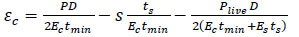
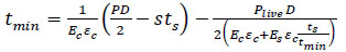
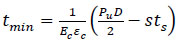
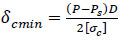
When using a composite repair system, the composite repair thickness needs to be calculated first, which is based on the existing standards and codes. Currently, the most remarkable development in composite repair standards is the development of ASME PCC-2-part 4, Non-metallic and Bonded Repairs and ISO/TS 24817, Composite Repairs for Pipework, implemented in the industry to repair a damaged pipe [51, 52]. They were developed in order to provide guidelines for the safe designing of the composite repair system of a damaged pipe, which can guarantee structural integrity. These standards refer to a wide range of pipe defects, such as general and local wall thinning, pitting, gouges, cracks and so on. Therefore, an accurate composite repair thickness is an important parameter for better performance of composite repair systems. A well-defined composite repair thickness determination is proposed based on the ASME PCC-2 and ISO 24817 standards. According to Eq. (1), the minimum thickness of the repair (Eq. 2) can be derived from it when the pipe sustains the internal design pressure and live pressure, that is, the internal operation pressure in the pipe at the time of repair application.
 |
(1) |
 |
(2) |
Where P is design pressure, Plive is the live pressure, Ec and Es are the composite and steel modulus of elasticity, respectively, ts is the minimum remaining pipe wall thickness, tmin is the minimum required thickness of the composite layer, D is the pipe diameter, εc is the composite allowable circumferential strain, and s is the specified minimum yield strength (SMYS) of the pipe.
Assuming the repair of the metallic pipe is done at zero pressure (Plive=0), Eq. (2) becomes:
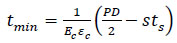 |
(3) |
Eqs. (1 and 2) indicate that the thickness of composite repair not only depends on Ec, Es, εc, ts and D, but also P, Plive and s (SMYS). The aim of the design is to calculate a composite repair thickness that can increase the strength of the defected pipe so that it can withstand yield pressure (Pf) and ultimate pressure (Pu). With the internal pressure increasing, the internal pressure P can be classified into three cases:
Case 1: P = Plive
Case 2: Plive < P < Pf
Case 3: Pf < P <Pu
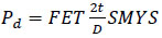
Hence, according to different design purposes, the calculated minimum repair thickness from Eq. (3), the authors can choose different internal pressures. For instance, a failure pressure (experimental burst pressure) was assumed in the research work by Duell (i.e. P=44MPa) [29]. Additionally, the test pressure can also be determined by the following Eq. (4) used by Lim (i.e., Pf=24.76MPa), aiming to demonstrate the integrity of the composite repair up to the yield of the original pipe [37, 53]. In some cases, the design pressure Pd is calculated using Eq. (5) as per ASME B31.4, considering a design factor of 0.72 [30, 54]. This pressure Pd is also referred to as the maximum allowable working pressure (MAWP).
 |
(4) |
 |
(5) |
where F is a design factor, E is a longitudinal joint factor, and T is a temperature derating factor. In most cases, FET often adopts the value of 0.72.
Thus, no matter the design pressure using Pu, Pf or Pd, the composite repair thickness can be calculated by Eq. (3) for a different purpose. From Eq. (3), it is noted that ASME PCC-2 and ISO/TS 24817 standards both neglect the defect size, putty contribution, and strain-hardening effect.
Additionally, in order to investigate the effects of the live pressure Plive, Saeed et al. presented that the composite repair thickness is independent of live pressure, which was validated through analytical equations and the finite element method (FEM). Based on the findings, a proper modification was proposed to the existing equation. Eq. (6) provides a correct estimate for the composite repair thickness, which shows that even though the live pressure is operated on the pipe, there is no influence on the hoop strain of the repair laminate [55].
 |
(6) |
In Eqs. (1 to 3), the definition of ‘s’ is different between the two codes. ASME PCC-2 identifies it as a specific minimum yield stress allowing pipes to yield [51], while ISO 24817 does not allow pipe yielding and takes ‘s’ as allowable stress, which is less than the yield stress of the pipe [52]. It implies that the composite repair thickness calculated as per ASME PCC-2 is lower than ISO 24817, which means ISO 24817 is more conservative for most of the design situations when the live pressure and the wall loss thickness are larger [30].
Moreover, an accurate composite repair thickness was observed where values from numerical modelling are less than that from the standards (ASME PCC-2 and ISO 24817) for the same design pressure [30, 32, 54]. For example, the minimum composite repair thickness was found to be 4.57 mm according to the ASME PCC-2 standard and 3.1 mm obtained by the FEM for the corroded pipeline reinforced with a carbon composite repair system [29]. It implies that there is an excessive composite wrap calculated by Eq. (3), which leads to an increase in the repair cost. Therefore, in order to obtain an accurate composite repair thickness and reduce expenses, the defect geometry (depth, width and length), the strain hardening of the steel pipe, and the infill materials should be taken into consideration to make further improvements to the existing design codes. Based on the existing problems, several researchers set out to optimize and modify the current standards of the design equation and the selection of material properties of putty and composite [36, 43, 56-58]. Owing to that, this paper will further review the composite repaired pipelines using theoretical analysis methods.
3. THEORETICAL ANALYSIS
3.1. One-layer Model
Thin-walled and thick-walled cylinders determined by a wall thickness-to-internal radius ratio are two common types of pipelines that are mainly used in the onshore and offshore industry to deliver gas and oil. Regarding the cylindrical pressure vessels, there are two methods to calculate and evaluate the stress in the hoop and axial direction, respectively.
For thin-walled cylinders, the thin-walled method is the most common solution, which is based on a simple mechanical approach and only applicable to pipelines with a wall thickness-to-internal radius ratio of less than about 1/10 [59]. Based on the thin-walled method, the circumferential hoop stress and longitudinal axial stress of the closed-end thin-walled cylinder can be expressed as follows (Eqs. 7, 8):
 |
(7) |
 |
(8) |
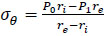
Where σθ (MPa) is the hoop stress in the circumferential direction and σa (MPa) is the axial stress in the longitudinal direction. Pi (MPa) is the applied internal pressure, D (mm) is the external diameter of the cylindrical vessels, and t (mm) is the original thickness of the pipe.
In the case of the thin-walled cylinder with inner radius ri and external radius re subjected to an internal pressure P0 and an external pressure P1, the hoop stress σθ can be simply expressed as follows [60] (Eq. 9):
 |
(9) |
The other method is the Lame approach [61], which is applied to any cylindrical pipe with any wall thickness-to-internal radius ratio. Huang et al. proved that the relative error of hoop stress calculated by Eqs. (7 and 10) is below 5% when the thin-walled cylinder is under internal pressure [62]. Equations for the hoop stress and axial stress of a thick-walled pipe were developed by Lame in the early nineteenth century [63, 64], and the Lame approach is usually referred to as the method for thick-wall cylindrical pressure pipes (Eq. 11).
 |
(10) |
 |
(11) |
Where A and B are constants that depend on boundary conditions.
Together, these studies provide important insights into the thin-walled and thick-walled pipes, which can be seen as a one-layer model. Moreover, most of the other theoretical models are based on the one-layer model from the original thin-walled and thick-walled pipes theories. However, the one-layer model is just applicable to cylinders made of one material. As for the composite repaired pipelines, the corroded pipelines are wrapped by composites and cannot be taken as a one-layer model. Therefore, there is another way to further study the corroded pipeline repaired by composites.
3.2. Two-layer Model
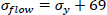
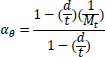
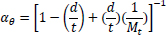
Based on the equations of thin-walled and thick-walled pipe, the composite repaired pipe can be considered as a two-layer model. Two-layer composite repaired pipes consist of corroded steel pipe and composite sleeve. As for the corroded steel pipe, there are two methods to build the analytical model. One method is to take the intact pipe as an inner layer first and then introduce a damaged factor (αθ) to account for the local defect of the pipe [56, 65, 66], the other method is only to consider the remaining wall thickness of the corroded pipe [67]. There are many criteria available to calculate the damaged factor. The most widely used criteria to evaluate the corroded pipelines under internal pressure are ASME B31G, RSTRENG 0.85, and DNV [60]. Apart from the above criteria, there are others, which are shown in Table 1. Every criterion has a different bulging factor and flow stress for the same defect geometry [68-70]. Meanwhile, Table 1 presents the comparison of failure pressures based on different criteria [38]. It can be seen that RSTRENG 0.85 modified criterion is much closer to the experimental failure pressure of 36.28 MPa [54, 56, 38], while the Sims pressure vessel criterion has a large deviation. Moreover, the predicted failure pressures are all conservative when using the damaged factors. Therefore, the criterion selection for the damaged factor is an open question and needs to be further investigated [38, 56, 71].
| Criteria | Bulging Factor | Damaged Factor/Remaining Strength | Flow Stress | Failure Pressure (MPa) |
|---|---|---|---|---|
| ASME B31G | 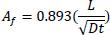 |
 |
 |
30.95 |
| RSTRENG 0.85(Modified ASME B31G) | 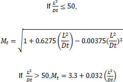 |
 |
 |
35.17 |
| DNV | 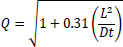 |
 |
 |
28.47 |
| Ritchie and Last criterion | 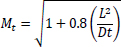 |
 |
 |
27.78 |
| Chell limits load analysis | 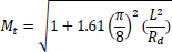 |
 |
 |
28.47 |
| Sims pressure vessel criteria | 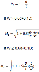 |
 |
 |
13.03 |
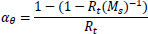
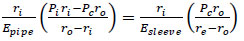
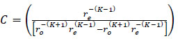
Similarly, Freire et al. proposed a simple method to analyse the two-layer model (Fig. 1) by neglecting the corroded part at first and then introducing a factor C that takes into account the corrosion damage or defect in the pipe [72]. Although the author did not derive an equation used to determine the composite repair thickness, he provided a good idea for further research on determining the composite repair thickness. The derivation process is as follows (Eqs. 12-14) :
3.2.3. After Yielding
 |
(14) |
Where C is the Nondimensional stress modification term derived from the DNV RP-F101, which takes into consideration the defect size and the strain-hardening effect but neglects the contribution of putty material. As a result, it will directly affect the determination of composite repair thickness.
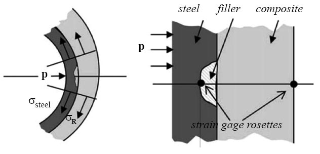
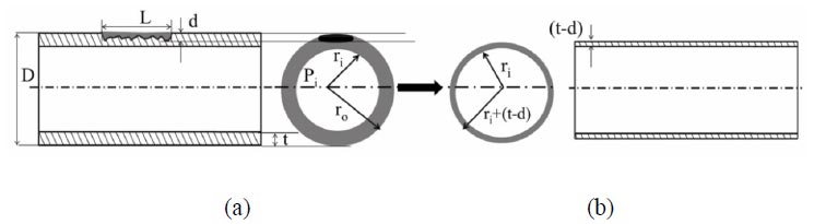
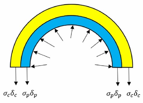
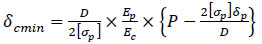
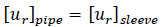
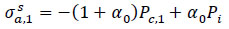
Additionally, another basic model of composite repaired pipe includes considering only the remaining wall thickness of the substrate, which is presented in Fig. (2). It is assumed that the corroded pipe is repaired with a thin-walled composite, and the behaviours of pipe and composite are both idealized to be elastic. The pipe-composite wrap is modelled as two concentric thin-walled cylinders subjected to internal pressure (Pi). The hoop stresses are distributed uniformly in the pipe and composite, and the hoop strains of the pipe and the composite are equal [67].
According to the force equilibrium conditions shown in Fig. (3), the internal pressure Pi can be shared by the defective pipe and the composite laminate. Hence, force shared by defective pipe and composite laminate = total force exerted on the repaired pipe (Eq. 15).
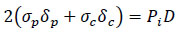 |
(15) |
Where σp (MPa) is the hoop stress of the pipe wall, δp (mm) is the remaining wall thickness of the pipe, σc (MPa) is the hoop stress of the composite layer, δc (mm) is the composite repair thickness, Pi (MPa) is the internal pressure of the pipe, and D (mm) is the inner diameter of the pipe.
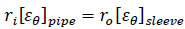
It is assumed that the strain in the steel pipe is equal to that in the composite laminate due to neglecting the variation of the wall thickness. Therefore, from the strain compatibility relationship (Eqs. 16, 17):
 |
(16) |
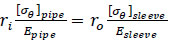
The hoop stress for a pipe within the elastic range is:
 |
(17) |
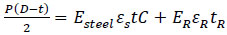
If the steel pipe is not allowed to yield, shown in Eq. (18), the composite repair thickness can be calculated by Eq. (19), where [σp] is the allowable stress of the pipe. However, the results need more composite material and lead to a higher conservative and repair cost.
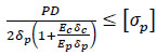 |
(18) |
 |
(19) |
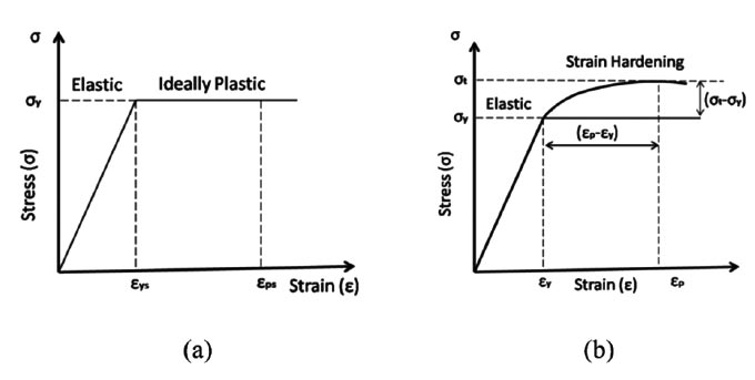
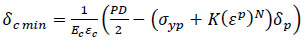
With the internal pressure increasing, the ultimate pressure will be higher than the yield pressure. There are two types of constitutive models for the steel pipe considering the plastic behaviour: the Elastic-Perfectly Plastic model and the Elastic-Plastic Deformation model (strain hardening), as shown in Fig. (4). Additionally, as stated by Lim, the author compared the infill material models using finite element analysis, including elastic only, bilinear-compression, bilinear-tensile, and tensile elastic-perfectly plastic. It was found that only the tensile elastic-perfectly plastic model was in good agreement with the burst pressure of 33MPa with an error margin of 3.73% [37]. Therefore, the constitutive models of materials play an important role in analysing the behaviour of composite repaired pipelines.
Based on the elastic-perfectly plastic model shown in Fig. (4a), it is assumed that the additional pressure over the yield pressure is only sustained by the composite laminate due to the pipe no longer resisting any higher pressure above yield. It means that the stress of the steel is constant with the strain increasing, as the force is sustained by the composite only. Therefore, force shared by defective pipe and composite laminate = total force exerted on the repaired pipe.
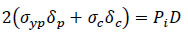 |
(20) |
Where σc=Ecεc, thus the above Eq. (20) is given as:
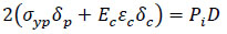 |
(21) |
Eq. (21) can be rearranged and the composite thickness is given as:
 |
(22) |
Where Ps=2δpσyp/D, σyp is the yield strength of the steel pipe.
It should be noted that the difference between Eqs. (19-22) suggests considering the steel plastic deformation or not.
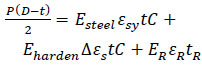
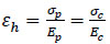
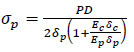
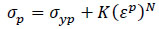
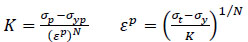
Based on the Elastic-Plastic Deformation (strain hardening) model shown in Fig. (4b). There are several models which can predict theoretical behaviour, such as Ramberg-Osgood, Ludwik, Swift, Hollomon and so on [67]. When using the Ramberg-Osgood model for the plastic behaviour of the pipe, the stress-strain relationship is generally given as:
 |
(23) |
Where K and N are the material behaviour parameters that characterize the plastic behaviour of the material.
 |
(24) |
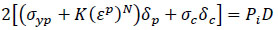
Substituting for σp from Eq. (23 to 20) gives:
 |
(25) |
Eq. (25) can be rearranged, and the composite repair thickness is given as:
 |
(26) |
As can be seen in Eq. (26), it takes into account the plastic deformation but without considering the infill materials and defect geometries. Accordingly, it needs to be improved for a more accurate composite repair thickness calculation.
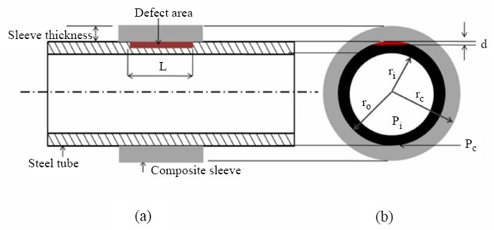
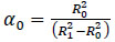
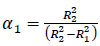
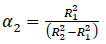
There is another method to analyse the composite thickness as shown in Fig. (5), which considers the interface pressure between the consecutive layers due to the internal pressure. The pipe consists of two bonded layers under internal pressure. There is an inner radius ri and outer radius ro for the pipe and an internal radius ro and external radius re for the composite sleeve, as shown in Fig. (5). Therefore, the surface pressure between the inner layer and the outer layer would be obtained according to the compatibility of radial displacement [56].
Assuming that the radial displacement of the contact surface is equal for both cylinders and  , Eq. (27) can be rearranged and expressed as Eq. (28 and 29) [38].
 |
(27) |
 |
(28) |
 |
(29) |
If the wall thickness is less than 1/10th of the internal radius of the cylinder, tpipe = (ro-ri) the cylinder is considered as a thin-walled cylinder; otherwise, it is considered as a thick-walled cylinder. Therefore, the two concentric-walled cylinders may be a combination of two thin-walled cylinders, a combination of two thick-walled cylinders, or a combination of a thin-walled and thick-walled cylinder.
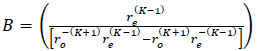
When the two-concentric walled cylinders are a combination of two thin-walled cylinders [73] (Eqs. 30-33):
 |
(30) |
 |
(31) |
When the two concentric-walled cylinders are a combination of thin-walled and thick-walled cylinders:
 |
(32) |
 |
(33) |
Where  ,
,
 and
and
 .
.
However, the cylinder with a combination of two thick-walled cylinders has not been studied further. Therefore, the theory of a combination of two thick-walled cylinders needs to be further studied.
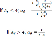
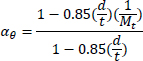
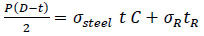
Metal wall loss because of corrosion in a pipe is accounted for in the analysis by considering the remaining strength factor. The factor αθ is a parameter that is affected by the defect shape, size, and pipe geometry, obtained from different criteria [56, 71], which are shown in Table 1. Moreover, Dudhe et al. compared the failure pressure based on the different damaged factors (αθ). There was a significant difference between the theoretical and experimental results. Almost all the criteria were conservative. Although each criterion has a different accuracy level, they all can be expressed as follows (Eqs. 34, 35):
 |
(34) |
 |
(35) |
According to a different criterion, the prediction of the failure pressure can be written as:
 |
(36) |
Eq. (36) is a simple analytical expression that is widely used to predict the failure pressure of corroded pipes reinforced with composite sleeves or wrap. In turn, composite repair thickness (re-ro) can also be determined based on the design pressure according to different criteria.
Overall, these theories and studies highlight the effects of defects on the composite repaired pipelines. However, the existing closed-form solutions do not take into consideration the infill materials and defect sizes. Hence, there is still a lot of room for improvement in the composite repair pipeline analysis.
3.3. Three-layer Model
Initially, Farshad attempted to present a new method taking into consideration the effect of wall thickness and interface pressure between different types of materials for the long-term behaviour of fibre-reinforced pipes. Then, the theory of three-layer thick-walled composite tubes was proposed to find the interface pressure between the layers under the internal pressure [74].
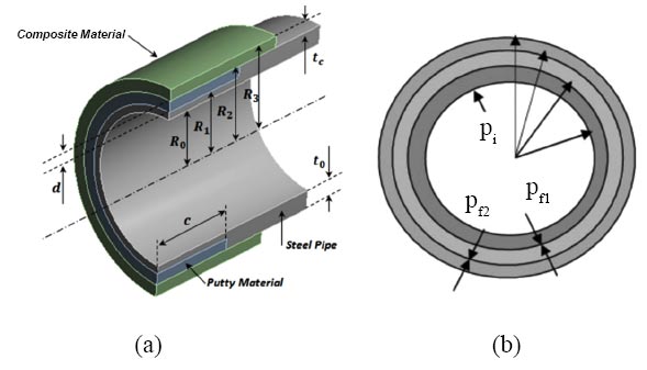
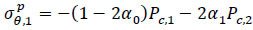
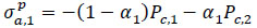
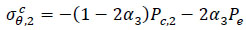
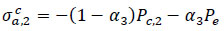
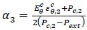
After that, in order to include the effect of the infill material on the calculation of the composite repair thickness, the concept of the three-layer cylinder is introduced, as shown in Fig. (6). Djahida et al. proposed a new methodology where the behaviour of the putty material layer between the steel pipe and composite sleeve was taken into account. This new methodology takes into consideration the effects of wall thickness, contact pressure, and difference of material type. Based on Lame’s relationships, the stress components of each side of the cylinder can be obtained [75] (Eqs. 37-55).
For the outer side of the steel pipe:
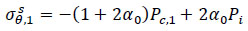 |
(37) |
 |
(38) |
 |
(39) |
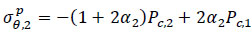
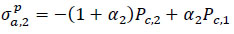
For the inner side of the infill material:
 |
(40) |
 |
(41) |
 |
(42) |
For the outer side of the infill material:
 |
(43) |
 |
(44) |
 |
(45) |
For the inner side of the composite material:
 |
(46) |
 |
(47) |
 |
(48) |
According to the displacement compatibility relationship, the contact pressure Pc,1 between the inner layer and the middle layer, and the contact pressure Pc,2 between the middle layer and the outer layer, both can be solved using:
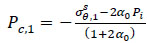 |
(49) |
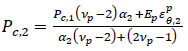 |
(50) |
Where:
 |
(51) |
 |
(52) |
 |
(53) |
 |
(54) |
 |
(55) |
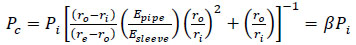
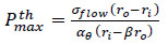
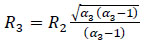
Assuming that R3 = R2 + tc, the composite thickness tc can be calculated by Eq. (56). From the Eq. (56), it can be seen that the composite thickness tc mostly depends on the mechanical properties of the laminate material in the hoop direction. In addition, the repair thickness has a great relationship with the applied internal pressure, which can decide the contact pressure.
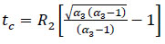 |
(56) |
The internal pressure Pi could be substituted as Pd, which is referred to as the maximum allowable working pressure (MAWP) in order to recover the initial design pressure of the pipeline. Additionally, the internal pressure can also be determined by the yield pressure Pf, aiming to demonstrate the integrity of the composite repair up to the yield of the original pipe [39]. Meanwhile, the steel pipe can reach the ultimate stress, and the composite laminate can reach the ultimate stress/strain. If the internal pressure pi is substituted as the burst pressure Pu, it can restore the load-carrying capacity of the repaired pipeline to an intact pipeline [76]. Therefore, in order to attain different aims, the different internal pressures will decide different composite repair thicknesses.
CONCLUSION
The use of FRP composite materials as repair materials for damaged metallic pipelines is gaining popularity, particularly in the oil and gas industry. The available literature has presented that composite repair systems can be effective in repairing defective pipelines. The current standards and codes are based on certain assumptions that lead to a conservative calculation, such as the composite repair thickness, the failure pressure, the stress distribution of the corroded pipelines and so on. For example, the minimum repair thickness was equal to 4.4 mm as per the ASME PCC-2 standards and 3 mm used in the FEM for the corroded pipeline reinforced with a fiberglass composite repair system [37]. It implies that there is an excessive composite wrap around the corroded pipeline, which leads to an increase in the repair cost.
In order to better understand the effect of defect size on the composite repaired pipelines, many theories have been proposed to explain the stress distribution and predict the failure pressure. Based on previous theoretical foundations, it may potentially derive a more accurate closed-form solution for composite repair thickness, incorporating the effect of infill material and defect sizes (depth, width and length). In this paper, three analytical models are summarized under different assumptions. Generally, based on the thin-walled cylinder theory and the Lame approach, for the two-layer model, there is no direct consideration of the effects of defect sizes or infill materials. On the other hand, for the three-layer model, there is no specific model using the thin-walled composite tube. As a consequence, for proposing a new idea for the multilayer pipes with thin layers, an equation about the minimum composite repair thickness, especially based on the three-layer thin-walled model, can be derived so that it considers not only the corroded layer but also the infill material.
Therefore, the future trend in repairing damaged pipelines is to optimize the design of composite repair systems, such as reducing the usage of composite wrapping layers, using patch repair, proper selection of infill material and heading to a less conservative design philosophy considering the defect geometry, and so on. Furthermore, these are the gaps that need further investigation in advancing these issues.
HIGHLIGHTS
• The minimum repair thickness was reviewed based on different design pressures, which were classified into three cases.
• Three theoretical analysis models, which are the one-layer model, the two-layer model and the three-layer model, are proposed.
• The three-layer model is significant as it can help in the optimization of the minimum repair thickness in the future.
AUTHORS' CONTRIBUTIONS
It is hereby acknowledged that all authors have accepted responsibility for the manuscript's content and consented to its submission. They have meticulously reviewed all results and unanimously approved the final version of the manuscript.
LIST OF ABBREVIATIONS
| FEA | = Finite Element Analysis |
| SMYS | = Specified Minimum Yield Strength |
| MAWP | = Maximum Allowable Working Pressure |
| FEM | = Finite Element Method |
| FRP | = Fiber Reinforced Polymer |
CONSENT FOR PUBLICATION
Not applicable.
FUNDING
This study was funded by Ministry of Higher Education Malaysia, Universiti Malaysia Pahang Al-Sultan Abdullah, Funder ID: MOHE, UMPSA, Awards/Grant number: Grant No.: FRGS/ 1/2018/TK07/UMP/02/8; 2) RDU190150.
CONFLICT OF INTEREST
The authors declare no conflict of interest, financial or otherwise.
ACKNOWLEDGEMENTS
The support provided by the Ministry of Higher Education Malaysia and Universiti Malaysia Pahang Al-Sultan Abdullah for this study is highly appreciated.

