All published articles of this journal are available on ScienceDirect.

Determination of Temperature Stresses during the Construction of Massive Monolithic Foundation Slabs, Taking into Account the Subgrade Compliance
Abstract
Background
The problem of early cracking caused by the heat of concrete hardening is relevant for massive reinforced concrete structures, including foundation slabs. The purpose of this work is to develop the methodology for determining temperature stresses during the construction of foundation slabs, taking into account the interaction with the subgrade.
Methods
The Pasternak elastic foundation model with two-bed coefficients is used for the soil. The temperature of the foundation slab is considered a function of only one coordinate z (temperature changes only along the thickness of the slab). As a result, to determine the stress-strain state of the slab, a fourth-order differential equation for deflection was obtained. A technique for numerically solving the resulting equation using the finite difference method is proposed. The calculation of the stress-strain state is preceded by the calculation of the temperature field, which is performed by the finite element method in a simplified one-dimensional formulation.
Results
The solution to the test problem is presented for a constant modulus of elasticity of concrete over time. The results were compared with finite element calculations in a three-dimensional formulation in the ASNYS software. The calculation was also performed taking into account the dependence of the mechanical characteristics of concrete on its degree of maturity. In this case, the picture of the stress-strain state changes significantly. The proposed method was also successfully tested on experimental data.
Conclusion
The proposed approach can significantly save calculation time compared to the finite element analysis in a three-dimensional setting.
1. INTRODUCTION
The problem of early cracking in hardening massive monolithic reinforced concrete structures has existed almost as long ago as reinforced concrete itself [1]. This problem was first encountered at the beginning of the 20th century when concreting dams [2]. In massive monolithic structures, the technological stress field is formed during the hardening process due to uneven temperature distribution over the cross-section and shrinkage deformations of concrete [3]. Tensile stresses can exceed concrete tensile strength at the stage of structure formation, resulting in early cracking with subsequent development of cracks [4]. This process not only negatively affects the operational properties of the structure, but also can raise the question of the impossibility of its operation in principle [5].
Currently, the volume of high-rise construction is constantly growing, and this problem is relevant not only for hydraulic structures, but also for foundation slabs [6], the thickness of which can reach 2 m or more. Moreover, in most cases, slabs with a thickness of 0.7 m already fall into the category of massive [7].
The massiveness of the structure predetermines the need to develop special technological solutions for regulating the parameters of heat and mass transfer, the rate of concreting, as well as selecting the recipe for concrete mixtures [8]. The selection of effective technological solutions to prevent early cracking can be carried out based on computer modeling methods [9-11].
Currently, the main method for computer modeling of early crack formation processes in hardening massive monolithic structures is the finite element method [12-14].
Existing software products that implement this method (ANSYS, Abaqus, DIANA FEA, Midas Civil, etc.), do not allow taking into account a number of significant factors, including changes in the physical and mechanical characteristics of concrete over time due to concrete strengthening, changes in the thermophysical characteristics of concrete during its hydration, etc [16-19]. In the ANSYS and Abaqus packages, this problem is partially solved by creating custom extensions [20-22], but the possibilities for modifying existing software products are very limited.
Calculation of temperature fields and stresses in hardening massive monolithic structures, as a rule, is performed in a three-dimensional setting [23-25]. This approach requires significant computer time and resources. A simplified method is proposed [26] for determining stresses in massive monolithic foundation slabs during construction, which allows, based on the hypothesis of plane sections, to reduce the three-dimensional problem of determining the stress-strain state to a one-dimensional one. In this case, the subgrade under the foundation slab is assumed to be absolutely rigid. The purpose of this work is to develop a simplified method for calculating the stress-strain state during the construction of massive monolithic foundation slabs, taking into account the subgrade compliance.
2. MATERIALS AND METHODS
In another paper [26], it was shown that, with the exception of the edges, the temperature distribution in massive monolithic foundation slabs during the construction process is one-dimensional. Based on this fact, the modulus of elasticity of concrete, as well as temperature deformations, are assumed as functions of only one coordinate z.
When constructing the model of slab deformation, the hypothesis is used that layers parallel to the middle surface do not press on each other (σz = 0). Also, the proposed model does not take into account the reinforcement of the slab. This is justified by a previous study [27]. In that paper, for the slab on an absolutely rigid base, it was shown that even with a large percentage of reinforcement (µ = 2%), the influence of the reinforcement on the stress-strain state is not so significant. This is also explained by the fact that the coefficients of linear thermal expansion of concrete and steel are very close. In addition to the hypothesis that stresses σz are equal to zero, the hypothesis of the straight normal to the middle surface is used.
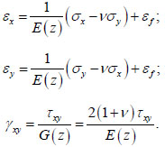
From a physical point of view, concrete deformations can be represented as the sum of elastic and forced deformations:
 |
(1) |
Here 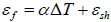 are the forced deformations, representing the sum of temperature deformations and shrinkage deformations.
Stresses are expressed through strains from (1) in the form:
 |
(2) |
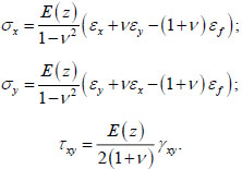
The straight normal hypothesis assumes the linear distribution of deformations across the thickness of the slab:
 |
(3) |
where  are the deformations of the middle surface;
 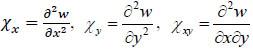 are the changes in slab curvature, w is the deflection.
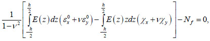
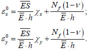
When obtaining the resolving equation, it is assumed that the elastic foundation does not prevent the expansion of the foundation in the direction of the axes x and y, i.e. axial forces 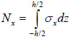 are
are 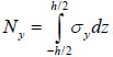 assumed to be zero. Substituting (3) into (2) followed by substituting the stress σx formula into the expression for the axial force Nx leads to the expression:
 |
(4) |
where 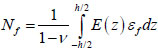 .
.
The following notations are introduced:
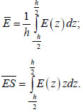 |
(5) |
The first value is the average modulus of elasticity of concrete over the thickness, and the second value is equivalent to the product of the average modulus of elasticity of concrete and the static moment of the cross-section.
Taking into account the accepted notation (5), expression (4) takes the form:
 |
(6) |
Similarly, the condition Ny = 0 leads to the following equality:
 |
(7) |
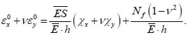
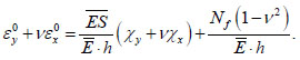
The deformations of the middle surface can be obtained from (6) and (7) in the form:
 |
(8) |
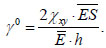
In addition to axial forces Nx and Ny, the shear force  also vanishes, which leads to the expression:
 |
(9) |
The bending moment Mx in the slab will be written as:
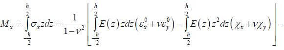 
|
(10) |
where 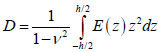 is the cylindrical stiffness of the slab,
 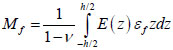 .
.
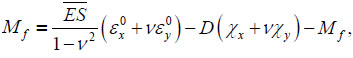
After substituting (8) into (10), the expression for the bending moment Mx takes the form:
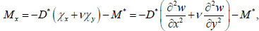 |
(11) |
where 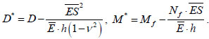 .
.
Likewise for the moment My:
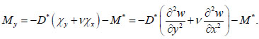 |
(12) |
Torque is defined as follows:
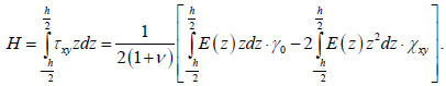 |
(13) |
Taking into account (9), the expression for torque takes the form:
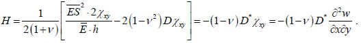 |
(14) |
The differential equation for the equilibrium of the slab on the elastic foundation has the form:
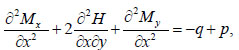 |
(15) |
where q is the surface load and p is the reactive soil pressure.
In the problem of determining temperature stresses, the value q is taken equal to zero. The Pasternak model with two bed coefficients C1 and C2 [27], in which the differential equation of the sedimentary surface is as follows:
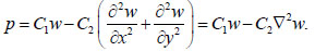 |
(16) |
Bed coefficients C1 and C2 in the Pasternak model in the case of a homogeneous soil mass are determined according to another study [28]:
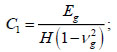 |
(17) |
 |
(18) |
where H is the thickness of the soil mass, Eg is the modulus of elasticity of the soil, and vg is the Poisson’s ratio of the soil.
Substituting (11, 12, 14, 16) into the equilibrium Eq. (15) leads to the main resolving equation:
 |
(19) |
Since it is assumed that temperature deformations depend only on z, the value ∇2M* becomes zero.
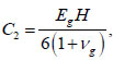
Moments M* are taken into account only in boundary conditions. For an edge perpendicular to the axis x, the bending moment Mx and reduced shear force  must be equal to zero:
 |
(20) |
Similarly, for an edge perpendicular to the y axis:
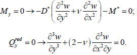 |
(21) |
The solution of Eq. (19) is performed numerically by the finite difference method. For the rectangular slab with the dimensions a×b, a quarter is considered due to its symmetry. Two rows of contour points are introduced on the edges x = a/2 and y = b/2 (Fig. 1). Finite-difference analogue of the Eq. (19) in the k-th node has the form:
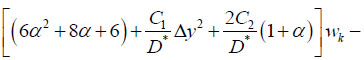 
|
(22) |
where α = ∆y2 / ∆x2
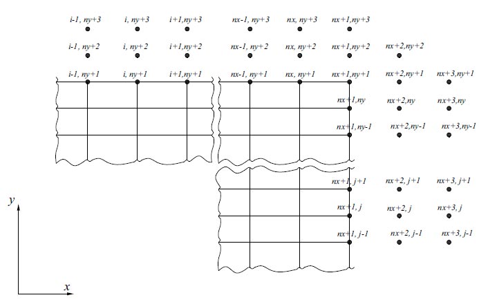
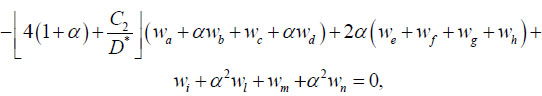
Layout of contour points.
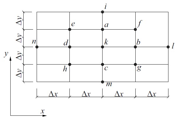
Layout of nodes for formula (22).
The layout of the nodes for formula (22) is shown in Fig. (2).
Eq. (22) is compiled for all mesh nodes at i = 1...nx+1 and j = 1...ny+1, where nx and ny are, respectively, the number of segments along x and y.
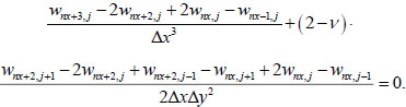
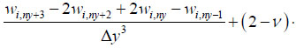
The first condition in (20) is approximated as follows:
 |
(23) |
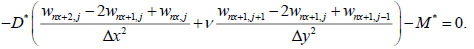
The approximation of the second condition in (20) has the form:
 |
(24) |
Eqs. (23-24) are compiled at j = 1… ny +1.
Conditions (21) are approximated similarly:
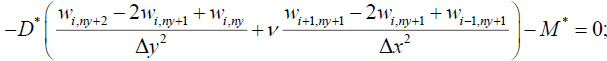  
|
(25) |
Eq. (25) are compiled for i = 1… nx +1.
As a result, the total number of equations will be:
 |
(26) |
which is one less than the number of unknowns (the deflection at point nx+2, ny+2 remains uncertain)
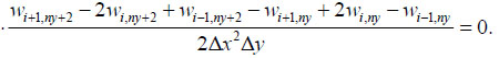
As an additional condition, it is proposed that the sum of the bending moment Mx on the continuation of the line x=a/2 at the point (nx + 1, ny + 2) and bending moment My on the continuation of the line y=b/2 at point (nx + 2, ny + 1) is equal to zero:
|
(27) |
Thus, finally, at each time step, the problem of determining the stress-strain state is reduced to 3×nx+3×ny+nx×ny+6 linear algebraic equations with the same number of unknowns.
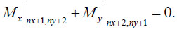
The calculation of temperature stresses is preceded by the determination of the temperature field, which is found in the one-dimensional equation [29]:
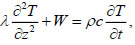 |
(28) |
where λ is the thermal conductivity coefficient, T is the temperature,  is the power of internal heat generation sources (W/m3), ρ is the density of the material, c is the specific heat capacity of the material, and t is the time.
The temperature field is determined using the finite element method by solving the system of equations:
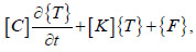 |
(29) |
where [C] is the damping matrix, [K] is the thermal conductivity matrix, {T} is the vector of temperature values at the nodes and {F} is the load vector.
The dependence of the strength and deformation characteristics of concrete on the time and hardening temperature is taken into account when calculating the stress-strain state.
The compressive strength of concrete is considered as the function of its degree of maturity:
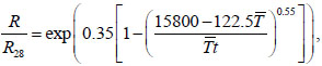 |
(30) |
where R28 is the compressive strength of concrete at the age of 28 days,  , t is the age of concrete in hours, DM is the degree of maturity of concrete, determined by the integral:
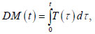 |
(31) |
where T(τ) is the concrete temperature at time τ.
The modulus of elasticity of concrete is taken as a function of its compressive strength:
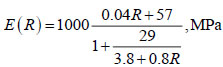 |
(32) |
3. RESULTS AND DISCUSSION
The first step to verify the developed methodology was to solve the test problem with a constant modulus of elasticity of concrete E = 3⋅104 MPa over time. Verification was carried out by comparison with calculations in the ANSYS software package in a three-dimensional setting.
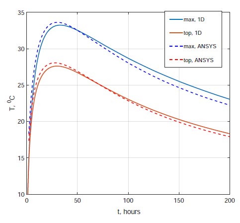
Change in time of the maximum temperature in the foundation, as well as the temperature on the upper surface.
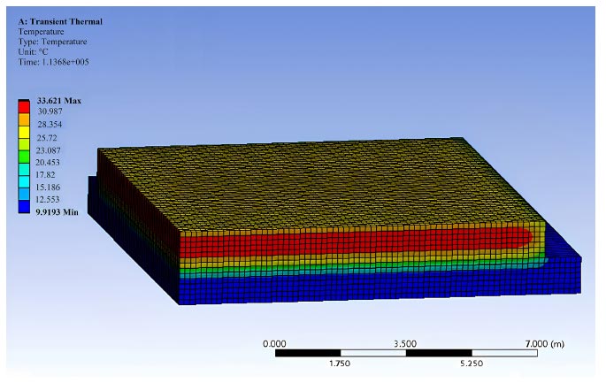
Temperature distribution at time t=32 h.
The concrete heat release function was adopted based on data from [30]:
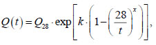 |
(33) |
where t is the time in days, Q28 is the amount of heat released during the first 28 days of hardening, MJ/m 3, coefficients k and x depend on the rate of concrete hardening.
The calculation was performed for B25 class concrete according to Russian standard GOST 26633-2012 at Q28=130MJ/m3, k=0.13, x=0.42. The thermophysical characteristics of concrete were assumed to be constant over time: λ=2.67 W/(mx°C) c=1000J/(kgx°C), ρ=2500 kg/m3. The coefficient of linear thermal expansion of concrete was α=10-5 l/°C. The Poisson's ratio of concrete was also assumed to be constant and equal to v=0.2. The foundation slab thickness was h = 1 m, dimensions in the plan were 20 x 20 m. The thickness of the soil mass was taken equal to H = 1 m. Thermophysical characteristics of the soil: ρg= 1600 kg/m3, cg= 1875 kg/m3, λg= 1.5 W/(mx°C). Deformation characteristics of soil: Eg= 10MPa, vg= 0.3. Heat transfer coefficient on the upper surface of the foundation slab ht= 4 W/(m2x°C), ambient temperature, concrete mixture and initial soil temperature T 0= 10°C.
Fig. (3) shows graphs of the maximum temperature changes in the foundation slab, as well as the temperature on the upper surface, obtained using the author’s method in a one-dimensional setting and ANSYS in a three-dimensional setting. The discrepancy between the results is insignificant. The temperature distribution obtained in ANSYS at time t= 32 h is shown in Fig. (4).
Fig. (5) shows graphs of changes in stress σx over time at the lowest point in the center of the foundation slab. The maximum stresses calculated using the author's method and using three-dimensional modeling in ANSYS are practically the same. When calculated by the author's method, σx,max= 2.745 MPa, and when calculated in ANSYS: σx,max= 2.739 MPa.
The pictures of the deformations of the foundation slab obtained using the author’s method and in ANSYS also coincide (Figs. 6 and 7).
ANSYS software package does not have the ability to take into account the dependence of the elastic modulus of concrete on time. When this factor is taken into account, the picture of the stress-strain state changes dramatically. Fig. (8) shows graphs of stress σx changes in the center of the foundation slab at the bottom point, in the middle of the thickness, and also at the top point. The dashed lines correspond to the solution at a constant elastic modulus, the solid lines correspond to the solution taking into account the dependence of the elastic modulus of concrete on the degree of its maturity. Taking into account the time-varying elastic modulus leads to a noticeable reduction in stress.
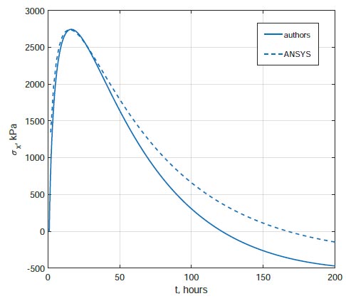
Change of stresses in time at the lowest point in the center of the foundation slab.
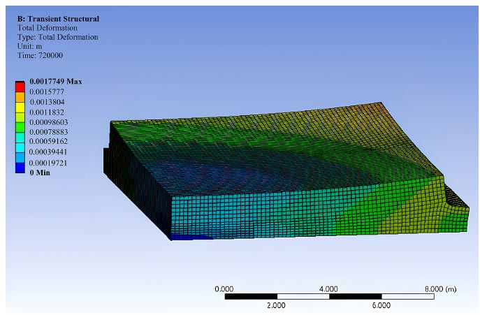
Distribution of displacements of the foundation slab at t = 200 h, obtained in ANSYS.
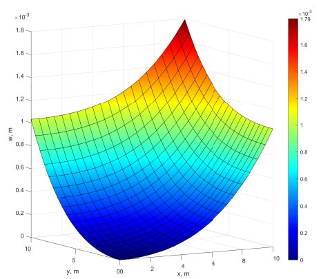
Distribution of displacements of the foundation slab at t = 200 h, obtained by the author’s method in MATLAB.
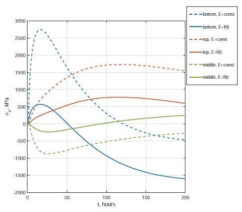
Change in time of stresses σx along the center of the foundation slab.
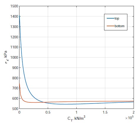
Dependence of maximum tensile stresses in the center of the slab on the bed coefficient C1.
It is also of interest to study the influence of subgrade rigidity on the magnitude of temperature stresses in the foundation slab. To analyze this factor, the calculations were performed for various values of the bed coefficient C1 from 0 to 2 ∙ 10 5 kN/m3. The ratio C1/C2 remained constant and equal to 8.57 m-2.
Fig. (9) shows graphs of the dependence of the maximum stress σx in the center of the slab at the top and bottom points on the bed coefficient C1. The stresses at the bottom point decrease with an increase in the bed coefficient C1 from 0 to 2.6∙104 kN/m3 . The minimum is 560 kPa. Then, after passing the minimum point, stresses increase slightly and asymptotically tend to a value of approximately 573 kPa.
The stresses at the top point decrease with an increase in the bed coefficient C1 from 0 to 8∙10 4 kN/m3. The minimum is 543 kPa. Then, after passing the minimum point, stresses increase slightly and asymptotically tend to a value of approximately 588 kPa. The difference in stress values on the upper and lower surfaces can be explained by different heat transfers at the “air-foundation slab” and “foundation slab - subgrade” boundaries.
At C1≥4.104 kN /m3, with an error of no more than 5%, the base can be considered absolutely rigid and calculations can be carried out using simplified methods [26, 30].
In addition to the influence of the bed coefficient C1 on stresses, a study was also carried out on the influence of the coefficient C2 at a constant C1. Fig. (10) shows the dependence of the maximum tensile stresses in the center of the slab on the coefficient C2 at C1 = 104 kN/m3 = const. The stresses increase with increasing coefficient C2. The ratio of the coefficients C2 and C1 for homogeneous subgrade is equal to H2(1-vg)/6. Therefore, the stresses in the foundation will increase with increasing thickness of the compressible subgrade layer. As Poisson's ratio of subgrade increases, the stresses in the foundation will, on the contrary, decrease.
To confirm the reliability of the results, the developed methodology was also tested on the experimental data presented in a previous study [31]. The work presents the results of temperature and stress measurements in a foundation slab with dimensions of 13.25×20.75 m and a thickness of 2 m. That work also presents the results of finite element modeling of temperature fields and stresses in a three-dimensional formulation. Finite element analysis was carried out taking into account the soil mass, the thickness of which was assumed to be 10 m [31]. Soil elastic modulus was Eg= 3.104 kPa, Poisson's ratio vg= 0.2. The slab concrete at the age of 28 days had a compressive strength R28= 34.2 MPa and an elastic modulus of 34.4 GPa. The cement grade was CEM III/A 32.5 N with a content of 240 kg/m 3 in 1 m3 of concrete mixture. The initial temperature of concrete mixture was T 0= 24 ° C, soil temperature was Tg= 16° C, concrete density ρ= 2349 kg/m 3, soil density ρg= 2070 kg/m 3, concrete thermal conductivity coefficient λ= 2.67 W/(m∙°C), soil thermal conductivity coefficient λg= 1.4 W/(m∙°C), specific heat capacity of concrete c= 1000 J/(kg∙°C), specific heat capacity of the soil cg J/(kg ∙°C), heat transfer coefficient on the upper surface ht= 30 W/(m2x°C).
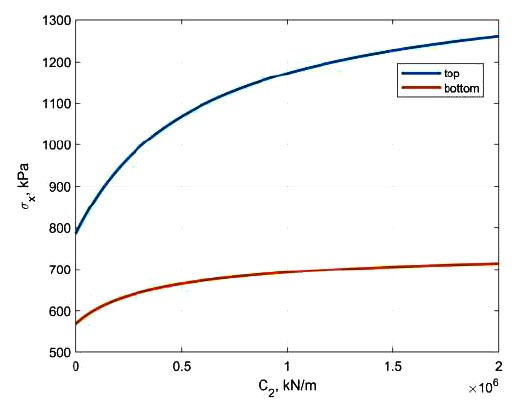
Dependence of maximum tensile stresses in the center of the slab on the bed coefficient C2.
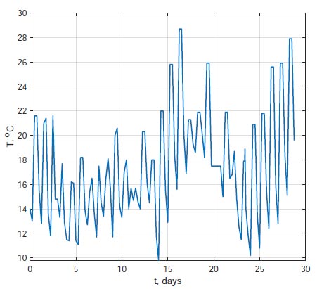
Graph of changes in ambient temperature over time.
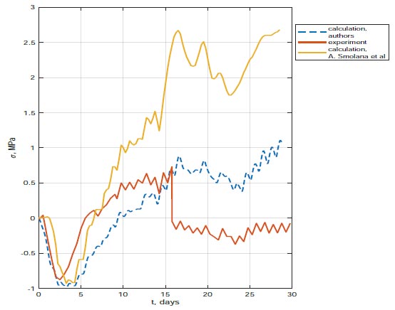
Comparison of calculation results using the author’s method with experimental data and calculation using the method. Available online under the terms of the Creative Commons Attribution License (http://creativecommons.org/licenses/by/4.0) [31].
The ambient temperature was taken in accordance with the results of field measurements. A graph of changes in ambient temperature over time is shown in Fig. (11).
The heat release function was taken in accordance with expression (33) at k =0.135, x =0.61, Q28 =83 MJ/ m3.
Fig. (12) shows a graph of changes in normal stresses in the center of the slab. The red line corresponds to experimental data, the yellow line is the result of finite element modeling presented in [31], and the blue dashed line is the result of calculations using the author’s method. Fig. (12) shows that the calculation results using our method are in better agreement with the experimental data. At the time of t= 16 days, a jump to almost zero is observed in the experimental curve, which is probably associated with the failure of the sensor or the formation of a crack.
CONCLUSION
1. A simplified model for determining temperature stresses during the construction of massive monolithic foundation slabs, taking into account the subgrade compliance, is proposed. The problem of calculating temperature stresses is reduced to a fourth-order differential equation regarding the deflection of the slab. A technique for its numerical solution by the finite difference method is proposed.
2. The proposed methodology was tested by comparison with the results of calculations in the ANSYS software package in a three-dimensional setting without taking into account the dependence of the elastic modulus of concrete on time. The discrepancy between the maximum stresses and displacements according to the author’s method and in ANSYS is insignificant.
3. It is shown that when taking into account the dependence of the elastic modulus of concrete on time, which cannot be done with standard tools of the ANSYS software package, the picture of the stress-strain state changes dramatically.
4. A study was carried out on the influence of subgrade rigidity on temperature stresses in the slab. It has been established that with increasing rigidity of the subgrade, the stresses in the foundation slab first decrease, and then, after passing the minimum point, they increase slightly and asymptotically tend to the final value. The range of change in the subgrade bed C1 coefficient has been determined, in which the compliance of the subgrade can be neglected and it can be considered absolutely rigid. In addition to the influence of the bed coefficient C1 on stresses, a study was also carried out on the influence of the coefficient C2. As the ratio of C2 to C1 increases, the stresses increase.
5. The reliability of the developed methodology is confirmed by comparison with the experimental results. The proposed method is much less expensive in terms of computer time than finite element analysis in a three-dimensional formulation. This allows the proposed method to be used for quickly assessing the risk of early cracking during concreting of monolithic foundation slabs.
6. Currently, the experimental database on temperature stresses during the construction of massive monolithic foundation slabs is extremely scarce. The prospect of our further research is to expand the experimental base and test the developed theoretical model on our own experimental data.
AUTHORS' CONTRIBUTIONS
It is hereby acknowledged that all authors have accepted responsibility for the manuscript's content and consented to itssubmission. They have meticulously reviewed all results and unanimously approved the final version of the manuscript.

