All published articles of this journal are available on ScienceDirect.

Experimental and FE Numerical Analysis Of RC Shear Walls Retrofitted Using CFRP and Steel Plates
Abstract
Introduction
Shear walls are recognized to be one of the main structural systems that resist lateral loads such as wind and earthquakes. This paper presents some advanced experimental and finite element FE analyses performed on five shear wall samples; four specimens were retrofitted using two different techniques.
Methods
The experimental program presents five specimens retrofitted using both CFRP and an external steel plate. The debonding of CFRP was the dominant mode of failure for the first two tested shear walls retrofitted with CFRP, so adding an external steel plate was an available solution that was conducted to increase the load capacity of the remaining specimens. A 3D finite element FE model was created using the commercial software Abaqus. This paper introduces a new and original hybrid strengthening of the shear walls (using CFRP and steel plates), which has not been studied before in the literature, and also shows some advanced features to simulate the CFRP attachment to the concrete layer to capture both the load capacity and the debonding failure, which was observed in the experimental results.
Results
The FE results were in good agreement with the experimental results for all tested specimens.
Conclusion
The retrofitted shear walls using CFRP and steel plate recovered almost 38% of the shear capacity of the control specimen.
1. INTRODUCTION
Shear walls provide an efficient lateral force resisting system.. It provides large stiffness to the structure, so it will be stable when subjected to lateral loadings such as an earthquake. Shear walls can effectively reduce the maximum displacement values and story-drift values of the structure [ 1]. Ductility is considered one of the important areas of study related to shear wall design and retrofitting of reinforced concrete RC structure. Several factors govern shear wall ductility: the shear wall geometry, the applied loads, and the steel reinforcement [ 2-4]. Many researchers performed several studies to reduce the seismic damage to RC structures [ 5-8]. Some of these studies were based on finite element FE numerical modeling. The non-linear static (pushover) analysis method is considered to be the most widely used technique for the seismic assessment of Reinforced Concrete (RC) structures [ 9-11].
There is a growing demand within the engineering community to preserve and retrofit existing RC buildings, especially the deteriorated ones and those that lie in active seismic zones [ 12]. Recently, strengthening RC structures with FRP materials has become one of the most widely used techniques. This is due to their high tensile strength, low weight, ease of application, durability, stiffness, excellent damping behavior, flexural strength, and, most importantly, superior corrosion resistance [ 13].
Layssi et al. [ 14] conducted tests on RC shear wall specimens under cyclic loading to examine the seismic response of poorly detailed shear walls, initially introduced by Taghdi et al. [ 15]. The study proposed a carbon fiber-reinforced polymer CFRP jacket to be applied for flexural strengthening and CFRP strips for shear strengthening. The CFRP technique improved the dis- placement ductility, and energy dissipation and prevented premature failure of the lap splices. El-Sokkary and Galal [ 16] found that the flexural and shear capacities of CFRP-retrofitted shear walls were significantly higher than those of the control shear wall.
The failure modes of RC shear walls include shear failure, flexural failure, and flexural-shear failure, the latter being characterized by a combination of shear and flexural responses. Sometimes, several non-conventional modes of failure are observed for structural elements retrofitted using composite materials like CFRP. This premature failure varies from the rupture of the CFRP material itself to the debonding failure of the adhesive concrete layer [ 17]. Almassri and Halahla [ 18] used an innovative retrofitting technique that used both CFRP and external steel plate. Such a hybrid technique was employed to retrofit deteriorated RC beams that failed by the separation of the concrete cover due to the large stresses developed in the concrete cover area. This retrofitting combination prevented the premature mode of failure and increased the load capacity of the corroded RC beam.
The FEM-based computer software Abaqus has been used several times to simulate RC shear walls [ 19-21]. Kong et al. [ 22] proposed a 3D finite-element model using the program Abaqus to simulate shear walls wrapped with GFRP (glass FRP). In this model, the GFRP was modeled using a SHELL element, and there was a good agreement between the results of the FE model and the test. Sakr et al. [ 23] compared the outcomes of their FE model for CFRP strengthened shear walls with experimental findings from existing literature. It was found that the FE model developed in Abaqus managed to predict the failure mode of the CFRP debonding.
This paper employs the Concrete Damage Plasticity (CDP) model to replicate the behavior of concrete under both compression and tension damage conditions. According to the CDP model, the primary failure mechanisms of concrete are considered to be tensile cracking and compressive crushing. In this framework, the behavior of uniaxial tension and compression is described using damaged plasticity. The CDP model is an adaptation of the Drucker-Prager strength theory. Many previous studies used the CDP model to forecast the performance of shear walls and FRP strengthened shear walls [ 24-28]. The nonlinear 3D FE numerical model presented here, utilizing Abaqus, offers the engineering community a compu- tational resource for designing CFRP retrofitted RC shear wall structures. This research's significance lies in introducing an innovative hybrid retrofitting approach employing both CFRP and external steel plates. There are no available studies focused on hybrid retrofitting techniques that combine different materials. Through FE modeling, the failure and crack pattern, load capacity, and ductility improvement due to the retrofitting technique will be predicted. Therefore, with this proposed FE numerical modeling, the door will be opened shortly so that the engineers can find an optimum strengthening strategy to ensure both ultimate load capacity and ductility for RC shear wall design.
2. MATERIALS AND METHOD
2.1. Specimens for Testing and Retrofitting Configurations
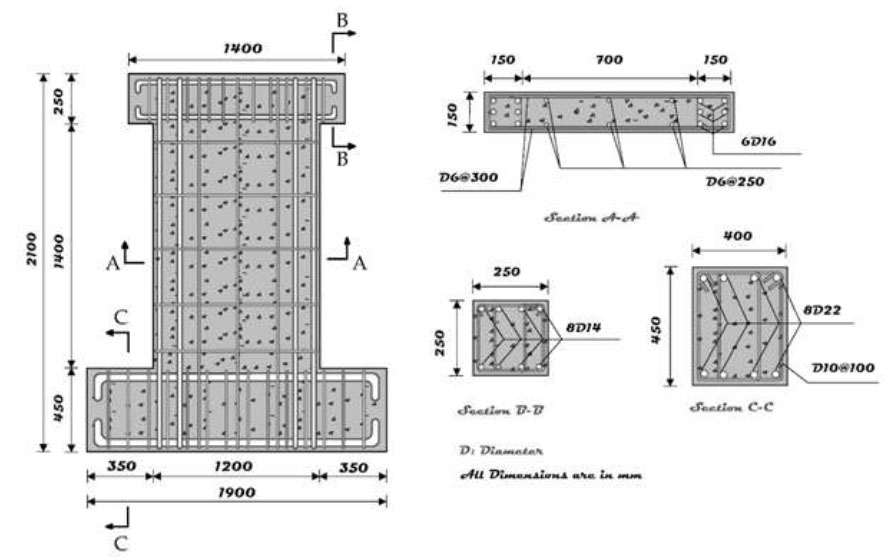
Five shear wall specimens represent poor shear-designed concrete walls. The test specimens consist of half-scaled RC wall specimens. They were fabricated and subjected to testing in the laboratory to examine the impact of shear retrofitting using four distinct CFRP configurations. Among these configurations, two of the retrofitted specimens were reinforced with both CFRP and external steel plates. Fig. ( 1) provides the dimensions and reinforcement specifications of the test specimens.
All shear wall specimens share identical geometric dimensions and reinforcement layouts. They comprise three structural components: the upper beam for transmitting horizontal loads to the wall, the main body simulating a shear wall, and the base for securing the specimen to the floor. The upper beam features a cross-section measuring 250×250 mm. For longitudinal reinforcement, eight deformed bars with a diameter of 14 mm wereutilized in the upper beam. Additionally, deformed bars with a diameter of 10 mm, spaced at intervals of 100 mm, served as stirrups within the upper beam. The base beam wascharacterized by a cross-section measuring 400×450 mm. It employed 22 mm diameter deformed bars as longitudinal reinforcement. Stirrups in the base footing consisted of deformed bars with a diameter of 10 mm, spaced at intervals of 100 mm. The dimensions of the wall wereas follows: length (l) = 1000 mm, height (h) = 1400 mm, and thickness (t) = 150 mm. The ratio of the wall's height to its length (h/l) is 1.4. To replicate the deficient details found in existing RC structures, boundary members at the sides of the walls were not considered.
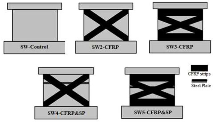
The characteristics of the specimens are outlined in Table 1. SW-Control 1 served as the benchmark specimen, undergoing testing without any retrofitting measures. On the other hand, four of the specimens (SW2-CFRP, SW3-CFRP, SW4-CFRP&SP, and SW5-CFRP&SP) were tested after retrofitting using two different retrofitting strategies (CFRP and steel plate), adding steel plates were adopted after observing the premature mode of failure of the retrofitted specimens by the CFRP debonding. CFRP strips were symmetrically attached to the two sides of the concrete wall. Fig. ( 2) provides an elaborate depiction of the retrofitting configurations involving CFRP and epoxy-coated steel plates. Lateral strips, 200 mm in width, were employed for retrofitting along both diagonal axes of the shear walls.
Reinforcement specifications of test specimens (dimensions in mm).
Retrofitting of five specimens.
| Specimen No. |
Fc' (MPa) Concrete Compressive Strength |
Aspect Ratio l/h |
Diameter/spacing (mm) Horizontal Reinf. |
ρH
Horizontal Reinforcement Ratio |
Diameter/spacing (mm) Vertical Reinf. |
ρV
Vertical Reinforcement Ratio |
|---|---|---|---|---|---|---|
| SW-Control | 24 | 1.4 | D6/300 | 0.002 | D6/250 | 0.0183 |
| SW2-CFRP | ||||||
| SW3-CFRP | ||||||
| SW4-CFRP&SP | ||||||
| SW5-CFRP&SP |
Fig. ( 2) shows the first control specimen, which was left without retrofitting. The second and third were retrofitted using CFRP only (the width of the strip is proposed 200mm), with two configurations (one with diagonal only and the other with two horizontal and diagonal). After the second and third specimens were tested, the fourth and fifth specimens were proposed, which include steel plates (150mm width) bonded to the shear wall face with an expansion anchorage diameter of 15 mm (as shown in Fig. 3) to ensure full anchorage with the existed CFRP. Properties of steel reinforcement bars, steel plates, and CFRP are described in the following Tables 2, 3, and 4.
2.2. Properties of Used Materials
2.2.1. Steel Reinforcement and Steel Plates
The reinforcing bars (steel) were made of natural S300 plain rods for 6mm bars and S400 halfhard steels; standard ribbed reinforcing steel bars were utilized for diameters ranging from 10 to 22 mm. The properties of the steel bars were measured, and the results are presented in Table 2. The properties of steel plates used in retrofitting SW4-CFRP&SP and SW5-CFRP&SP are shown in Table 3.
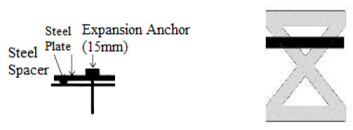
a. Anchorage of steel plates b. Schematic of hybrid retrofitting.
| Reinforcement Diameter (mm) | Yield Strength F y (MPa) | Ultimate Strength F u (MPa) | Bar Type |
|---|---|---|---|
| 6 | 331 | 422 | Plain |
| 10 | 420 | 513 | Deformed |
| 14 | 423 | 530 | Deformed |
| 16 | 428 | 533 | Deformed |
| 22 | 425 | 515 | Deformed |
| Thickness (mm) | Retrofitted Specimen | Yield Strength F y (MPa) | Ultimate Strength F u (MPa) | Elongation % | Poisson's ratio |
|---|---|---|---|---|---|
| 1 | SW4-CFRP&SP | 292.1 | 357.2 | 15 | 0.3 |
| 1.5 | SW5-CFRP&SP | 292.4 | 363.5 | 15 | 0.3 |
| Typical Fibre Properties (nominal values) | |||
|---|---|---|---|
| Fibre Thickness (mm) | Tensile Strength (MPa) | Tensile Modulus (MPa) | Elongation % |
| 0.2930 | 4000 | 240,000 | 1.50 |
| Cured Laminate Properties (design values) | |||
| Fibre Thickness (mm) | Tensile Strength (MPa) | Tensile Modulus (MPa) | Elongation % |
| 0.1200 | 3200 | 220,000 | 1.35 |
| Parameter | Value |
|---|---|
| Dilation angle (ψ) | 34° |
| Eccentricity (e) | 0.1 |
| f b0 /f c0 (which is the ratio of the initial equibiaxial compressive yield stress to the initial uniaxial compressive yield stress) | 1.16 |
| K (ratio of second stress invariant in the tensile meridian) | 0.667 |
| μ (viscosity parameter) | 0.0001 |
2.2.2. CFRP Laminates and Epoxy Resin
The Sikadur 330 epoxy resin was employed to bond the CFRP strips to the concrete face. According to the manufacturer, the tensile strength of the resin is 30 MPa, while the elastic modulus is 3800 MPa. Sikawrap 530-C uniaxial (fiber orientation =0 degrees) were used as CFRP strips; properties of the CFRP strips are presented in Table 4 for both nominal and design values.
3. FE NUMERICAL MODELLING
3.1. Materials Constitutive Models
Finite element analysis commercial software (Abaqus/standard) was employed here in this paper to model the control specimen first and then the retrofitted RC shear walls. The concrete behavior was simulated using the Concrete Damage Plasticity (CDP) model [ 29]. The CDP parameters are presented in Table 5.
Concrete parameters CDP model.
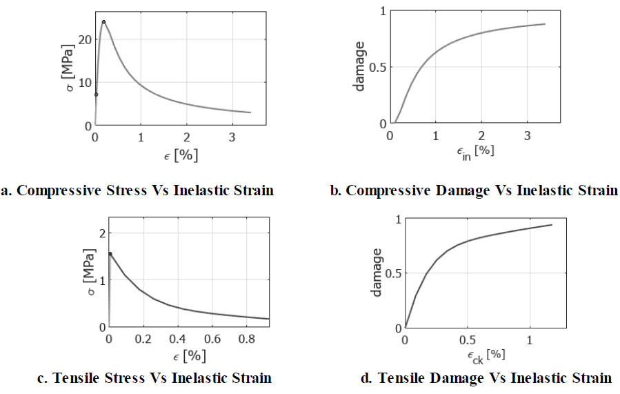
Both concrete compression and tension damage parameters were calculated based on concrete Young's modulus and compressive strength Fc', and the ACI 318 code equation was used
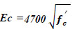 ), where fc': 24 MPa and Fct= 1.65 MPa for all specimens. The compression behavior and tension behavior of concrete are presented in Fig. (
4a-d).
), where fc': 24 MPa and Fct= 1.65 MPa for all specimens. The compression behavior and tension behavior of concrete are presented in Fig. (
4a-d).
An elastoplastic behavior was assumed for both steel reinforcement bars and steel plates; the modulus of elasticity 200 GPa was used, and the yield and ultimate strength values shown in Tables 2 and 3 were used to generate the full elastoplastic behavior, which was adopted in this FE model as presented in Fig. ( 5).
The CFRP strips were implemented in the FE model as lamina-type elastic behavior, and the Hashin damage model was proposed as a damage model for the FRP composites. Tables 6 and 7 present the CFRP constitutive model used in Abaqus.
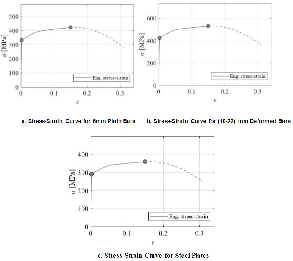
FE constitutive models for steel material.
| Young’s Modulus, E11 | 220 GPa |
|---|---|
| Young’s modulus, E22 | 17 GPa |
| Poisson’s ratio, n12 | 0.32 |
| Young’s modulus,G12 | 4.5 GPa |
| Young’s modulus,G13 | 4.5 GPa |
| Young’s modulus,G23 | 2.5 GPa |
a. FRP composites damage model.
| Longitudinal Tensile Strength | Longitudinal Compressive Strength | Transverse Tensile Strength | Transverse Compressive Strength | Longitudinal Shear
Strength |
Transverse Shear
Strength |
|---|---|---|---|---|---|
| 3200 MPa | 2400 MPa | 111 MPa | 290 MPa | 137 MPa | 137 MPa |
| Longitudinal Tensile Fracture Energy Gf | Longitudinal Compressive Fracture Energy Gf | Transverse Tensile Fracture Energy Gf | Transverse Compressive Fracture Energy Gf |
|---|---|---|---|
| 100 | 100 | 0.2 | 0.2 |
| Viscosity coefficient for Longitudinal Tensile direction | Viscosity coefficient for Longitudinal Compressive direction | Viscosity coefficient for Transverse Tensile
direction |
Viscosity coefficient for Transverse Compressive
direction |
|---|---|---|---|
| 0.0005 | 0.0005 | 0.0001 | 0.0001 |
3.2. FE Numerical Model Tools
In this paper, RC shear walls were modeled using a dynamic explicit solver, the total displacement of 20 mm was applied in 10 seconds, and the loading rate was 2 mm/s (the slow dynamic loading rate expresses a static procedure). The FE model included a 3D solid element with 8-node (C3D8R), which was utilized for concrete. The shell element (S4R) for both CFRP sheets and steel plates, as well as the steel bars, were modeled as linear elements with 2-nodes and 2-D trusses (T2D2). Steel reinforcement bars were considered to be incorporated in the RC shear wall region, and tie contact was employed to create the connection between steel plates and shear walls as no debonding was observed in the outcomes of the experiment. To capture the debonding mode of failure of the CFRP strips that occurred in the experiment, the connection point between the CFRP strips and the surface of the RC shear wall was simulated using cohesive behavior. The traction separation law (shown in Fig. 6) was implemented in the model. The stiffness factors values and damage initiation stresses used in this study are presented in the following Table 8. The shear wall specimens were fixed to the floor, and a displacement control was implemented to the upper part of the head beam; lateral supports were applied in opposite directions, as shown in Fig. ( 7).
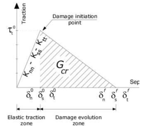
Traction-separation law, (abaqus/standard) [ 30].
| Normal Stress σ n0 (MPa) | Shear Stress 1; τ ss (MPa) | Shear Stress 2; τ tt (MPa) |
|---|---|---|
| 1.65 | 1.35 | 1.35 |
| Normal stiffness K nn (N/mm 3) | Shear stiffness K ss (N/mm 3) | Shear stiffness K tt (N/mm 3) |
| 30 | 3.5 | 3.5 |
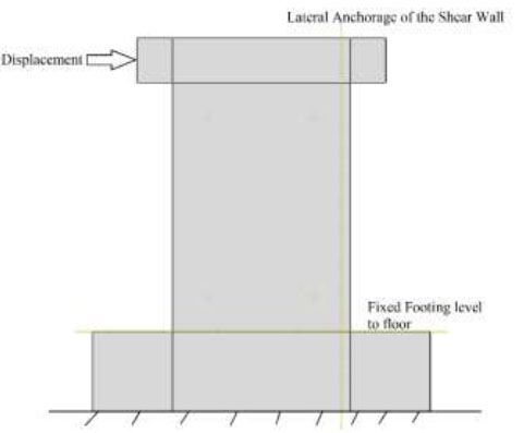
Test set-up (boundary conditions).
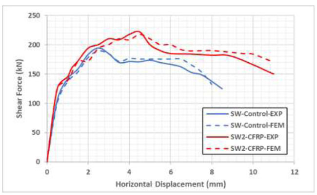
Load deflection curves for SW control and SW2-CFRP.
4. RESULTS AND DISCUSSION
4.1. Load Deflection Curves
After the shear walls were tested experimentally and using the FE model, the following load-deflection curves were drawn, as presented in Figs. ( 8-11). Fig. ( 8) shows a comparison between the SW control specimen and the first proposed retrofitting strategy (using only diagonal CFRP strips in both faces).The load capacity was increased by 17% (ultimate shear force before retrofitting 189.8 kN and 222 kN after retrofitting). The outcomes of the FE model closely matched the experimental findings, as shown in the following figures.
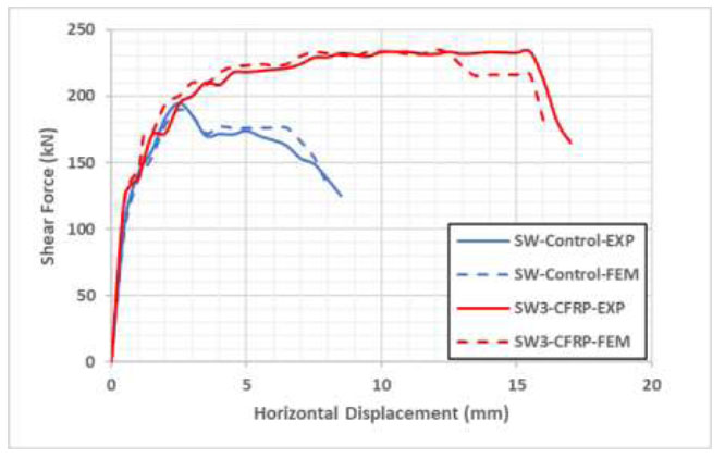
Load deflection curves for SW control and SW3-CFRP.
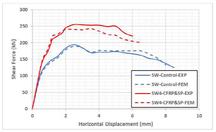
Load deflection curves for SW control and SW4-CFRP&SP.
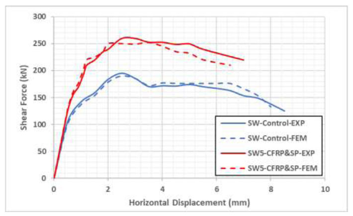
Load deflection curves for SW control and SW5-CFRP&SP.
Fig. ( 9) presents the load-deflection curves for the control specimen along with the second proposed retrofitting technique, which used both horizontal and diagonal CFRP strips with 200 mm width. The ultimate shear force capacity was increased by 23% (ultimate shear force before retrofitting 189.8 kN and 233 kN after retrofitting for this configuration).
The following Figs. ( 10 and 11) show the load-deflection curves of shear walls retrofitted employing both CFRP and steel plates compared to the SW control specimen. The ultimate shear capacity values were increased in both models, which suggests two different steel plate thickness values (1 and 1.5m) for the specimens SW4 and SW5, respectively. The control specimen's ultimate shear force value was found to be 190 kN, while the specimen SW5, which was repaired both in CFRP and steel plate, reached almost 262 kN. The difference is 72 kN, so the increase ratio = 72/190 = 38% was restored, and the increasing percentage was also found to be 34% for SW4. The stiffness of the RC shear wall specimens was increased, as presented in the following figures.
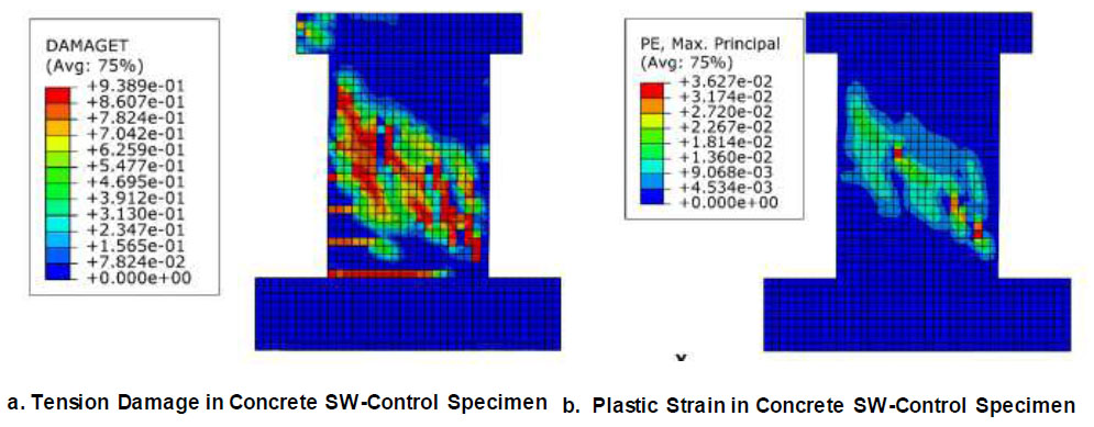
FE numerical model crack pattern and failure for SW-control specimen (without retrofitting).
4.2. Failure Modes
From the experimental and FE results, the diagonal tension failure (shear cracks) was intensified in the RC shear wall diagonal control specimen, as shown in Figs. ( 12 and 13). For specimens retrofitted with CFRP strips only, the mode of failure occurred at three stages. The first stage included horizontal flexural cracks followed by a second stage of debonding of CFRP strips and ended up with compression damage near the CFRP debonding location, as presented in Figs. ( 13 and 14). The shear wall specimens retrofitted using both CFRP and steel plates tend to fail in compression, as shown in Fig. ( 15). Table 9 presents the dominant mode of failure for each specimen.
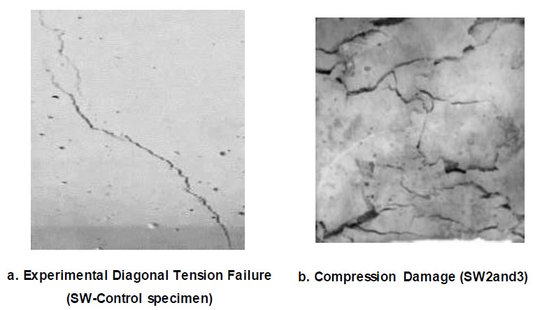
Experimental cracks before and after retrofitting.
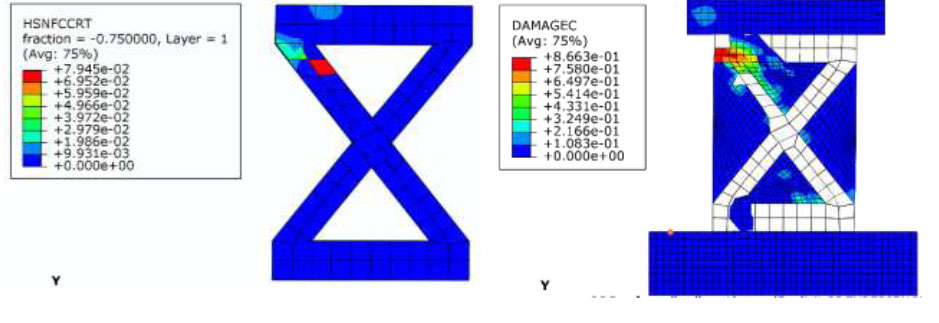
Compression damage in CFRP strips (location of debonding in red and compression damage in concrete) (failure for SW2-CFRP and SW3-CFRP).
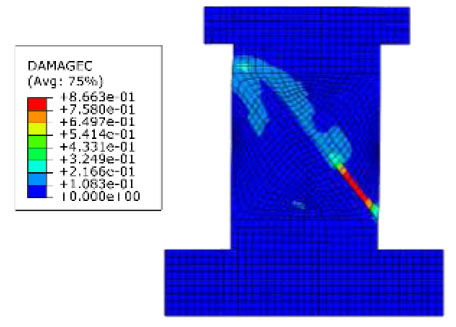
Compression failure of SW4and5-CFRP&SP.
| Specimen | Failure Mode |
|---|---|
| SW-Control | Diagonal Tension Failure (Shear Failure) |
| SW2-CFRP | Compression Failure + CFRP debonding |
| SW3-CFRP | Compression Failure + CFRP debonding |
| SW4-CFRP&SP | Compression Failure |
| SW5-CFRP&SP | Compression Failure |
| Specimen | ∆ y (mm) | ∆ u (mm) | Ductility Index (∆ u/∆ y) |
|---|---|---|---|
| SW1 | 1.5 | 9 | 6 |
| SW2-CFRP | 1.6 | 11 | 6.9 |
| SW3-CFRP | 2 | 17 | 8.5 |
| SW4-CFRP&SP | 1.7 | 7 | 4.12 |
| SW5-CFRP&SP | 1.7 | 7 | 4.12 |
4.3. Ductility
Ductility index values (the ultimate displacement divided by the yielding displacement) were calculated for each tested specimen. As mentioned before, it is an important area of study related to shear wall design. Ductility index values are shown in the following Table 10. It was found that the optimum retrofitting configuration in terms of ductility, the one which proposed horizontal and diagonal strips for the same specimen (SW3), while adding steel plates increased the stiffness of the tested specimens. On the other hand, it significantly reduced the ductility, to be less than the control specimen (SW1).
4.4. Effect of Steel Plate Thickness
One of the advantages of the FE model is the possibility of performing an effective parametric study, the thickness of the steel plate was studied here. 5 different thicknesses (2-7mm) were applied in the FE model, and the thicknesses (1 and 1.5mm) were studied experi- mentally. Fig. ( 16) presents the effect of steel plate thickness on the shear load capacity of strengthened walls. The optimum plate thickness value of 5 mm was found. Any thickness beyond 5mm tends to increase the stiffness of the shear walls and reduce the shear capacity significantly; the same result was found by Metwally [ 31].
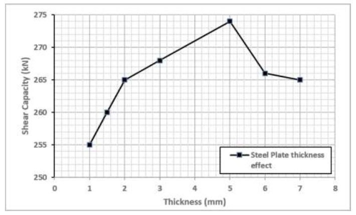
Effect of steel plate thickness.
CONCLUSION
In this paper, an experimental and FE numerical investigation using the commercial software Abaqus was conducted on five RC shear wall specimens, the following remarks can be concluded:
• The ultimate shear capacity was increased by 23% for CFRP retrofitted specimens using both diagonal and horizontal strips, and a 38% increase was found after adding a 1.5 mm steel plate to the existing retrofitting configuration.
• The CFRP debonding was the dominant mode of failure for the two tested specimens retrofitted using CFRP. The cohesive behavior adopted in the FE model captured the correct load-deflection curves along with the crack pattern observed experimentally. Compression failure occurred for specimens retrofitted using CFRP and steel plate.
• Ductility was increased by more than 40% for specimens retrofitted using CFRP diagonal and horizontal sheets compared to the control specimen.
• The optimum steel plate 5 mm thickness was found as any increase beyond this thickness will increase the stiffness and decrease both the ductility and the shear capacity.
• Further experimental and numerical modeling studies are required in this field to study the slipping of steel reinforcement bars in the shear wall specimens during the tests as well as discussing new strengthening techniques combined together (CFRP and UHPC) as a new proposed hybrid strengthening technique.
• Future studies are required in this field, especially, in the application of similar strengthening techniques (CFRP, steel plates, UHPC, etc) to damaged and corroded shear wall specimens.
AUTHORS’ CONTRIBUTION
The author confirms sole responsibility for the: study’s conception and design, data collection, analysis and interpretation of results, and manuscript preparation.
LIST OF ABBREVIATIONS
| CDP | = Concrete Damage Plasticity |
| RC | = Reinforced Concrete |
AVAILABILITY OF DATA AND MATERIALS
The data supporting the findings of the article is available in the ResearchGate at https://www.researchg ate.net/publication/383786603_Data_SW2024, reference number DOI: 10.13140/RG.2.2.28501.84963.
ACKNOWLEDGEMENTS
Declared none.

