All published articles of this journal are available on ScienceDirect.
Comparative Analysis of Common Structural Systems for Pedestrian Bridges in Kuwait
Abstract
Introduction
Pedestrian bridges are crucial urban infrastructure, providing safe passage over roads, railways, and waterways. Different structural systems like trusses, steel girders, and reinforced concrete beams are used, but more research is needed to determine the best design for specific regional contexts.
Methods
This research paper presents a comparison of various structural systems for pedestrian bridges, with a focus on a practical case study in Kuwait. The study evaluates five common pedestrian bridge designs: steel, concrete, and three truss arrangements. The designs were assessed based on multiple criteria, such as cost, construction time, structural weight, carbon emissions, and vibration performance. Using a decision-making matrix (DMM) and engineering judgment, Truss 3 (X-bracings without verticals) was identified as the optimal design. It features a unique bracing system that enhances its properties. Truss 3 was found to be the lightest design at 561.6 kN, with moderate CO2 emissions of 64.2 tons and a cost of 4288.5 KD per span. Detailed design and safety checks were conducted using ETABS software. The final design was detailed and presented using Autodesk Revit.
Results
The findings highlight the importance of using integrated frameworks and multi-criteria decision analysis (MCDA) to select suitable structural systems that meet technical and regional sustainability goals.
Conclusion
This research aims to provide a robust solution tailored to the unique conditions of Kuwait, ensuring safety, efficiency, and sustainability for pedestrian bridge infrastructure.
1. INTRODUCTION
The civil construction industry has a significant impact on the global economy and the environment. In 2021, it accounted for 34% of energy consumption and 37% of global carbon dioxide emissions [ 1 ]. As there is a growing focus on sustainability, it is important to develop efficient and eco-friendly solutions for infrastructure projects, including pedestrian bridges [ 2 ]. Optimization techniques are crucial in guiding the decision-making process in pedestrian bridge design, balancing technical, economic, and environmental factors. When considering pedestrian bridges, it is essential to optimize not only costs and environmental impacts but also the comfort of pedestrians, as increasing slenderness makes structures more susceptible to human-induced vibrations, which can cause discomfort and structural damage.
Pedestrian bridges can be built using different structural systems, such as trusses, steel beams, and reinforced concrete beams. A comprehensive evaluation of these systems is necessary to select the most appropriate option, considering important parameters such as vibration efficiency. This research addresses an important gap by comparing multiple structural systems for pedestrian bridges based on parameters such as cost, construction time, structure weight, carbon emissions, and vibration efficiency. It aims to provide customized and sustainable solutions for Kuwait's unique regional conditions.
2. LITERATURE REVIEW
This literature review explores the current research landscape in the pedestrian bridge area, highlighting the importance of different comparison criteria and bolstering the discourse with pertinent studies.
2.1. Cost
The cost is an essential consideration when selecting structural systems for pedestrian bridges. Several research studies emphasize the importance of cost analysis in bridge design, comparing the financial impli- cations of utilizing different materials and construction methods [3-6]. Cost factors encompass initial construction costs, ongoing maintenance expenses, and potential benefits from material efficiency and modular construction approaches [6-8].
2.2. Construction/manufacturing Time
The time needed to construct or manufacture a pedestrian bridge is crucial, particularly in urban areas where minimizing disruption is a priority. Research studies emphasize the advantages of prefabricated and modular bridge components, which can significantly reduce on-site construction time [9, 10]. Other studies also discussed the benefits of accelerated bridge construction techniques, which combine advanced materials and construction methods to expedite project timelines [11, 12].
2.3. Weight of the Structure
The design, foundation requirements, and overall material usage of a pedestrian bridge are significantly impacted by its weight. Lighter structures offer several advantages, including easier installation and reduced foundation costs [12, 13]. Several research studies examined different structural systems, such as steel, aluminum, and composite materials, with a focus on their weight-to-strength ratios and their implications for bridge design [14-17].
2.4. Carbon Emission
The significance of sustainability and environmental considerations in construction projects is on the rise. Carbon emissions linked to the production, transportation, and installation of bridge materials are key considerations. Several studies were conducted to delve into the carbon footprint of different bridge materials, promoting the adoption of low-emission alternatives like recycled steel and sustainable composites [18-22]. Furthermore, lifecycle assessment (LCA) methodologies are employed to assess the enduring environmental effects of various structural systems [18-22].
2.5. Vibration
The vibration performance of pedestrian bridges is essential for both user comfort and structural integrity. Bridges with poor vibration characteristics can cause discomfort for users and potential structural damage over time. Several studies focused on the dynamic behavior of pedestrian bridges, comparing the vibration performance of various structural systems and materials [23-26]. These studies emphasize the importance of including vibration control measures, such as tuned mass dampers and base isolation techniques, in bridge design [23-26].
2.6. Integration of Multiple Criteria
The importance of using a multi-criteria approach in comparing pedestrian bridge structural systems is clear. Integrated frameworks that take into account cost, construction time, weight, carbon emissions, and vibration performance offer a comprehensive perspective, allowing for better decision-making. Research studies illustrated the use of multi-criteria decision analysis (MCDA) in bridge design, demonstrating how these tools can balance competing priorities and optimize overall performance [27-29].
2.7. Summary of Findings and Identification of Research Gap
The analysis of pedestrian bridge structural systems is a complex task that involves considering multiple criteria such as cost, construction time, structural weight, carbon emissions, and vibration performance. Utilizing a multi-criteria approach is essential in this context. Various research studies showed the effectiveness of multi-criteria decision analysis (MCDA) in pedestrian bridge design, demonstrating how MCDA tools can balance competing priorities and optimize overall performance for better decision-making [30-32].
Addressing these criteria through integrated frameworks and MCDA can significantly improve the efficiency, sustainability, and user experience of pedestrian bridges. However, there is a research gap in applying these methodologies to specific regional contexts, such as Kuwait. The unique environmental, economic, and social conditions in Kuwait necessitate tailored research to develop suitable structural systems for pedestrian bridges. Therefore, this research focuses on leveraging integrated frameworks and MCDA to aid in the selection of appropriate structural systems for pedestrian bridges in Kuwait. It aims to incorporate region-specific factors and constraints, ensuring that the resulting bridge designs are not only technically sound but also aligned with local sustainability and performance goals.
3. SELECTION OF CASE STUDY
The crowdedness in Al-Salmiya is a big concern. The Al-Jawazat roundabout is particularly problematic, being both dangerous and congested. Unfortunately, it seems that the planning for this roundabout didn't properly consider the potential future traffic in nearby areas like the Albidaa roundabout. With more foreigners coming to Kuwait, many of whom prefer walking and cycling, the need for alternative modes of transportation is becoming more apparent. To address these issues and meet the safety requirements of pedestrians and cyclists, we are going to apply our basic knowledge and skills to design innovative and sustainable pedestrian bridges. The study's main objective is to tackle this problem by examining various types of steel truss sections, designs for pedestrian bridges, and potential construction issues like vibrations caused by human activity. By incorporating these elements while adhering to regulatory standards. One proposed solution is to design a unique circular pedestrian bridge with multiple entry points and innovative features that promote sustainability and address pedestrian safety concerns in this vibrant coastal area, as you can see in Fig. (1).
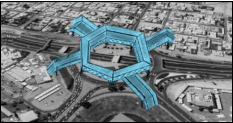
Google earth capture with proposed bridge design shape.
4. DESIGN CONSTRAINTS AND CONSIDERATIONS
4.1. Dimensions
For this case study, we will focus on a 32-meter-long bridge segment. This length was chosen to minimize any disruption to the main road. The clearance height of the bridge is 6 meters, as specified by the Ministry of Public Works in Kuwait. The width of the bridge is 4 meters. The overall diameter is 150.6 meters, based on the diameter of the Al-Jawazat roundabout.
4.2. Loads
Three load cases—dead load, live load, and wind load—were carefully considered for the design of the proposed structural system for the bridge. These load cases were then combined using load combinations as specified in ASCE7-16, ensuring that the structural system is designed to withstand a variety of potential loads and forces. This approach allows for a comprehensive and robust design that meets safety and structural integrity requirements.
4.2.1. Dead Load
The dead load applied to the structures was calculated by considering the following parameters:
- Unit weight of concrete: 24 kN/m3 [33]
- For steel structural systems for truss options and steel framing systems, ComFlor® 60 with a 0.9 mm metal deck was used for the flooring. This system has a 125mm normal-weight concrete slab depth with a 0.9mm metal deck [34]. The slab was modeled in ETABS as a one-way membrane slab element with 0.9mm thickness. A dead load of 3 kN/m2 (Calculated as 0.125m thickness × 24 kN/m3 unit weight) was applied to account for the weight of the concrete topping.
- A service weight of 0.5 kN/m2 was applied as a dead load to account for railing and any other mechanical and electrical services [35]. This load was applied to all proposed design options.
- For the precast concrete option, a solid slab of 200mm thickness was used.
4.2.3. Wind Load
When calculating wind loading on a structure, numerous key parameters are taken into consideration to ensure an accurate and conservative layout. Wind speed is a critical component, and it is used at 21.5 m/s [37]. The velocity pressure coefficient (kz) is 1.04, which adjusts the wind stress based on the height of the structure. The topographic component (kzt) is thought to be 1, indicating a flat ground floor with no sizable topographical features that might expand wind results. Additionally, the wind directionality factor (kd) is 1, assuming the wind can impact the structure from any path uniformly. The floor elevation element (ke) is conservatively set to at least one, accounting for widespread atmospheric strain at sea level. With these parameters, the design wind pressure (qz) is calculated to be 294.69 N/m2 in accordance with ASCE7-16 [38], representing the force according to the unit vicinity that the structure ought to face up to underneath the specified wind situations.
5. METHODOLOGY
A site investigation was carried out using Google Earth. Subsequently, five preliminary designs were proposed which are three different truss bridges, a concrete bridge, and a steel bridge. The designs were analyzed using ETABS and verified according to applicable pedestrian bridge standards and codes, which are ACI 318-19 [39], AISC [40], and ASCE7-16 [38]. After that, the selected truss bridge was compared with both the steel and concrete bridges using a decision-making matrix. The criteria were carefully evaluated, and ultimately, the third truss bridge was selected for further development due to its superior combination of structural performance, sustainability, and innovative features. Detailed design work was then completed, including a structural analysis using ETABS, as well as modeling and design drawings created in Revit.
Fig. (2) outlines a systematic approach to designing a structural device, commencing with a site analysis using Google Earth. This initial step ensures a comprehensive understanding of the site conditions and layout. Following the analysis, the site's organization is examined to determine the optimal configuration for the structure. This process leads to the development of three distinct design alternatives: Design Option 1 (Precast Concrete System), Design Option 2 (Steel Girder System), and Design Option 3 (Truss System), each representing a unique structural approach tailored to the specific site and project requirements.
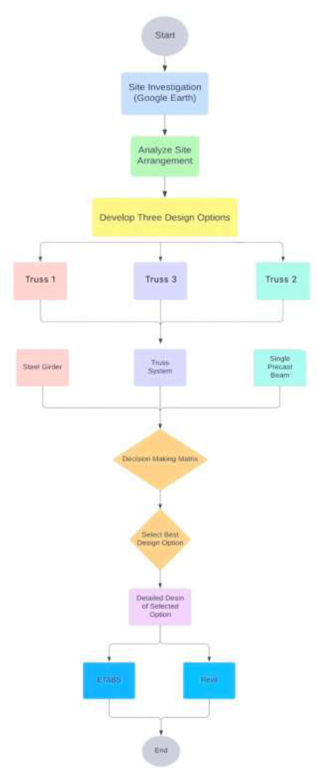
Flowchart representing the process of selecting final design.
Subsequently, a decision-making matrix is used to evaluate and compare the three design options based on various criteria, including cost, feasibility, and per- formance. The best design alternative is selected through this rigorous evaluation process. Once the ideal design is chosen, detailed design work for the selected option is conducted using ETABS and Revit. ETABS is employed for structural analysis and detailing to ensure compliance with relevant standards, while Revit is utilized for 3D visualization and integration with Building Information Modeling (BIM) technology. This comprehensive approach ensures that the final design is not only structurally sound but also effectively implemented and visually well-integrated.
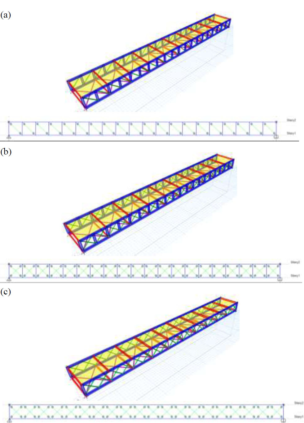
Proposed 3 truss design options. (a) Truss design option 1, (b) Truss design option 2, and (c) truss design option 3.
6. RESULTS
6.1. Design Optimization Results of the Structural System Options
Five designs were analyzed using ETABS software. The five design options are shown in Figs. (3 and 4). The five design options represent the most common structural systems that are used in Kuwait for pedestrian bridges. These options were modeled in structural analysis commercial software “ETABS”. They were obtained in compliance with standards and codes which are ACI 318-19 [39] and AISC [40] with ASCE7 [38] for the minimum applied loads as listed in section 4.2. They were verified in terms of design safety by the ratio of applied load to the capacity and the design sections were summarized in Table 1.
6.2. Results Summary and Comparison of the Structural System Options
The subsections below show the summary of comparison results between the 5 designs. They were compared in terms of material cost, the weight of the structure, vertical deflection, lateral deflection, shear, moment, CO2 emissions, natural frequency, and natural period.
6.2.1. Cost of Material
Design Option 3, a truss bridge, emerges as the most cost-effective option at 4288.5 KD per segment. The cost is based on materials costs plus the cost of steel connections [ 41 ]. The concrete bridge design falls in the middle at 5100.9 KD per segment, while Design Option 2, a steel bridge, proves to be the most expensive at 5302.3 KD per segment due to the higher material quantity and additional connection costs [ 41 ]. The cost analysis was based on the self-weight of the section, assuming a steel price of 191 KD/ton [ 42 ] and a concrete price of 19.5 KD/metric volume. The total weight of each material was multiplied by the respective price per unit. When calculating the steel cost, we factored in 15% of steel weight to account for additional structural joints [ 42 ].
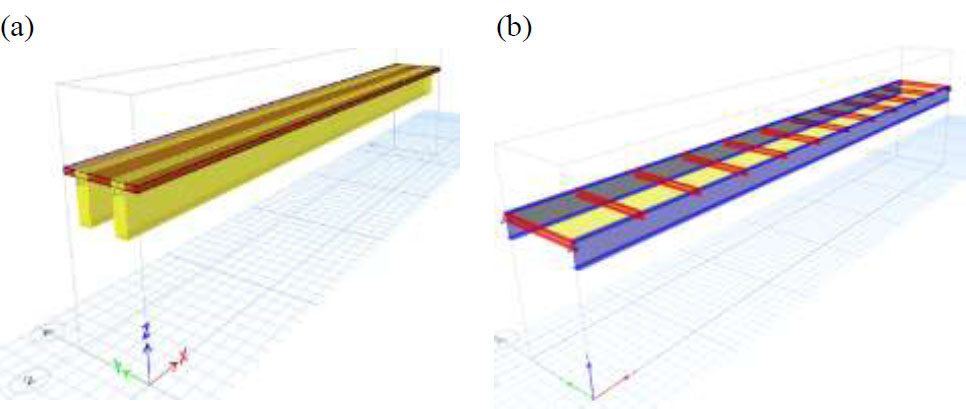
Proposed 2 common design options. (a) Precast concrete beam system and (b) Steel framing system.
| Section Types | Reinforced Concrete Bridge | Steel Girder Bridge | Truss Design (1) | Truss Design (2) | Truss Design (3) |
|---|---|---|---|---|---|
| Main beams | B600x1750 (Yellow) |
HE1000B (Dark blue) | HE240B (Dark blue) |
HE240B (Dark blue) |
HE240B (Dark blue) |
| Secondary beams | - | IPE270 (Red) |
IPE270 (Red) |
IPE270 (Red) |
IPE270 (Red) |
| Slab | S200 (Brown) |
CS125 (Yellow) |
CS125 (Yellow) |
CS125 (Yellow) |
CS125 (Yellow) |
| Vertical diagonal bracings | - | - | CHHF114.3x 6.3 (Green) |
CHHF88.9x5 (Green) |
CHHF114.3x 4 (Green) |
| Wind horizontal bracings | - | - | CHHF114.3x 3.2 (Purple) |
CHHF114.3x 3.2 (Purple) |
CHHF114.3x3.2 (Purple) |
6.2.2. Construction Manufacturing Time
Three bridge designs are being considered: concrete, steel, and truss. The steel bridge design is the quickest to construct because it will be prefabricated off-site and ordered from a factory. The concrete bridge design takes longer as it requires 28 days of curing after ordering. The truss bridge design, which uses steelwork and composite steel deck, requires less time because the concrete slabs can be made on-site, and the steel can be pre-ordered based on the required dimensions.
When estimating the manufacturing time for structural systems, several factors need to be considered, such as design complexity, fabrication process, and assembly time. The manufacturing process involves cutting, welding, and drilling and typically takes about one week at a production rate of 10 tons per day. Therefore, the time required for steel options was calculated based on the total weight of the system divided by 10 tons per day.
To determine the time needed to manufacture reinforced concrete beams, we start by calculating the volume of concrete, which is 63 m 3 for two beams that are 600 mm wide, 1750 mm deep, and 30 meters long. It takes approximately 4 days for a 4-worker team to place the reinforcement and pour concrete. Installing and removing the formwork for 2 beams takes 2 days, and the formwork needs to be removed after 7 days of curing. Overall, the total manufacturing and curing operations for the reinforced concrete beams are estimated to take about 13 days. It is worth mentioning that these production rates were obtained by interviewing site engineers in Kuwait.
6.2.3. Weight of the Structure
The truss design is considered the lightest of all the designs, which is 561.6 kN. Steel design falls in between and weights 606.9 kN, and finally, concrete design bridge has the highest weight, which is 2186.7 kN. The total material weight of each design was obtained by obtaining the self-weight by summing the vertical reactions at the four support corners of the bridge. We summed the reactions which represent the weight of the total section bridge. Then, the assumption was made mostly for concrete, where we obtained its parameters from ETABS, such as the area of the slab, which was 128m2, the thickness of 125mm, and the unit weight of concrete of 24kN/m2 [43]. We obtained that the total concrete was 128(125/1000) *24 to get a value of 384kN of total concrete, which is 39143.7kg of total concrete in the section. For the steel model, we summed up the reactions of FZ.
6.2.4. CO2 Emissions
Design option 2, which is the steel bridge design, is the least designed to affect the environment adversely as it produces the least CO2 emissions, which is 31.8 tons [44]. While design option 3, which is a truss bridge, falls in the middle between concrete and steel, which is 64.2 tons. Finally, concrete design has the highest CO2 among all designs which is 221.135 tons. It was calculated by assuming that each ton of steel will produce 1.4 tons of CO2 and each kilogram of concrete will produce 0.9kg of CO2 [44]. With the total weight of each concrete and steel, we obtained the value from substitution with the values per unit.
6.2.5. Natural Frequency and Natural Period
The steel bridge design is considered the best in terms of structural integrity because it was found to have the lowest natural frequency and the highest natural period. On the other hand, the truss bridge design's natural frequency and natural period fall in between those of concrete and steel designs. Therefore, the concrete design has the highest natural frequency but the lowest natural period. It's important to note that the natural frequency was measured in the vertical direction and the natural period values were measured in the horizontal direction.
6.2.6. Vertical and Lateral Deflections
The truss design bridge has the lowest vertical deflection and the highest lateral deflection. On the other hand, a steel design bridge has the highest vertical deflection due to its flexibility, and its lateral deflection falls between the two other designs. Finally, a concrete design has the highest lateral deflection but an intermediate vertical deflection.
Fig. (5) illustrates a comprehensive comparison of the 5 designs, evaluating them across different criteria such as performance, cost, and other criteria that were discussed above.
6.3. Multi-criteria Decision Analysis (MCDA)
A multi-criteria decision-making matrix is a chart that allows a group or an individual to systematically identify, evaluate, and rank the relationships between different sets of data. The matrix is especially useful for assessing a large number of decision variables and determining the relative importance of each item.
One of the most significant benefits of the decision matrix is that it enables us to introspect and evaluate our judgments with minimal bias. This approach also helps in making complex and difficult decisions. Additionally, a decision matrix allows us to prioritize tasks, build arguments, and solve problems to justify previous decisions. Procedure for multi-criteria decision-making matrix:
(1) Create a list of relevant evaluation criteria for the situation.
(2) Discuss and refine the list of criteria. Determine which criteria are mandatory and which ones are optional. Choose only the criteria that the team or individual considers most important from the entire list.
(3) Assign a relative weight to each criterion based on its significance in the context.
(4) Create an L-shaped matrix. Label the list of alternatives with the criteria along one edge. See Fig. (6).
(5) Compare each option against the criteria.
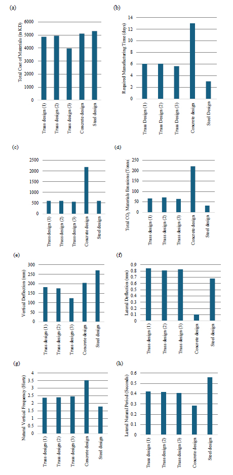
Comparison between the 5 designs in terms of different criteria.
In this context, we compared three different types of truss designs to select the best one based on our specific criteria as shown in Table 2. Subsequently, we compared the chosen truss design with two other designs (steel bridge and concrete bridge) based on the same criteria to determine the most recommended option from economic and environmental as is shown in Table 3, and social impact perspectives. The selection will be made using the Multi-Criteria Decision-Making Matrix Analysis method (MCDA) discussed earlier. We will begin with pairwise comparisons and continue until the selection using tables and figures to clearly illustrate the methodology. Our relevant criteria include cost of materials, construction speed, structure weight, CO2 emissions, natural frequency (vibration), vertical deflection, lateral deflection, and natural period. A summary of the comparison between the 5 designs using the MCDA method is shown in Fig. (7).
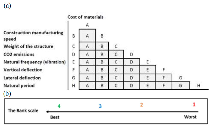
Decision-making matrix process for best design selection. (a) L-shaped matrix and (b) Numeric rank scale.
| - | - | - | Truss | 1 | Truss | 2 | Truss | 3 |
|---|---|---|---|---|---|---|---|---|
| S. No. | Criteria | Weight | Rating | Score | Rating | Score | Rating | Score |
| 1. | Cost of materials | 0.8 | 3 | 2.4 | 2 | 1.4 | 4 | 3.2 |
| 2. | Construction manufacturing speed | 0.7 | 2 | 1.4 | 2 | 1.4 | 2 | 1.4 |
| 3. | Weight of the structure | 0.6 | 3 | 1.8 | 2 | 1.2 | 4 | 2.4 |
| 4. | CO2 emissions | 0.5 | 2 | 1 | 2 | 1 | 2 | 1 |
| 5. | Natural frequency (vibration) | 0.4 | 3 | 1.2 | 2 | 0.8 | 2 | 0.8 |
| 6. | Vertical deflection | 0.3 | 1 | 0.3 | 2 | 0.6 | 3 | 0.9 |
| 7. | Lateral deflection | 0.2 | 1 | 0.2 | 3 | 0.6 | 2 | 0.4 |
| 8. | Natural period | 0.1 | 3 | 0.3 | 2 | 0.2 | 2 | 0.2 |
| TOTAL | - | - | 8.6 | - | 7.2 | - | 10.3 | |
| - | - | - | Concrete | 1 | Steel | 2 | Truss | 3 |
|---|---|---|---|---|---|---|---|---|
| S. No. | Criteria | Weight | Rating | Score | Rating | Score | Rating | Score |
| 1. | 1. Cost of materials | 0.8 | 3 | 2.4 | 2 | 1.6 | 4 | 3.2 |
| 2. | 2. Construction manufacturing speed | 0.7 | 2 | 1.4 | 4 | 2.8 | 3 | 2.1 |
| 3. | 3. Weight of the structure | 0.6 | 1 | 0.6 | 3 | 1.8 | 4 | 2.4 |
| 4. | 4. CO2 emissions | 0.5 | 1 | 0.5 | 3 | 1.5 | 2 | 1 |
| 5. | 5. Natural frequency (vibration) | 0.4 | 1 | 0.5 | 4 | 2 | 3 | 1.5 |
| 6. | 6. Vertical deflection | 0.3 | 3 | 0.9 | 2 | 0.6 | 4 | 1.2 |
| 7. | 7. Lateral deflection | 0.2 | 4 | 0.8 | 3 | 0.6 | 2 | 0.4 |
| 8. | 8. Natural period | 0.1 | 1 | 0.1 | 3 | 0.3 | 2 | 0.2 |
| TOTAL | - | - | 7.2 | - | 11.2 | - | 12 | |
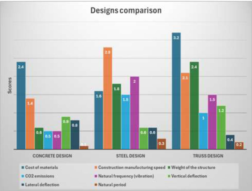
Summary of comparison between the 5 designs using the MCDA method.
The study involved comparing three different truss arrangements with varied configurations, as detailed in Table 2 . The most optimal truss design, referred to as the reference solution, was then evaluated against steel and concrete using MCDA, as presented in Table 3 . Each criterion was assigned specific weights based on its relative importance, ranging from 8% to 1%. The resulting scores for the concrete, steel, and truss designs were 7.2, 11.2, and 12, respectively. This indicates that truss arrangement 3 emerged as the most favorable design.
7. DISCUSSION
7.1. Comparison between Proposed Structural Systems for Pedestrian Bridges
The comparative evaluation of concrete, steel, and truss designs reveals distinct benefits and barriers across several key overall performance metrics. Truss design incurs the best material charges but justifies this with superior structural efficiency and lengthy-term durability. While steel design offers the quickest construction velocity and lowest CO2 emissions, truss design provides a balanced manufacturing system suited to environmental impact and premier weight for structural balance. All designs show good structural stiffness, with truss design presenting the essential flexibility for numerous architectural applications.
Truss design is particularly suitable for pedestrian bridges because of its inherent structural efficiency, aesthetic versatility, and powerful load distribution. The triangular geometry of truss structures ensures even load distribution, reducing pressure concentrations and enhancing sturdiness. Additionally, truss design permits significant architectural flexibility, allowing the bridge to blend with or enhance the surrounding environment. This design also enables simpler inspection and renovation, contributing to a longer service life with lower maintenance costs.
Considering the benefits of truss design, it would be the superior choice for pedestrian bridges. Despite higher initial costs, the long-term benefits of structural efficiency, durability, reduced maintenance, and overall lifecycle cost make it a profitable investment. Truss design meets functional requirements while offering the potential for iconic, sustainable systems that serve communities effectively over many years.
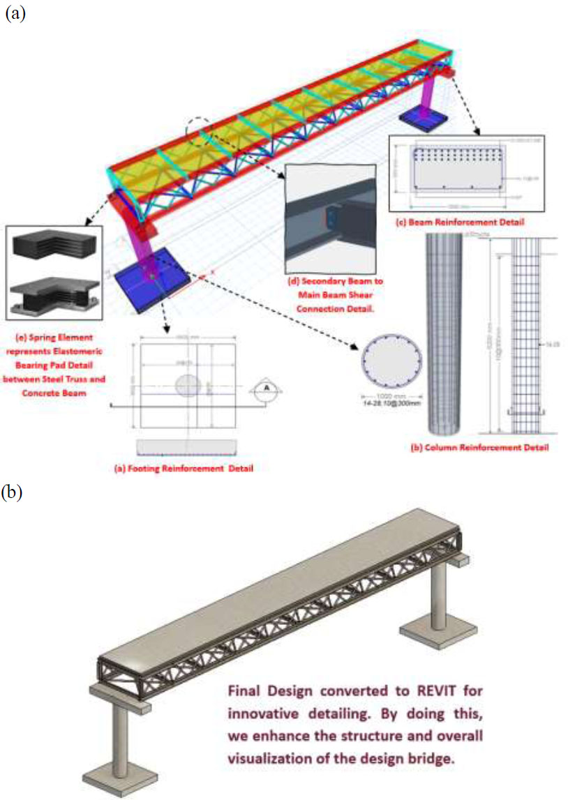
Design details of the selected design using (a) ETABS Software and (b) Autodesk Revit.
7.2. Final Design Process and Detailing
Fig. (8a) shows a detailed structural layout created using ETABS, in compliance with ACI 318-22 and AISC 360-LRFD 2016 standards. The design includes footing, column, and beam reinforcement, shear connection information, and elastomeric bearing pads to ensure structural integrity, load distribution, and balance. The process emphasizes meticulous detailing using advanced ETABS tools, integrating steel trusses supported by reinforced concrete, and showcasing a hybrid approach that leverages the strengths of both materials.
Furthermore, the structural model was transferred to Revit using the CSI XRevit tool, enabling 3D visualization and integration with Building Information Modeling (BIM) technology as is shown in Fig. (8b). This transfer enhances the design process by improving visualization, coordination, and collaboration. The combination of ETABS for structural analysis and Revit for BIM exemplifies modern engineering practices that ensure accurate, efficient, and compliant structural designs. This approach not only adheres to industry standards but also promotes efficient project management and delivery.
CONCLUSION
To conclude, this project provided a comparison between different structural systems for pedestrian bridges in Kuwait. We studied different types of pedestrian bridges and considered factors like vibration. We also studied various codes such as ACI 318, AISC 2016, and ASCE7 2016 to design our bridges. The decision-making matrix includes criteria such as cost of materials, construction manufacturing speed, weight of the structure, CO2 emissions, natural frequency (vibration), vertical deflection, lateral deflection, natural period, and internal forces in critical members and weighted them based on their importance. We designed 5 designs 3 trusses, a concrete bridge, and a steel bridge. First, we compared 3 trusses to select the optimum design. After comparing three different truss designs, we found that truss 3 is 17% less than truss 1in price, and 18.3% less than truss 2 in price. Truss 3 outperformed truss 1 and 2, making it the best choice due to its lower cost and lighter weight. Then, we compared the chosen truss with steel and concrete bridge. The truss scored highest in terms of cost-effectiveness and weight. However, it did have a slightly higher lateral deflection of 0.827mm compared to the steel bridge's 0.68mm and the concrete bridge's 0.104mm. On the other hand, the truss exhibited the lowest vertical deflection. The Decision-Making Matrix method (DMMA) helped us make an informed decision.
For future research, exploring extra structural structures and configurations of trusses is recommended to beautify the versatility and overall performance of pedestrian bridge designs. This should include reading diverse truss geometries, hybrid materials, and revolutionary production techniques to pick out the most green and cost-effective answers. Additionally, measuring the vibrational performance of those structural systems below human-triggered vibrations the usage of step evaluation can offer treasured insights into their dynamic behavior and comfort degrees for users. Incorporating superior existence cycle evaluation (LCA) will similarly advantage the research by assessing the environmental effects, financial feasibility, and lengthy-term sustainability of different design options. This holistic approach will help in growing optimized, resilient, and green pedestrian bridges that meet the needs of current infrastructure. It is also recommended that experimental data be conducted and collected to support the numerical findings.
AUTHORS' CONTRIBUTION
It is hereby acknowledged that all authors have accepted responsibility for the manuscript's content and consented to its submission. They have meticulously reviewed all results and unanimously approved the final version of the manuscript.
LIST OF ABBREVIATIONS
| DMMA | = Decision-Making Matrix method |
| MCDA | = Multi-criteria Decision Analysis |
| BIM | = Building Information Modeling |


