All published articles of this journal are available on ScienceDirect.

Structural Response of Post-tensioned Slabs Reinforced with Forta-Ferro Under Impact Load: Experimental and Numerical Approach
Abstract
Background
Construction projects in mountainous regions are increasingly confronted with challenges posed by rockfall hazards, which have become more severe due to environmental changes, including deforestation and landslides.These risks threaten infrastructure integrity and human safety, necessitating the integration of impact-resistant features into structural designs. In this context, enhancing the structural response of post-tensioned slabs under impact loads is a critical area of study.
Objective
This research investigates the effectiveness of incorporating Forta-Ferro fibers into concrete mixes to improve the impact resistance of post-tensioned slabs. The aim is to evaluate whether fiber-reinforced concrete offers better structural performance under dynamic loading conditions, thereby contributing to safer and more resilient construction in hazard-prone areas.
Methods
Two geometrically identical slabs (1.5 m × 3.3 m × 0.18 m) were prepared. The first slab was cast using conventional concrete, while the second was cast using the same mix with an addition of 0.4% by volume Forta-Ferro fibers. Both slabs were subjected to a central impact using a 600 kg steel ball dropped freely from a height of 8 meters. Additionally, three-dimensional finite element models were developed to simulate the slabs’ behavior under the same loading conditions.
Results
Experimental results demonstrated that the slab incorporating Forta-Ferro fibers exhibited enhanced performance, including reduced displacement, improved crack distribution, and less overall damage. Comparison with finite element simulations confirmed the accuracy of the numerical model in capturing the real behavior of the slabs.
Conclusion
The inclusion of Forta-Ferro fibers significantly improves the impact resistance of post-tensioned slabs. The proposed fiber-reinforced design provides a viable solution for enhancing structural response under dynamic loading, with experimental and numerical results in strong agreement.
1. INTRODUCTION
Rockfalls present considerable hazards to structures in mountainous areas, requiring comprehension, mitigation techniques, and thorough geological evaluations. Fiber-reinforced concrete is acknowledged as an exceptional solution for augmenting concrete performance under impact, providing enhanced resistance to localized damage and increased energy absorption relative to traditional reinforced concrete.
Recent research on the integration of forta-ferro fibers into concrete formulations has demonstrated substantial enhancements in mechanical characteristics and stability. Dashti et al. [1] showed that the incorporation of forta-ferro fibers at a 0.4% volume fraction can augment compressive strength by 15% and markedly improve direct tensile strength. This leads to reduced crack propagation and enhances the overall ductility of the concrete. The incorporation of forta-ferro fibers in Ultra High-Performance Self-Compacting Concrete (UHPSCC) has resulted in a 1% to 7% augmentation in compressive strength, a 20% to 30% improvement in tensile strength, and a 16% to 26% increase in flexural strength, revealing the fibers' ability to enhance toughness and mitigate cracking under stress [2]. Investigations on the compressive and flexural characteristics of forta-ferro fiber-reinforced concrete have demonstrated a notable enhancement in compressive strength, varying from 10% to 20%, suggesting that these fibers may function as a non-corrosive substitute for steel reinforcement in specific applications [3]. The use of forta-ferro fibers in concrete with compressed nylon aggregates demonstrated enhanced durability and mechanical properties, hence augmenting resistance to environmental degradation and improving the material's toughness and lifetime [4]. Alfoul et al. [5] found that the inclusion of forta-ferro fibers in concrete markedly improves durability and lifetime by promoting more uniform stress distribution, hence diminishing the possibility of catastrophic failure. While forta-ferro fibers significantly enhance compressive and tensile strengths, they may not entirely replace steel fibers for flexural strength. Comparative studies demonstrate that although forta-ferro fibers markedly improve compressive and tensile properties, steel fibers surpass them in flexural strength, suggesting that a hybrid method employing both types of fibers may be ideal for applications requiring elevated flexural strength [6]. Furthermore, a 0.4% volume percentage of forta-ferro fibers is recommended as ideal for enhancing compressive and tensile strength without compromising workability, underscoring the need for a balanced approach in augmenting mechanical qualities while maintaining ease of mixing and application [7, 8].
The research on impact has predominantly concentrated on reinforced concrete slabs. The research on the behavior of post-tensioned slabs under impact is sparse. Recently, post-tensioned slabs have become increasingly favored due to their superior characteristics relative to reinforced concrete slabs. These characteristics are demonstrated in enhanced span capacity, long-term cost efficiency through reduced maintenance, optimized material usage, increased durability and crack resistance, accelerated construction timelines, improved resilience to seismic and wind forces, and sustainability benefits through minimized environmental impact. A recent study conducted by Rawi et al. compared the response of post-tensioned slabs subjected to impact loads to RC slabs under the same impact loading [9]. The study showed that post-tensioned slabs had lower displacements and higher impact force compared to RC slabs. A subsequent investigation by the authors of this paper with Jahami et al. [10] showed that rehabilitated post-tensioned slabs using shear reinforcement in the form of ties had improved performance under impact load. Additionally, research by Li et al. [11] investigated the role of diaphragms and concrete-filled steel tube trusses (CFSTTs) in enhancing the transverse connectivity and load distribution of prestressed concrete box girder bridges. Their findings highlight the importance of incorporating advanced reinforcement techniques to mitigate structural vulnerabilities and improve load-bearing performance. While this study focused on bridges, its insights highlight the potential of integrating alternative reinforcement strategies, such as fiber reinforcement, in post-tensioned slab systems subjected to impact loads, which remains a topic worth investigation.
Numerous researchers have conducted finite element simulations of various impact loading scenarios utilizing commercial finite element software such as ABAQUS [12-16] and LS-DYNA [17, 18]. The Holmquist-Johnson-Cook (HJC) [19] and Johnson-Cook (JC) [20] material models are widely utilized for simulating the behavior of concrete and steel materials, respectively, under conditions of significant strain, elevated strain rates and high pressures induced by drop weight and ballistic impacts. Rajput and Iqbal [13] conducted numerical simulation of the ballistic performance of plain, reinforced and prestressed concrete plates incorporating the behavior of concrete and steel reinforcement through the HJC and JC constitutive models, respectively. The computer simulations accurately forecasted the ballistic limit of the three concrete types; nevertheless, the formation of cracks in the concrete could not be replicated. Kezmane et al. [16] conducted numerical simulations of the low-velocity impact response of reinforced concrete slabs with yielding supports, utilizing the Concrete-Damage-Plasticity (CDP) model for concrete and the Balarbi material model for steel reinforcement. While the CDP model accurately replicated the concrete degradation in alignment with the real results, the necessity for more advanced material and computational modeling for such issues was highlighted. In addition, a study [13] performed computational validation of low-velocity impact testing on 100mm thick reinforced concrete plates utilizing the CDP and classical metal-plasticity models. The conclusion reached is that for a dynamic numerical issue, the CDP model must be integrated with a fracture energy criterion, and a mesh size with a unity aspect ratio should be utilized. The incorporation of damage and strain rate effects is essential for accurately forecasting structural behavior. Moreover, Mazars, Rouquand, and Pontiroli [21] proposed a coupled damage and plasticity model that accounts for stiffness deterioration, strain rate effects, and crack dynamics, validated through finite element simulations. Similarly, Berthet-Rambaud et al. [22] focused on a novel rock-fall protection system with fuse-supported roof slabs, effectively mitigating damage through localized impact absorption, as confirmed by experimental and numerical analyses. Rouquand, Pontiroli, and Mazars [23] extend the modeling framework by integrating damage and plasticity concepts to simulate severe loading scenarios, including pore collapse and shear plasticity, achieving computational efficiency with explicit finite element procedures. Collectively, these studies highlight innovative numerical strategies for predicting the structural response of concrete elements subjected to extreme dynamic loads. Though these models have proposed coupled damage-plasticity models to enhance predictive accuracy, these techniques have to be systematically applied to fiber-reinforced PT slabs under impact loading.
This study addresses the gap in research on fiber-reinforced post-tensioned slabs by evaluating the impact resistance of post-tensioned slabs incorporating Forta-Ferro fibers at an optimal 0.4% volume fraction, a percentage suggested by prior research for optimal tensile strength and satisfactory workability. The investigation aims to compare the performance of ordinary post-tensioned slabs and forta-ferro-reinforced post-tensioned slabs under impact loading. The study demonstrates advantageous outcomes for the application of forta-ferro in regions susceptible to impact risks, as emphasized in the conclusion of this work, illustrating how forta-ferro enhances the structural integrity of post-tensioned slabs subjected to impact loads. A finite element model was built using the advanced software ABAQUS to model materials and consider the material non-linearity, stiffness degradation and strain effects. The model is calibrated using the control slab. The results between the experimental and numerical models are compared to check the possibility of using a finite element model to predict the dynamic response of impacted post-tensioned slabs with and without forta-ferro fibers.
2. DATA AND METHODS
2.1. Forta-Ferro Properties
Forta-Ferro (Fig. 1) is a macro synthetic fiber made from virgin copolymer/polypropylene, valued for its durability, ease of use, and ability to enhance concrete’s structural integrity by reducing temperature and shrinkage-related cracking. Synthetic fibers are cheaper than steel and require less labor force. Its non-corrosive nature provides long life to the concrete structure as well. In this study, a 0.4% volume ratio of these fibers was added to the concrete before casting S2. This dosage was chosen based on the recommendations from the literature review. The length of the fiber is 54 mm. It has a density of 910 kg/m3, so it is considered low weight compared to steel fibers.
A ready-mix concrete of compressive strength 34 MPa at 28 days was used to cast the two slabs. Tests conducted at 28 days showed that the addition of fibers improved the concrete's ductility and tensile strength (Figs. 2 and 3).
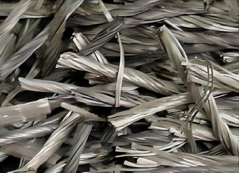
Forta-ferro fibers.
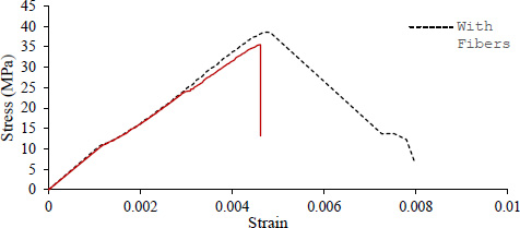
Compressive strength of cylinders with and without fibers.
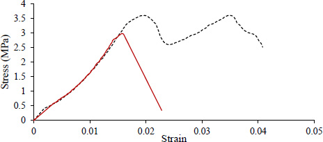
Tensile splitting test results for cylinders with and without fibers.
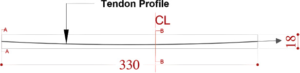
Slabs dimensions and tendon profile.
2.2. Experimental Setup
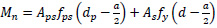
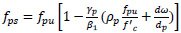
Two identical slabs, each measuring 3.3 x 1.5 x 0.18 meters (Fig. 4), were constructed for the experiment—one functioning as a control without fiber reinforcement (S1) and the other containing 0.4% Forta-Ferro fibers by volume (S2). The slabs were designed based on the ACI Building Code, with detailed moment capacity calculations guiding the selection of reinforcement. The moment capacity of each slab was calculated based on Eqs. (1 and 2):
 |
(1) |
 |
(2) |
Where “fps”is the stress in the pre-stressed reinforcement at nominal strength, “fpu” is specified tensile strength of pre-stressing tendons, “dp” distance from the extreme compression fiber to the centroid of the pre-stressed reinforcement but not less than 80% of the overall slab’s thickness “γp” is a factor based on the criteria (fpy = 0.80fpu for high-strength pre-stressing bars, 0.85 for stress-relieved strands, and 0.90 for low-relaxation strands), “ω” reinforcement index, “ω” reinforcement index for compression non-pre-stressed reinforcement.
Based on the above calculations, the reinforcement of the slabs was selected. Each slab had 2 tendons, 7-wire strands, each with a cross-sectional area of 99mm2 spaced 0.5 m and lower and upper mesh reinforcement with a diameter of 8 mm with center-to-center distance 0.2 m in both directions (Fig. 5). The tendons were stressed using a hydraulic jack to reach a stress of 1480 MPa.
The slabs were supported on IPE 400 steel sections to ensure stability and prevent uplift during impact (Fig. 6). A 600 kg spherical iron impactor was released from a height of 8 meters to apply a dynamic load at the slabs' center of gravity. The impactor was suspended using a crane (Fig. 7), and its precise positioning was ensured with the aid of a total station topographic instrument before it was released.
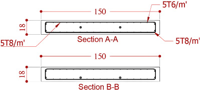
Cross sections A-A and B-B.
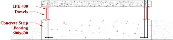
Supporting system.
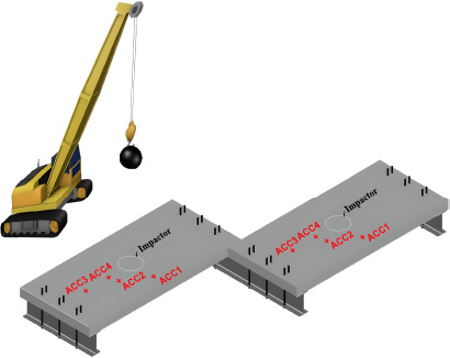
3D sketch of tested slabs showing the supporting system and impactor.
The total energy provided from the free fall was calculated based on the following equation Eq. (3):
 |
(3) |
Where E is the total provided energy for the system in (J), m is the mass of the falling object in (kg), g is the gravitational acceleration and equal to (9.81 m/s2), and h is the height of the falling object (m). In this case, the total provided energy was 47088 J.
2.3. Experimental Testing
The slabs were equipped with accelerometer sensors positioned at specified places on each slab, as depicted in Fig. (8). The placement of the accelerometers was thoroughly selected to cover the slabs' critical zones while avoiding the initial impact zone, where anticipated damage could lead to inaccurate readings. To measure the slabs' reactions during the impact, the accelerometers were connected to a data collecting system. Each sensor could monitor frequencies between 10,000 and 15,000 Hz, a resolution frequency greater than 50 Hz, and loads up to 500 g with a sensitivity of 10 mV/g. The data collecting system facilitated precise measurement of acceleration from which the displacement resulting from the collision was deducted. These readings were subsequently employed to compute the impact force. The resultant damage and cracks from the impact were recorded and analyzed for comparison.
2.4. Numerical Modeling
A realistic prediction of the structural response through numerical analysis requires a rigorous three-dimensional finite element modeling of the different structural components. In the present study, the finite elements code Abaqus was used. The explicit module of this code allows highly non-linear transient dynamic analysis of phenomena like impacts. Abaqus also offers the possibility of managing several interactive entities (the slab and the block in the present case). The analysis can, therefore, introduce the impact in a way similar to that of the experiment, managing only the impact characteristic. To predict the real structural response through numerical analysis, a three-dimensional element finite element model was built incorporating the different structural components involved in the experimental scheme. The volumetric finite element (FE) program “ABAQUS” was used to perform nonlinear analysis of the post-tensioned slabs. The explicit module in the FE software is adequate for the analysis of non-linear dynamic events such as impacts. ABAQUS also allows the interaction of multiple entities, such as the slab and the impactor, in this experiment. This characteristic allows the replication of the impact conditions similar to the experimental setup.
2.4.1. FE Model
The models were modeled as a replica of the experimentally tested slabs (Fig. 9). They are composed of two main parts: the concrete slab and the sphere impactor, which were modeled using a 3D deformable solid element. Various element types were used. For the concrete and sphere impactor, an eight-node brick element C3D8R with reduced integration was used. The steel reinforcement and post-tensioned cables, a two-node three-dimensional truss element type T3D2 was used. The reinforcement detailing was typical to the experimentally used detailing as shown in Fig. (10). The reinforcement was embedded in the concrete body to maintain full bonding conditions. The steel impactor applies impact loading to the slab in a vertical direction, so only vertical movement of the impactor is released by assigning a gravity force in the software. Rigid support was implemented in the experiment. The behavior induced by this support was resembled by two-line pin supports as boundary conditions. A dynamic explicit analysis method was selected for the case, using a time step that closely aligns with the experimental interaction time.
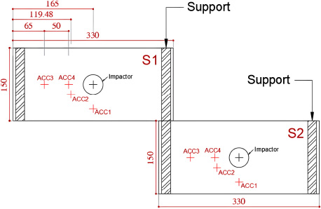
Test setup and accelerometers’ locations.
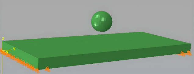
FE model with supports.
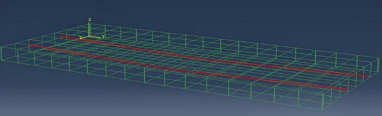
Shear reinforcement and PT tendons.
2.4.2. Material Model
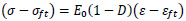
There is a necessity for the defined material behavior under dynamic impact loading shall be realistic to attain an accurate simulation of structural reaction. This entails considering critical processes related to damage from dynamic loading in concrete, such as the decrease in material stiffness due to cracking, the restoration of stiffness when cracks close, and the development of inelastic strains during the damage process. For calibration, Pontiroli, Rouquand and Mazars (PRM) [23] damage model was used. The PRM used one scalar damage variable D, which is the damage indicator due to tension (Dt) and compression (Dc). This variable ranges from 0 to 1, where 0 indicates uncracked material and 1 for macro-cracked material. The one-dimensional expression of the stress-strain relationship is the following Eq. (4):
 |
(4) |
Where, E0 is the modulus of elasticity, σft is the crack closure stress intension and εft is the irreversible strain corresponding to σft.
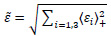
The variation of D is governed by the equivalent strain as Eq. (5):
 |
(5) |
Where
 resembles the positive values of the principal strains. The damage variable D is computed using the damage indicators in tension (Dt) and compression (Dc) in Eq. (6):
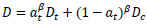 |
(6) |
aβt evolves between 0 and 1 and the actual values depend on ε - εft.
The damage evolution is given by Eq. (7):
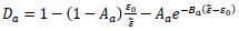 |
(7) |
With a=c,t
σft and εft are considered as material parameter data and calculated based on the Eqs. (8 and 9):
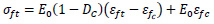 |
(8) |
 |
(9) |
The material parameters of the model were identified from classical data for concrete and rebars, where fc and fs are the ultimate strengths of concrete and steel. Before any damage in compression, εft = εft0 (material parameter), afterwards εft is directly linked to DC. The transition between the two kinds of damage is located at (σft, εft).
The typical stress-strain response produced by this model is shown in Fig. (11).
PRM model of concrete behavior.
Acceleration vs time for S1 and S2 under impact load.
Displacement vs time for S1 and S2 under impact.
The ultimate strengths in compression and tension were determined from the compressive and split tensile testing conducted on cylindrical specimens according to ASTM C496/C496M and C39/C39M, respectively, as shown in Figs. (2 and 3) and from which the modulus of elasticity E0 was deduced. For the specimen without fibers used to cast S1, E0 was found to be 28000 MPa and 29000 MPa for concrete specimens of S1 and S2, respectively. The poison’s ratio used was 0.2. In finite element simulations, the correct estimation of the element's characteristic length (lc) is crucial. The fundamental approach where lc is computed as the cubic root of the element volume was used. The mesh size was considered 30x30x30 mm. A study on the mesh sensitivity is presented in the results section for a detailed explanation of the reason behind considering this mesh element size.
3. RESULTS AND DISCUSSION
3.1. Experimental Results
3.1.1. Acceleration and Displacement
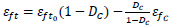
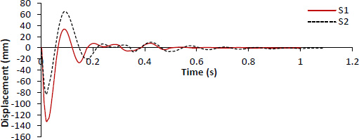
The utilization of the data collecting equipment facilitated the recording of the accelerations and displacements induced in the two slabs due to impact. The results are taken from ACC2, as it is the closest to the center of impact. Despite both slabs having identical concrete compressive strength, the control slab (S1) demonstrated an acceleration of 215g, whereas with the slab with fort-ferro (S2), the maximum measured acceleration reached 244g (Fig. 12). Therefore, S1 exhibited a 12% lower acceleration compared to S2, which was equipped with fibers. In contrast, the data on displacements indicated that S1 had a displacement of 132 mm, which was 38% higher than the displacement seen for S2, measuring 82 mm (Fig. 13). Although S1 exhibited a lower acceleration value in comparison to S2, suggesting a somewhat less dynamic response, it has demonstrated a stiff behavior upon impact and facilitated a more rapid transmission of the impact force. The higher magnitude of acceleration observed in S2 suggests a greater degree of flexibility and ductility in the material's behavior. An additional occurrence was detected through the analysis of the acceleration versus time graph depicted in Fig. (8). Specifically, it was seen that at 0.04 seconds, the response of S1 ceased, whereas S2 continued to exhibit a response to the impact force resulting from the collision. The two slabs have the same moment capacity and thus shall exhibit the same displacement under impact load. However, S1 exhibited greater displacement compared to S2. Upon examination of the two slabs, S1 experienced a collapse, resulting in the cessation of response and acceleration recording, whereas S2 continued to absorb the forces generated by the impact. Forta-Ferro fibers provide post-crack residual strength to concrete, thereby reducing cracking and enhancing overall structural integrity. S2 demonstrated the capacity to efficiently absorb and distribute energy over a prolonged period. S2 demonstrated moderate failure, whereas S1 underwent complete structural failure. The use of fibers has augmented the structural efficacy of the post-tensioned slab through enhancements in its ductility by bridging cracks and preventing their propagation. The presence of fibers contributed to higher residual strength which helped S2 to continue supporting the loads. On the other hand, S1 lost its load-bearing capacity and failed. It is known that fibers in concrete contribute to better energy absorption under impact, which results in a more controlled and gradual deformation. This phenomenon was observed in S2 while S1 underwent sudden brittle failure, which imposed a higher recorded displacement. The results are in accordance with the results Chouw and Wang [24] documented in their study, which demonstrated that concrete specimens without fibers experienced greater damage compared to those reinforced with fibers. Likewise, Harajli et al. [25] emphasized that conventional concrete, lacking fiber reinforcement, exhibits a more brittle failure mode when subjected to impact loading, which also supports the results observed after testing S1 and S2.
3.1.2. Impact Force
The impact force for the two slabs was calculated based on the following Eq. (10):
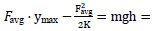 |
(10) |
where “m” is the mass of the impactor = 600 kg; “g” is the acceleration due to gravity; “h” is the height from which the impactor was left to fall freely = 8 m; Favg is the average impact force, and K is the shear stiffness defined as K = GA/L (where A is the critical perimeter multiplied by the thickness, and L is the distance between the support and the impact point and G is the shear modulus). The impact force of S1 was 622 kN, while S2 was 580 kN, as shown in Table 1.
One of the indicators that show the efficiency of the use of fibers is the impact force to maximum displacement (F/D) ratio, as shown in Fig. (14). This ratio resembles the force needed for each slab to generate a unit displacement. The ratios F/D computed were 4.7 and 7.1 for S1 and S2 respectively. The ratio of S2 was 33% larger than S1. This difference indicates that the presence of fibers enhanced the impact resistance of the PT slab and
| Slab | Maximum Acceleration (g) | Maximum Displacement (mm) | Impact Force (kN) |
|---|---|---|---|
| S1 | 215 | 132 | 622 |
| S2 | 244 | 82 | 580 |
energy absorption of concrete. This also explains the robustness of the S2, as it showed minimal damage in comparison to the control slab. The incorporation of Forta-Ferro fibers made the concrete more tough thus more resilient to impact load. Dashti and Nematzadeh [8] demonstrated that the inclusion of Forta-Ferro fibers increases tensile strength and controls crack propagation, thus improving toughness and resilience under dynamic loads.
3.1.3. Crack Pattern
The energy generated caused damage to both slabs. The slabs' cracks and failures post-impact were systematically analyzed. Cracks on the bottom and top faces of the two slabs were highlighted and analyzed to determine the mode of failure, as shown in Fig. (15). Scabbed areas were highlighted. The wide scabbed area of 1.5 m2 in the tension zone indicates that the slab experienced significant tensile stress during the impact, leading to extensive cracking and spalling. In the lack of fibers, the concrete could not resist the high tensile forces effectively, resulting in widespread damage. The dynamic nature of the impact intensified this effect, as concrete is typically more vulnerable to cracking under sudden, high-stress conditions. The scabbed region in the tension zone has been significantly reduced to 0.008 m2. The substantial decrease illustrates the efficacy of fiber reinforcing in mitigating tensile damage. The fibers in S2 effectively absorbed and dissipated impact energy, hence preventing the development of large cracks and minimizing surface damage. The fibers provided post-crack strength, enabling the slab to withstand additional crack propagation under dynamic loading.
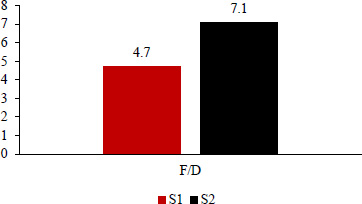
Impact force to maximum displacement bar graph.
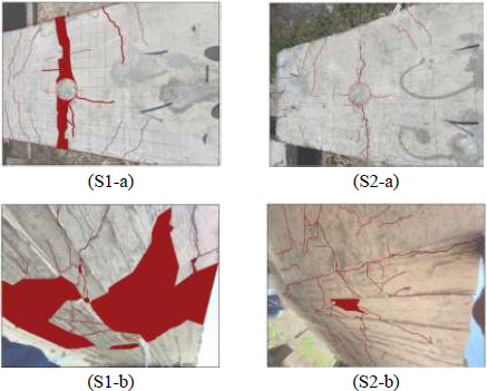
Crack patterns after impact. S1-a and S2-a represent the compression zone of slabs. S1-b and S2-b represent the tension zone of slabs.
The shear strength of slabs S1 and S2 before impact was 605 kN. Table 1 indicates that the impact forces of slabs S1 and S2 were 622 kN and 580 kN, respectively. In comparing shear strength to impact forces, it was observed that S1 exhibited an impact force exceeding the shear strength of the slab, whereas S2 demonstrated an impact force that was lower than the shear strength of the slabs. This is similar to the findings of Dashti et al. [1], which stated that the inclusion of Forta-Ferro fibers at a volume fraction of 0.4% can substantially enhancedirect tensile strength, leading to a reduction in crack propagation and an improvement in the overall ductility of concrete.
3.2. Numerical Results
In this section, the values of the calibrated models are compared to the experimental results to show the ability of this constitutive model to reproduce the real material behavior and structural response under impact.
3.2.1. Mesh Sensitivity
Mesh sensitivity analysis was performed to study the effect of mesh refinement on the numerical simulation results compared to experimental results. The analysis was performed by changing the mesh size and plotting the results for the two numerical models resembling S1 and S2. Four different mesh sizes were considered 20x20x20 mm, 30x30x30 mm, 40x40x40 mm and 60x60x60 mm. Each time the mesh size was changed, a new “job” was created and the results were collected. The computation time was also monitored for full analysis to be completed. The maximum displacements were determined from the contour plot option and the plots showing the maximum displacement with time were produced. The results obtained were compared to the experimental results. Table 2 summarizes the results obtained.
Fig. (16) is a graphical presentation of the mesh sensitivity analysis. The mesh convergence rate for S1 and S2 improves significantly as the mesh is refined. The rates between 60 and 40 were 16.4% and 16.8% for S1 and S2 respectively. These rates decreased between 40 and 30 to 5.6% and 6.3% respectively. The optimal rates were between 30 and 20, where the recorded rates were 2% and 4.8%, respectively. These rates indicate that the displacement values are stabilizing as the mesh size decreases and that further mesh refinement beyond 20 will not significantly change the results. The finest mesh 20 increased the computational time compared to other mesh sizes. For this reason, mesh size 30 mm was considered in this study as it gave efficient results without significant loss in accuracy, as the time factor is essential for further parametric analyses.
| Mesh Size | Numerical Displacement (mm) | |
|---|---|---|
| S1 | S2 | |
| 20 | 138.4 | 75.5 |
| 30 | 135.5 | 72.0 |
| 40 | 128.3 | 67.7 |
| 60 | 110.3 | 58.0 |
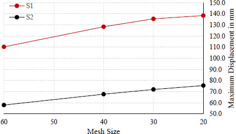
Mesh sensitivity analysis.
3.2.2. Displacement
Figs. (17 and 18) represent the numerical displacements obtained at the corresponding location of ACC2 in the models for S1 and S2. The displacements obtained from the models were equivalent to the displacements obtained in the experimental work. The peak displacements recorded were 135 mm and 72 mm for S1 and S2, respectively. The results show that the numerical model was capable of giving a deformed shape similar to that obtained in reality, with a percentage difference of 2.7% and 12.3% in displacement compared to the experimental values obtained. The results are summarized in Table 3.
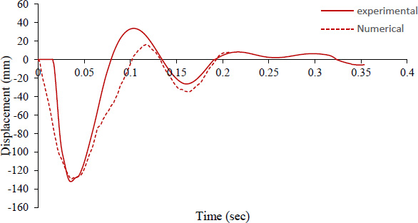
Experimental versus numerical displacement results for S1.
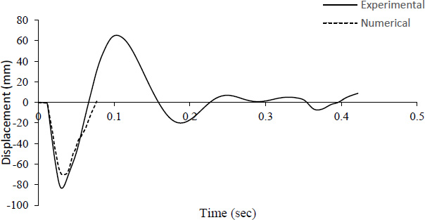
Experimental versus numerical displacement results for S2.
| Slab | Maximum Displacement FE | Maximum Displacement Experimental (mm) | Error |
|---|---|---|---|
| S1 | 135 | 132 | 2.7% |
| S2 | 72 | 82 | 12.3% |
3.2.3. Crack Pattern
The crack patterns under impact were compared between the developed models and the experimental outcomes. The damage profiles on the top and bottom faces were examined and compared to the actual experimental patterns.
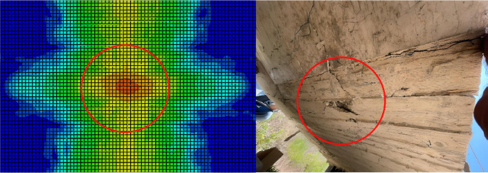
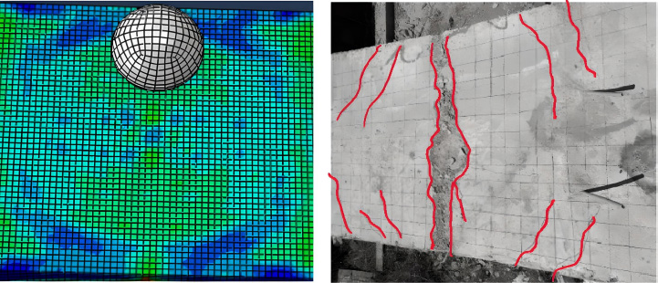
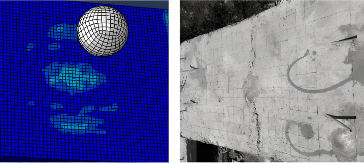
The bottom damage in the models Figs. (19 and 20) were like the experimental. In a similar manner, Figs. (21 and 22) show the top damage in S1 and S2 numerically and experimentally. The models showed an acceptable representation of the damage in compression on the top faces.
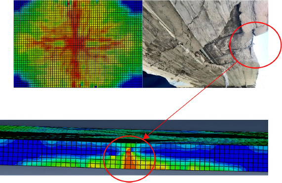
Bottom tension damage in S1.
Bottom concrete damage in S2.
Top damage in S1.
Top damage in S2.
CONCLUSION
This study examined the inclusion of 0.4% forta-ferro fibers by concrete volume in post-tensioned slabs and their effects on the dynamic structural response of these slabs under impact loading from a free-falling body. This study considered two slabs, designated as S1 and S2. The two slabs had identical moment capacity and were cast using the same concrete mix; however, 0.4% by volume of forta-ferro fibers were added to the concrete mix prior to casting S2. S2 could tolerate 12% higher acceleration than S1. S2 showed 38% lower displacement than S1. The computed impact force to displacement ratio of S2 was 33% larger than the ratio of S1. S2 showed minimal damage compared to S1, which totally collapsed. The numerical model was able to reproduce the real behavior of slabs.
Based on the observations and the analysis of the results, the following conclusions were drawn:
- Forta-Ferro fibers in the concrete slab enhance ductility, reduce cracking, offer post-crack residual strength, and facilitate energy absorption. The synergistic benefits enable the fiber-reinforced slab to demonstrate reduced displacement and maintain its structural integrity under impact loads, unlike a slab without fibers. To effectively withstand impact threats, slabs must have significant ductility and resilience to prevent catastrophic, irreparable failures.
- The fibers facilitate regulated cracking, energy absorption, and preservation of structural integrity, together resulting in a more resilient and enduring structural response.
- The fibers seemed to affect the failure mode, encouraging a more ductile reaction under impact loads.
- The incorporation of 0.4% forta-ferro fibers is advantageous for improving the dynamic structural performance of post-tensioned slabs.
- PRM is adequate to represent the damage and structural response in terms of displacement and radial cracking. Mesh refinement is essential for model calibration. Mesh sensitivity analysis allows the selection of the optimum mesh size for accurate simulation.
This study provided promising results regarding the use of Forta-Ferro in post-tensioned slabs under impact loading. The results showed the resilience provided to slabs when Forta-Ferro fibers were added in terms of controlled deflection and cracks and higher impact resistance when compared to slabs with conventional PT reinforcement. For further studies, it is recommended to compare the behavior of post-tensioned slabs with fibers to post-tensioned slabs reinforced with conventional shear reinforcement. It is also worth investigating the response of post-tensioned slabs with forta-ferro under successive impacts and compare with other types of fibers. In addition, comparing the response of PT slabs with fibers to conventional RC slabs having the same moment capacity under the same loading conditions.
AUTHORS’ CONTRIBUTIONS
The study conception and design were carried out by S.C. and Y.T: data collection was conducted by; S.C. and M.D: and the analysis and interpretation of results were performed by; S.C: All authors reviewed the results and approved the final version of the manuscript;.
LIST OF ABBREVIATIONS
| UHPSCC | = Ultra HighPerformance Self-Compacting Concrete |
| CFSTTs | = Concrete-Filled Steel Tube Trusses |
| CDP | = Concrete-Damage-Plasticity |
| FE | = Finite element |
AVAILABILITY OF DATA AND MATERIAL
The data sets used and/or analysed during this study are available from the corresponding author [S.C] upon request.
ACKNOWLEDGEMENTS
Declared none.

