All published articles of this journal are available on ScienceDirect.

Comparative Assessment of Reinforced Concrete Slab Systems for Office Buildings in Kuwait
 iD
iD
Authors Info & Affiliations
Abstract
Introduction/Objective
The selection of a reinforced concrete slab system influences structural efficiency, cost, embodied carbon, and serviceability. Six cast-in-place slab systems were compared for a four-story office building in Kuwait with 6- and 9-meter spans to determine which system provides the best overall performance.
Methods
Twelve CSI ETABS models were developed. Loads were specified in accordance with ASCE 7-16, and reinforced concrete design was in accordance with ACI 318-19. Evaluated parameters included concrete and reinforcement quantities, direct material cost, embodied CO2 emissions, structural weight, vertical natural frequency, and X-direction seismic displacement. An MCDM method was used to rank the alternatives, with deflection, punching shear, and story drift assessed separately.
Results
The flat slab with drop panels (Design 5) achieved the highest ranking at both spans, with MCDM scores of 0.989 and 0.993. This system resulted in the lowest cost, embodied CO2 emissions, structural weight, and X-direction displacement. At a 9-meter span, Design 5 reduced cost and CO2 emissions by 6.4% and 7.3%, respectively, compared to the next-best alternative.
Discussion
The results indicate that maximizing stiffness does not always yield the most efficient structural solution. Targeted strengthening at column zones can enhance performance without incurring the material costs associated with continuous beams.
Conclusion
For similar office buildings in Kuwait, Design 5 provides the optimal balance of economy, sustainability, structural efficiency, and serviceability, pending project-specific verification.
1. INTRODUCTION
1.1. Background and Importance of the Current Research Study
Reinforced concrete floor slabs strongly influence building cost, material consumption, embodied carbon, serviceability, and construction speed. Engineers, therefore, should not treat slab selection as a routine detailing step. Recent studies show that slab geometry, slab thickness, concrete grade, and structural layout affect both economic and environmental performance, and that multicriteria assessment improves early design decisions. For this reason, engineers need slab-selection guidance that moves beyond first cost and compares structural systems through a broader set of decision variables [1-3].
The recent literature also shows that span length is one of the strongest drivers of slab efficiency. Feiri et al., Hafez et al., Paknahad et al., and Almasailam et al. showed that span, slab typology, reinforcement demand, and binder choice materially affect embodied carbon and system feasibility [4-7]. Rady, Jari, Abdulghafour, and Ahmad et al. also showed that span length affects the optimal economic solution and can shift preference from one slab system to another as spans increase [8-10]. These findings confirm that slab-system selection should occur early in the design process, when engineers can still modify span grids and floor typologies without major redesign [4-10].
Environmental comparison studies reinforce the same conclusion. Paik and Na found that flat plate and voided slab systems can reduce construction-phase carbon emissions compared with ordinary reinforced concrete slabs [11], while Wang et al. showed through life-cycle assessment that different concrete floor systems, including precast, composite, and cast-in-situ slabs, can produce different environmental impacts depending on the selected system and uncertainty assumptions [12]. However, these studies did not focus on Kuwait, did not compare the full range of common cast-in-place slab systems used in local office buildings, and did not integrate dynamic and lateral-response measures into a single practical selection framework [11, 12].
Recent design-oriented studies further explain why engineers must consider load-transfer path, span arrangement, stiffness, serviceability, punching shear, material efficiency, and constructability when comparing slab systems. Belizario-Silva et al. evaluated seven cast-in-place reinforced concrete floor systems for a four-story building and showed that the choice of floor system can strongly affect material use, cost, labor intensity, and embodied carbon [13]. Rady and Mahfouz compared flat plates, flat slabs with drop panels, and solid slabs, and showed that concrete grade and column spacing influence the optimal cost of reinforced concrete buildings [14]. Jayaweera et al. emphasized that code-compliant slab-beam optimization must satisfy structural safety, serviceability, and cost-efficiency [15]. Ravasini et al. showed that deflection and cracking remain essential serviceability checks for reinforced concrete flat slabs [16], while research on punching shear confirms that slab-column load transfer and local column-region detailing are critical for flat-slab behavior [17, 18]. These studies support the need to evaluate slab alternatives using structural, serviceability, cost, and environmental indicators, but they do not provide a Kuwait-specific early-stage selection guide for routine office buildings.
Design-oriented system selection and regional sustainability studies also underscore the need for a practical decision framework. Hicazi et al. developed a value-engineering-based decision framework for structural slab selection and showed that slab choice should consider multiple cost and performance criteria rather than a single metric [19]. Studies on seismic response also confirm that stiffness, ductility, damping, and displacement control remain central to structural system assessment [20, 21]. In the Gulf context, Bashir et al. identified cost, organizational, compliance, and sustainable-design barriers that affect the implementation of environmental sustainability in UAE construction project management [22]. The regional case study of a large 3D-printed villa further shows that the Gulf region is actively exploring innovative construction approaches [23]. Gauch et al. also showed that early-stage design decisions, including column grid, frame type, and floor/decking choice, strongly affect cost and embodied carbon in multi-storey buildings [24]. Together, these studies justify a practical Kuwait-based framework that helps engineers select slab systems that remain economical, buildable, sustainable, and structurally reliable under local conditions [19-24].
Against this background, this study compares six cast-in-place reinforced concrete slab systems for an office building in Kuwait and evaluates them at span lengths of 6 and 9 meters. The study examines cost, concrete quantity, reinforcement quantity, structural weight, CO2 emissions, vertical natural frequency, and horizontal movement under earthquake loading. This integrated scope defines the work’s novelty and addresses a practical gap in the field: engineers in Kuwait need clear, evidence-based guidance on slab selection during preliminary design, rather than after key geometric decisions have already been made.
1.2. Literature Review
1.2.1. Slab System Selection and Decision-making Frameworks
Researchers increasingly treat slab-system selection as a multicriteria design problem. Salomão and Pinheiro showed that engineers should evaluate productivity, waste generation, architectural flexibility, and comfort together with structural performance and cost [1]. Eleftheriadis et al. linked finite-element analysis and building information modeling with design optimization and showed that slab thickness and structural layout strongly shape both cost and CO2 emissions [2]. Rady extended this logic by translating optimization results into practical guidance for different building functions and span ranges [8]. These studies show that rational slab selection requires a structured framework rather than a single-variable cost check [1, 2, 8].
1.2.2. Span Length, Material Demand, Cost, and Embodied Carbon
The strongest recurring theme in the literature is the effect of span length. Jayasinghe et al. showed that reducing slab thickness within allowable limits and using lower concrete grades can lower embodied carbon in flat slabs [3]. Feiri et al. and Hafez et al. showed that slab design, span width, reinforcement optimization, and binder choice materially affect the decarbonization potential of reinforced concrete buildings [4, 5]. Paknahad et al. compared several reinforced concrete slab systems for office-type applications and showed that the preferred system varies with span length [6]. Almasailam et al. further showed that longer spans can increase total carbon footprint even when higher-strength concrete reduces material volume [7].
Cost studies report the same trend. Rady found that optimal flat-slab solutions depend on live load, concrete strength, and span [8]. Jari and Abdulghafour quantified a strong span-cost relationship for flat slabs and showed that material unit cost rises markedly as span increases [9]. Ahmad et al. showed that the most economical slab type varies with span length, with flat slabs more attractive at shorter spans and post-tensioned slabs becoming more competitive at longer spans [10]. Environmental studies also show that the choice of floor system affects both construction-phase emissions and life-cycle impacts. Paik and Na compared ordinary reinforced concrete slabs, flat plates, and voided slabs [11], while Wang et al. compared various concrete floor slab systems and showed that environmental performance depends on the selected floor system and the assumptions used in life-cycle assessment [12].
1.2.3. Structural Response, Stiffness, and Serviceability
A practical slab-selection study must also address structural response and serviceability. Belizario-Silva et al. showed that different cast-in-place reinforced concrete floor systems can produce large differences in material use, cost, labor intensity, and embodied carbon, confirming that floor-system layout is a design-level decision rather than only a material-quantity issue [13]. Rady and Mahfouz further showed that column spacing and concrete grade affect the optimal cost of reinforced concrete buildings with flat plates, flat slabs with drop panels, and solid slabs [14]. Jayaweera et al. emphasized that code-compliant slab-beam optimization must consider structural safety, serviceability, and cost-efficiency simultaneously [15]. Ravasini et al. showed that deflection and cracking verification are essential serviceability-limit-state checks for reinforced concrete flat slabs [16]. Abbaszadeh et al. and Grabski and Ambroziak also confirmed that slab strengthening, column-region behavior, and punching shear influence slab performance and detailing requirements [17, 18]. At the system level, research studies showed that increased damping and improved stiffness can modify ductility and displacement response in framed systems [20, 21]. These findings justify the inclusion of vibration, horizontal displacement, deflection, punching shear, and serviceability-related variables when engineers compare slab systems for real buildings [13-18, 20, 21].
1.2.4. Regional Context and Study Relevance
The Gulf region still lacks sufficient local studies that translate structural optimization into early-stage design guidance for routine office buildings. Hicazi et al. developed a value-engineering and multi-criteria decision-making framework for structural slab selection, showing that slab-system choice should be based on combined cost and performance considerations [19]. Bashir et al. documented barriers to implementing environmental sustainability in UAE construction project management, including economic, organizational, compliance, and sustainable-design implementation barriers [22]. The regional case study of a large 3D-printed villa further shows that the Gulf region is moving toward more innovative and sustainability-focused construction practices [23]. Gauch et al. showed that early-stage design decisions, such as the column grid, frame type, and floor/decking choice, can substantially affect carbon and cost outcomes in multi-storey buildings [24]. Collectively, these studies support the need for locally grounded, performance-based guidance for slab-system selection in Kuwait, where engineers must balance cost, structural reliability, serviceability, constructability, and sustainability during preliminary design [19, 22-24].
1.2.5. Research Gap and Contribution of the Present Study
Previous research offers valuable insights into slab-system optimization, cost reduction, embodied-carbon assessment, and structural response. However, three significant gaps persist. First, most studies focus on optimizing a single slab family or comparing only a limited range of alternatives, despite the need for engineers to select from several conventional cast-in-place reinforced concrete slab systems during preliminary design [3-12]. Second, existing literature typically prioritizes one dominant criterion, such as material cost, embodied carbon, span efficiency, serviceability, or a specific structural-response parameter, rather than integrating economic, environmental, dynamic, serviceability, and seismic-response indicators within a unified decision framework [1, 2, 8, 11-16, 18-21, 24]. Third, Kuwait-specific decision guidance for routine office buildings remains limited, even though regional and early-stage design studies indicate that local cost conditions, constructability, sustainability constraints, span/grid selection, and structural-performance requirements can significantly affect system selection [19, 22-24].
This study addresses these gaps by systematically comparing six common cast-in-place reinforced concrete slab systems for a four-story office building in Kuwait, considering two practical span lengths: 6 meters and 9 meters. The evaluation encompasses concrete quantity, reinforcement quantity, direct material cost, embodied CO2 emissions, structural weight, vertical natural frequency, and seismic horizontal movement, all assessed within a consistent ETABS-based framework. The primary contribution of this research is the integration of six locally relevant slab alternatives, two practical span scenarios, and multiple economic, environmental, dynamic, and seismic-response indicators into a comprehensive early-stage selection guide for office buildings in Kuwait.
2. METHODS
2.1. Research Design and Case Study Definition
This study used a comparative parametric approach to evaluate the structural, economic, and environmental performance of reinforced concrete slab systems for office buildings in Kuwait. The study selected a four-story office building as the reference case because office buildings require repetitive floor systems, moderate live loads, flexible interior planning, and reliable serviceability performance. These characteristics make office buildings suitable for comparing slab alternatives under practical design conditions.
The study adopted a square building plan of 36 × 36 meters and investigated two span layouts, 6 and 9 meters. It kept the building use, overall geometry, material properties, load definitions, and design assumptions constant and varied only the slab system and span length. This procedure isolated the effect of slab typology on material demand, direct material cost, embodied CO2 emissions, structural weight, vibration response, and lateral movement.
The study investigated six slab alternatives:
Design 1: one-way solid slab, which is shown in Fig. (1a and b).
Design 2: two-way solid slab with beams is shown in Fig. (1c and d)
Design 3: flat slab with edge beams and drop panels is shown in Fig. (1e and f)
Design 4: flat slab with edge beams is shown in Fig. (1g and h)
Design 5: flat slab with drop panels is shown in Fig. (1i and j)
Design 6: flat plate is shown in Fig. (1k and l)

Finite Element Model for all design options using CSI ETABS Software with plan view on the left and 3D view on the right. (a) Design 1 with a 6m span length, (b) Design 1 with a 9m span length, (c) Design 2 with a 6m span length, (d) Design 2 with a 9m span length, (e) Design 3 with a 6m span length, (f) Design 3 with a 9m span length, (g) Design 4 with a 6m span length, (h) Design 4 with a 9m span length, (i) Design 5 with a 6m span length, (j) Design 5 with a 9m span length, (k) Design 6 with a 6m span length, and (l) Design 6 with a 9m span length.
The study therefore developed 12 analytical models in total, with six slab systems assessed at each span.
2.2. Materials and Design Basis
The study designed all alternatives as normal-weight reinforced concrete systems. It adopted a concrete compressive strength, , of 30 MPa and a steel yield strength,
, of 420 MPa. The unit weight of concrete was 24 kN/m3. The design used a clear concrete cover of 50 mm at the top and bottom of the slab elements and adopted an initial reinforcing bar diameter of 20 mm during preliminary sizing.
The study followed ASCE 7-16 for load definition and load combinations [25] and used ACI 318-19 for reinforced concrete design. It applied the same material properties and code basis to all 12 models to maintain a consistent comparison.
2.3. Loading Criteria
The study applied dead, live, wind, and seismic loads to all models in CSI ETABS. Table 1 summarizes the adopted loading criteria and key assumptions.
The Equivalent Lateral Force (ELF) method was selected for the seismic comparison because the reference building is a low-rise four-story office building with a regular square plan and consistent diaphragm action at each floor level. Based on the seismic parameters adopted in Table 1, SDS = 0.0928, SD1 = 0.0752, and Ie = 1.0, the governing seismic design category is controlled by SD1 and corresponds to Seismic Design Category B according to ASCE 7-16 Tables 11.6-1 and 11.6-2 [25]. For this category, ASCE 7-16 permits the ELF procedure through the analysis-procedure selection requirements in ASCE7-16 Section 12.6 and Table 12.6-1, with the equivalent lateral force calculation performed in accordance with ASCE7-16 Section 12.8 [25]. Therefore, the ELF method was considered appropriate for the comparative early-stage assessment performed in this study. Response-spectrum analysis was not adopted because the objective was not to perform detailed final seismic design of a tall, irregular, or high-seismic-demand structure, but to compare slab alternatives on a single consistent code-permitted lateral-load basis.
Table 1 shows that the study used one consistent loading framework for all slab alternatives. This approach ensured that differences in the results came from slab-system behavior and span length rather than from changes in the loading assumptions.
| Load Category | Adopted Values |
|---|---|
| Dead load | Ceiling and services = 0.35 kN/m2; superimposed dead load = 3.00 kN/m2; partition load = 0.96 kN/m2; slab self-weight = calculated automatically by ETABS from assigned section properties [25]. |
| Live load | Office live load = 2.40 kN/m2 [25]. |
| Wind loading | Basic wind speed = 38.88 m/s (140 km/h) [26]; exposure category = B [27]; windward pressure coefficient (Cpw) = 0.8; leeward pressure coefficient (Cpl) = 0.5; velocity pressure coefficient (Kz) = 1.0; topographic factor (Kzt) = 1.0; ground elevation factor (Ke) = 1.0; gust effect factor (G) = 0.85; directionality factor (Kd) = 0.85; accidental wind eccentricity = 15%. |
| Seismic loading | Equivalent lateral load method applied in the X and Y directions; accidental eccentricity = 5%; (Ss = 0.087); (S1 = 0.047); (TL = 8.0) s; site class = D; (Fa = 1.6); (Fv = 2.4); (SDS = 0.0928); (SD1 = 0.0752); response modification factor (R = 4.5); system overstrength factor (Ω = 2.5); deflection amplification factor (Cd = 4.0); importance factor (Ie = 1.0). |
2.4. Load Combinations
The study used strength load combinations in accordance with ASCE 7-16 [25]. Table 2 lists the governing combinations used in the analysis and design.
| No. | Load Combination |
|---|---|
| 1 | (1.4D) |
| 2 | (1.2D + 1.6L) |
| 3 | (1.2D + 1.0L + 1.0W) |
| 4 | (0.9D + 1.0W) |
| 5 | (1.2D + 1.0L + 1.0E) |
| 6 | (0.9D + 1.0E) |
2.5. Finite Element Modeling and Optimization Procedure
The study developed all structural models in CSI ETABS. It modeled slabs and drop panels as shell elements, beams and columns as frame elements, and walls as wall elements. It assigned diaphragm action at each floor level to transfer lateral loads to the vertical resisting system. The finite element models for all design options are shown in Fig. (1), with the element color designation listed in Table 3.
| Section Types | Color |
|---|---|
| Slabs | Green |
| Beams | Yellow |
| Columns | Blue |
| Walls | Red |
| Drop Panels | Black Edges |
The study followed the same modeling sequence for all 12 cases. First, it defined the building geometry, slab layout, material properties, and preliminary member dimensions. Second, it applied the gravity, wind, and seismic loads summarized in Table 1 and combined them as shown in Table 2. Third, it performed structural analysis and design checks in ETABS in accordance with the ASCE 7-16 loading requirements and the ACI 318-19 reinforced concrete design provisions [25, 26]. The term “optimized” in this study refers to an iterative code-based sizing process rather than an automated mathematical optimization algorithm. After each analysis run, slab, beam, column, wall, and drop-panel dimensions were revised until the models satisfied the adopted strength and serviceability criteria.
The final design acceptance criteria were based on ACI 318-19 strength and serviceability requirements [26]. For strength, the governing ETABS demand-to-capacity ratio, Ru/øRn was required to remain below 1.0, confirming that the factored demand did not exceed the design strength. To avoid uneconomical oversizing, the final member dimensions were selected to achieve a utilization ratio generally above 0.80 and below 1.0 where practical. Strength checks were applied according to the relevant ACI 318-19 member provisions for one-way slabs, two-way slabs, beams, columns, and walls, including Sections 7.4–7.5, 8.4–8.5, 9.4–9.5, 10.4–10.5, and 11.4–11.5, respectively [26]. For serviceability, the long-term deflection was checked under service-level gravity loads in accordance with ACI 318-19 Chapter 24, Section 24.2, and Table 24.2.2. The adopted limit was ΔLT ≤ L/240, where ΔLT is the long-term deflection and L is the span length [26].
After the final accepted ETABS models were obtained, the study extracted material quantities, modal properties, structural weight, and lateral displacement. The alternatives were then compared based on direct material cost, embodied CO2 emissions, structural weight, vertical natural frequency, and horizontal movement.
2.6. Cost Estimation
The study estimated direct material cost from the final quantities of concrete and reinforcing steel. It used Eq. (1):

where Vc is the total concrete volume in m3, Ws is the total reinforcing-steel weight in tons, Xc is the concrete unit price in KD/m3, and Xs is the reinforcing-steel unit price in KD/ton.
The study adopted a concrete unit price of 23 KD/m3 and a reinforcing-steel unit price of 189 KD/ton [28, 29]. The cost model included only direct material cost because concrete and reinforcing steel were the main variables that changed among the slab alternatives.
2.7. CO2 Emissions Estimation
The study estimated embodied CO2 emissions from the quantities of concrete and reinforcing steel by using Eq. (2):

where Vc is the total concrete volume in m3, Ws is the total reinforcing-steel weight in kg, ec is the CO2 emission factor of concrete in kg-CO2/m3, and es is the CO2 emission factor of reinforcing steel in kg-CO2/kg.
The study adopted a concrete emission factor of 383.77 kg-CO2/m3 and a reinforcing-steel emission factor of 3.84 kg-CO2/kg [30]. This estimate represented material-related embodied emissions only.
2.8. Performance Indicators
The study compared the 12 structural models using the following performance indicators:
(1) total concrete quantity,
(2) total reinforcement quantity,
(3) direct material cost,
(4) embodied CO2 emissions,
(5) total structural weight,
(6) first vertical natural frequency, and
(7) peak horizontal movement under seismic loading.
These indicators enabled the study to evaluate each slab system from structural, economic, and environmental perspectives within a single framework.
In addition to the main comparative indicators, supplementary strength and serviceability checks were reviewed to address deflection, punching shear, story drift, and serviceability requirements. These checks were treated as code-compliance verification measures rather than primary ranking criteria. The detailed results are provided in Appendix A. Deflection was not added as a separate weighted MCDM criterion because it is stiffness-dependent and therefore related to the vertical natural frequency already used in the main comparison. However, long-term deflection was still checked independently against the ACI 318-19 serviceability limit of L/240. Punching shear ratios and story drift checks were also reviewed to confirm that the preferred slab system satisfied the relevant strength and lateral-serviceability requirements.
2.9. Scope of the Method
This method provides a practical basis for selecting early-stage slabs for office buildings in Kuwait. However, the cost model includes only direct material costs, and the environmental model includes only embodied emissions from concrete and reinforcing steel. Even with these limits, the method remains suitable for identifying the relative efficiency of common cast-in-place slab systems under consistent local assumptions.
The seismic comparison was limited to the ASCE 7-16 Equivalent Lateral Force method; therefore, response-spectrum or response-history analysis should be considered in future work for taller, irregular, or higher-seismic-risk buildings.
3. RESULTS
3.1. Optimized Structural Dimensions for the Slab Alternatives
The optimized dimensions show that the 9-meter span required larger structural elements than the 6-meter span in all six slab systems. For the 6-meter cases, slab thickness ranged from 230 mm to 280 mm, while beam depth ranged from 350 mm to 400 mm where beams were present. For the 9-meter cases, slab thickness increased to 320-400 mm, and beam depth increased to 500-700 mm. Column dimensions also increased from 350 × 350 mm to 400 × 400 mm in the 6-meter span cases and from 550 × 550 mm to 600 × 600 mm in the 9-meter span cases. These changes confirm that increasing the span imposed higher structural demands on all slab alternatives, as shown in Table 4 and Table 5.
| Design | Slab Thickness (mm) | Beam Depth (mm) | Beam Width (mm) | Drop Panel Thickness (mm) | Column Depth (mm) | Column Width (mm) | Wall Thickness (mm) |
|---|---|---|---|---|---|---|---|
| Design 1 | 250 | 350 | 350 | - | 350 | 350 | 200 |
| Design 2 | 230 | 400 | 350 | - | 350 | 350 | 200 |
| Design 3 | 240 | 400 | 400 | 300 | 400 | 400 | 200 |
| Design 4 | 270 | 400 | 400 | - | 400 | 400 | 200 |
| Design 5 | 240 | - | - | 300 | 350 | 350 | 200 |
| Design 6 | 280 | - | - | - | 400 | 400 | 200 |
| Design | Slab Thickness (mm) | Beam Depth (mm) | Beam Width (mm) | Drop Panel Thickness (mm) | Column Depth (mm) | Column Width (mm) | Wall Thickness (mm) |
|---|---|---|---|---|---|---|---|
| Design 1 | 350 | 550 | 500 | - | 550 | 550 | 200 |
| Design 2 | 320 | 500 | 550 | - | 550 | 550 | 200 |
| Design 3 | 350 | 650 | 550 | 550 | 550 | 550 | 200 |
| Design 4 | 400 | 700 | 600 | - | 600 | 600 | 200 |
| Design 5 | 350 | - | - | 600 | 550 | 550 | 200 |
| Design 6 | 400 | - | - | - | 600 | 600 | 200 |
3.2. Comparative Performance of the Optimized Slab Systems
Table 6 and Table 7 summarize the main quantitative results for the six slab systems. Fig. 1 to Fig. 5 show the same trends graphically.
| Design | Cost, 6 Meters (KD) | Cost, 9 Meters (KD) | CO2 Emissions, 6 Meters (kg) | CO2 Emissions, 9 Meters (kg) | Structural Weight, 6 Meters (kN) | Structural Weight, 9 Meters (kN) |
|---|---|---|---|---|---|---|
| Design 1 | 46,217.75 | 74,626.40 | 811,498 | 1,289,091 | 38,100.5 | 51,885.2 |
| Design 2 | 45,465.40 | 75,431.43 | 798,633 | 1,308,269 | 39,049.6 | 52,352.3 |
| Design 3 | 44,270.04 | 69,820.19 | 776,665 | 1,206,665 | 37,560.8 | 53,532.1 |
| Design 4 | 47,829.89 | 79,906.71 | 834,716 | 1,373,617 | 40,809.5 | 59,805.0 |
| Design 5 | 44,135.90 | 65,360.11 | 773,127 | 1,118,682 | 35,323.1 | 50,957.3 |
| Design 6 | 47,534.50 | 78,232.86 | 825,339 | 1,340,172 | 39,997.2 | 54,386.0 |
| Design | Vertical Natural Frequency, 6 Meters (Hz) | Vertical Natural Frequency, 9 Meters (Hz) | Horizontal Movement in X Direction, 6 Meters (mm) | Horizontal Movement in X Direction, 9 Meters (mm) |
|---|---|---|---|---|
| Design 1 | 4.64 | 3.33 | 6.58 | 7.09 |
| Design 2 | 5.02 | 3.51 | 6.54 | 7.12 |
| Design 3 | 4.94 | 3.60 | 5.29 | 6.63 |
| Design 4 | 5.18 | 3.98 | 5.53 | 6.77 |
| Design 5 | 4.59 | 3.69 | 5.28 | 6.39 |
| Design 6 | 5.15 | 3.61 | 5.65 | 7.36 |
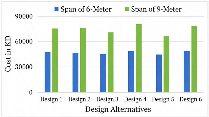
Cost comparison of 6m and 9m slab designs.
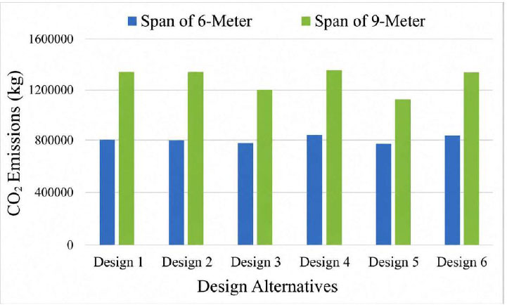
CO2 emissions comparison of 6m and 9m slab designs.
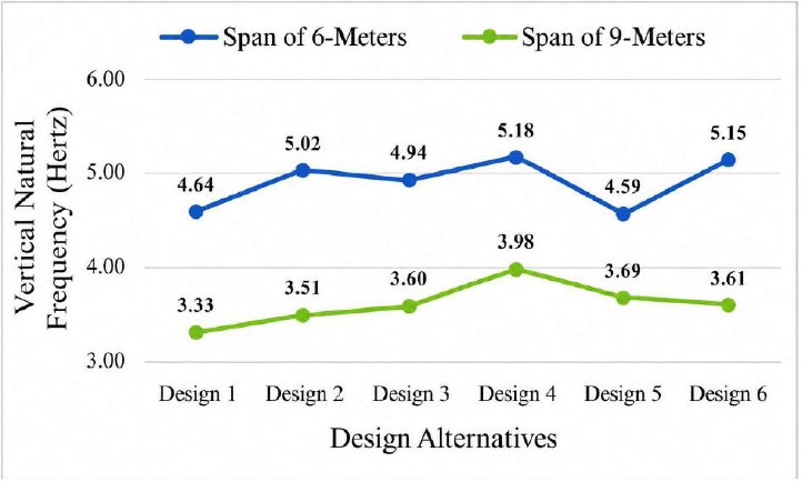
Vertical natural frequency for 6m and 9m slab designs.
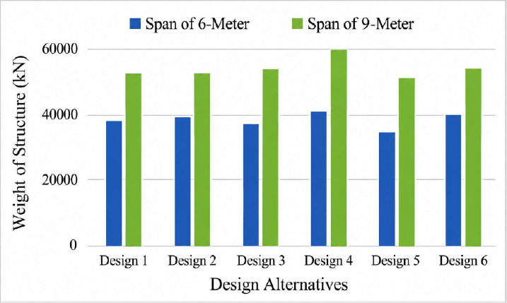
Weight of structure comparison of 6m and 9m slab designs.
3.2.1. Cost Analysis
Table 6 and (Fig. 2) show that the total material cost increased in every slab system when the span increased from 6 to 9 meters. Design 5 produced the lowest cost at both spans, with KD 44,135.90 for the 6-meter span and KD 65,360.11 for the 9-meter span. Design 3 ranked second, with KD 44,270.04 and KD 69,820.19, respectively. Design 4 incurred the highest cost for both spans, at KD 47,829.89 for the 6-meter span and KD 79,906.71 for the 9-meter span. Design 6 also showed a strong span effect, with its cost increasing from KD 47,534.50 to KD 78,232.86, a 64.58% increase, as shown in Table 6 and (Fig. 2).
3.2.2. CO2 Emissions Analysis
Table 6 and Fig. 3 show that CO2 emissions followed the same pattern as cost. Design 5 generated the lowest emissions at both spans, with 773,127 kg at 6 meters and 1,118,682 kg at 9 meters. Design 3 again ranked second, with 776,665 kg and 1,206,665 kg, respectively. Design 4 generated the highest emissions, with 834,716 kg for the 6-meter span and 1,373,617 kg for the 9-meter span. Design 6 increased from 825,339 kg to 1,340,172 kg, representing an increase of about 62.38%, as shown in Table 6 and (Fig. 3). These results confirm that longer spans required greater quantities of concrete and reinforcement, thereby increasing embodied CO2 emissions.
3.2.3. Vertical Natural Frequency Analysis
Table 7 and Fig. (4) show that the vertical natural frequency decreased for all six slab systems as the span increased from 6 to 9meters. For the 6-meter span, the frequencies ranged from 4.59 Hz in Design 5 to 5.18 Hz in Design 4. For the 9-meter span, the frequencies ranged from 3.33 Hz in Design 1 to 3.98 Hz in Design 4. Design 4 therefore produced the stiffest floor response at both spans. Design 6 dropped from 5.15 Hz at 6 meters to 3.61 Hz at 9 meters, which represents a reduction of about 29.99%, as shown in Table 7 and Fig. 4. This trend confirms that the longer span reduced floor stiffness and increased vibration sensitivity.
3.2.4. Structural Weight Analysis
Table 6 and Fig. (5) show that structural weight increased across all six systems as the span increased from 6 to 9 meters. Design 5 had the lowest structural weight at both spans, with 35,323.1 kN at 6 meters and 50,957.3 kN at 9 meters. Design 4 had the highest structural weight, with 40,809.5 kN and 59,805.0 kN, respectively. Design 6 increased from 39,997.2 kN to 54,386.0 kN, representing approximately a 36.0% increase, as shown in Table 6 and Fig. 5. These results indicate that longer spans increased the total dead load and, therefore, overall structural demand.
3.2.5. Horizontal Movement in the X Direction
Table 7 and Fig. (6) show that the X-direction horizontal movement increased in all six designs when the span increased from 6 to 9 meters. Design 5 achieved the lowest displacement at both spans, with 5.28 mm at 6 meters and 6.39 mm at 9 meters. At the 6-meter span, Design 1 produced the highest X-direction displacement, at 6.58 mm. At the 9-meter span, Design 6 produced the highest X-direction displacement, with 7.36 mm. Design 6 also showed the largest span sensitivity, with its X-direction displacement increasing by about 30.17% from 5.65 mm to 7.36 mm, as shown in Table 7 and Fig. 6. These findings indicate that increasing span length reduced lateral stiffness and increased seismic movement.
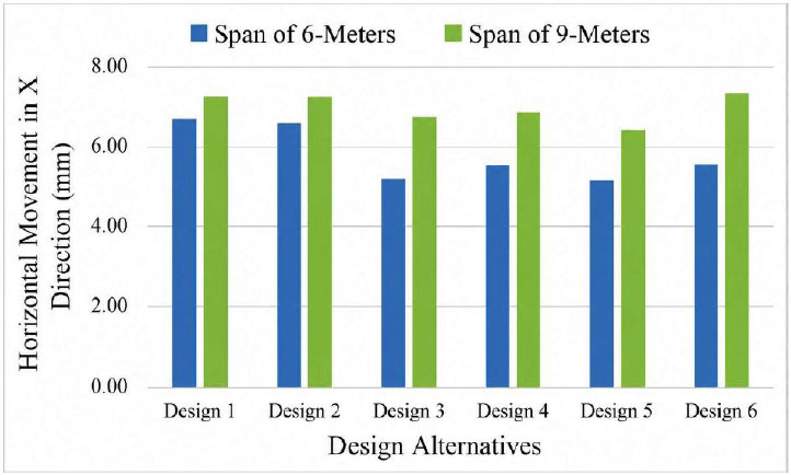
Horizontal movement in X direction comparison of 6m and 9m slab designs.
3.3. Overall Comparison of the Slab Systems
The integrated comparison in Table 6, Table 7, and Fig. 2 to Fig. 6 shows that Design 5 provided the best overall balance among cost, CO2 emissions, structural weight, and X-direction horizontal movement at both span lengths. Design 3 provided the next-best overall balance, especially at the 9-meter span, where it combined the second-lowest cost and CO2 emissions with moderate vibration and lateral-response performance. Design 4 produced the highest vertical natural frequency and therefore the stiffest floor behavior, but it also produced the highest cost, the highest CO2 emissions, and the greatest structural weight. These results show that no single slab system dominated all metrics, but Design 5 consistently delivered the most efficient overall performance.
4. DISCUSSION
4.1. Influence of Span Length on Structural Efficiency
The results in Tables 4 to 7 and Fig. 2 to Fig. 6 show that span length was the dominant factor in slab-system performance. When the span increased from 6 to 9 meters, the optimized member sizes increased for all six alternatives, as shown in Tables 4 and 5. This change increased the concrete and reinforcement demand and directly increased cost, CO2 emissions, and structural weight, as shown in Table 6 and Fig. 2, Fig. 3, and Fig. 5. At the same time, the longer span reduced floor stiffness and increased lateral flexibility, which lowered the vertical natural frequency and increased the X-direction horizontal movement, as shown in Table 7, Fig. 4, and Fig. 6.
4.2. Multi-criteria Ranking and Justification of Design 5
Design 5, which used a flat slab with drop panels, achieved the best combined performance because it placed additional material only where punching-shear demand was highest while avoiding the continuous beam volume required in Designs 2, 3, and 4. This arrangement improved material efficiency and reduced the total demand for concrete and reinforcement. As a result, Design 5 produced the lowest cost, the lowest CO2 emissions, the lowest structural weight, and the lowest X-direction displacement at both spans, as shown in Table 6, Table 7, Fig. 2, Fig. 3, Fig. 5, and Fig. 6. Although Design 5 did not produce the highest vertical natural frequency, it maintained competitive vibration performance and achieved the strongest overall balance among the evaluated criteria.
To formally substantiate the selection of Design 5, a weighted-sum multi-criteria decision-making method was added. Multi-criteria assessment is suitable for slab-system selection because previous studies have shown that rational slab selection should consider economic, environmental, and structural performance indicators together rather than relying on a single parameter [1, 2, 8]. The adopted MCDM criteria, preference direction, and weighting factors are summarized in Table 8. The selected criteria were direct material cost, embodied CO2 emissions, structural weight, X-direction horizontal movement, and vertical natural frequency. Higher weights were assigned to cost and CO2 emissions because economy and sustainability are the main practical drivers for slab-system selection in Kuwait. Structural weight was also assigned high weight because it reflects material efficiency and influences gravity and seismic demands. X-direction horizontal movement and vertical natural frequency were included to represent lateral and dynamic performance.
| Criterion | Preference Direction | Weight |
|---|---|---|
| Direct material cost | Lower is better | 30% |
| Embodied CO2 emissions | Lower is better | 25% |
| Structural weight | Lower is better | 20% |
| X-direction horizontal movement | Lower is better | 15% |
| Vertical natural frequency | Higher is better | 10% |
| Total | — | 100% |
The MCDM analysis used the quantitative indicators reported in Table 6 and Table 7: direct material cost, embodied CO2 emissions, structural weight, vertical natural frequency, and X-direction horizontal movement. The adopted weights were 30% for cost, 25% for CO2 emissions, 20% for structural weight, 15% for X-direction horizontal movement, and 10% for vertical natural frequency. Higher weights were assigned to cost and CO2 emissions because the study focuses on economical and sustainable slab selection for office buildings in Kuwait. Structural weight was also given high weight because it reflects material efficiency and influences gravity and seismic demands. Horizontal movement and vertical natural frequency were included to represent lateral and dynamic performance.
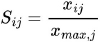
Because the criteria have different units, the values were normalized before weighting. For cost-type criteria, where lower values are preferred, the normalized score was calculated using Eq. (3):

For the benefit criterion, vertical natural frequency, where higher values are preferred, the normalized score was calculated using Eq. (4):
The total MCDM score for each design was then calculated using Eq. (5):

where Sij is the normalized score of design i for criterion j, xij is the original value, xmin,j is the minimum value among the alternatives for cost-type criteria, xmax,j is the maximum value for the benefit criterion, and wj is the criterion weight.
The weighted-sum MCDM scores and final ranking are presented in Table 9.
| Design | 6 Meters MCDM Score | 6 Meters Rank | 9 Meters MCDM Score | 9 Meters Rank | Average Score | Overall Rank |
|---|---|---|---|---|---|---|
| Design 1 | 0.920 | 6 | 0.895 | 3 | 0.908 | 4 |
| Design 2 | 0.932 | 3 | 0.891 | 4 | 0.912 | 3 |
| Design 3 | 0.981 | 2 | 0.938 | 2 | 0.960 | 2 |
| Design 4 | 0.925 | 5 | 0.861 | 6 | 0.893 | 6 |
| Design 5 | 0.989 | 1 | 0.993 | 1 | 0.991 | 1 |
| Design 6 | 0.929 | 4 | 0.868 | 5 | 0.898 | 5 |
For example, for Design 5 at the 6-meter span, the normalized scores for cost, CO2 emissions, structural weight, and X-direction horizontal movement were equal to 1.0 because Design 5 achieved the lowest values among all alternatives for these criteria. Its normalized vertical-frequency score was 4.59/5.18 = 0.886 because Design 4 had the highest frequency at 6 meters. Therefore, the weighted MCDM score for Design 5 was 0.30 (1.0)+0.25(1.0)+0.20(1.0)+0.15(1.0)+0.10(0.886)=0.989.
The ranking confirms that Design 5 achieved the highest MCDM score at both span lengths, with 0.989 for the 6-meter span and 0.993 for the 9-meter span. It also achieved the highest average score, 0.991, across the two span cases. This result confirms that Design 5 is not preferred based on a single isolated result, but because it consistently delivers the best combined performance across the economic, environmental, material-efficiency, dynamic, and seismic-response criteria. Design 3 ranked second overall and may be considered a suitable secondary option, especially where a framed slab system is preferred. However, despite having the highest vertical natural frequency, Design 4 ranked last overall because its stiffness advantage was offset by the highest cost, CO2 emissions, and structural weight.
4.3. Trade-off Between Stiffness and Material Efficiency
The comparison indicates that slab-system selection should not rely solely on stiffness. While a stiffer floor system can enhance vibration response and reduce serviceability sensitivity, it often necessitates larger member sizes, increased concrete volume, additional reinforcement, and higher self-weight. This results in a direct trade-off between structural robustness and material efficiency. Consequently, the optimal slab system is not always the one with the highest vertical natural frequency, but rather the one that achieves sufficient stiffness with minimal material, cost, and carbon impacts.
Design 4 exemplifies this trade-off. The edge-beam configuration increases floor stiffness and improves dynamic behavior, which is advantageous when vibration control or lateral rigidity is a primary design concern. However, these benefits are achieved at the expense of a heavier and more material-intensive system. For typical office buildings, where vibration and drift demands are within acceptable limits, the additional stiffness may not justify the increased cost, embodied CO2, and structural weight. Overemphasizing stiffness in such scenarios can result in a conservative yet less sustainable design.
Design 6 demonstrates a different limitation. The flat-plate system offers the cleanest soffit and maximizes architectural and services flexibility by eliminating beams and drop panels. This is particularly valuable in office projects where ceiling coordination, mechanical services integration, and construction simplicity are priorities. However, beam-free systems are more sensitive to longer spans, as the slab must resist flexure and punching shear with fewer localized stiffness enhancements. Supplementary checks in Appendix A confirm that punching shear becomes increasingly critical in longer-span flat-plate systems, necessitating additional shear reinforcement. Therefore, while flat plates are advantageous for architectural flexibility, their application in longer spans requires thorough evaluation of punching shear, deflection, and vibration performance.
Design 5 achieves a more balanced relationship between stiffness and material efficiency. The inclusion of drop panels enhances the slab-column region by addressing critical punching shear and negative moment demands without introducing the continuous-beam volume found in beam-supported systems. This targeted material allocation enables Design 5 to maintain acceptable serviceability and lateral response while minimizing cost, carbon emissions, and structural weight. From an engineering standpoint, Design 5 represents a practical compromise between fully beam-supported systems and flat plates.
4.4. Practical Implications for Engineers in Kuwait
The findings offer practical guidance for selecting early-stage slabs in Kuwaiti office buildings. During the concept-design phase, engineers are often required to select a floor system prior to finalizing detailed reinforcement design, construction sequencing, and life-cycle costing. The results indicate that this decision should account for not only cost, but also embodied carbon, structural weight, stiffness, lateral response, deflection, punching shear, and constructability. This supports adopting a multi-criteria selection approach rather than relying on a single performance measure [1, 2, 8].
For standard office buildings with moderate spans, a flat slab with drop panels offers a technical solution by utilising material in the column zones while maintaining a straightforward floor system. This configuration is suitable when the design objective is to balance economy, sustainability, serviceability, and structural reliability. Additionally, it is well-suited to local construction practices, as it eliminates the need for a full beam network while enhancing punching shear resistance compared to a flat plate.
For longer spans, slab system selection becomes increasingly sensitive to serviceability and detailing requirements. Systems incorporating edge beams offer additional stiffness and may be preferred when drift control, vibration comfort, or perimeter rigidity are critical. However, these advantages must be balanced against increased material demand, deeper structural zones, and potential impacts on ceiling height and building services. Flat plates remain advantageous where architectural flexibility and a clean soffit are priorities, but their use at longer spans necessitates careful assessment of punching shear and may require additional shear reinforcement.
Accordingly, the selection of the preferred slab system should align with project priorities. When the primary objective is to achieve an optimal balance among cost, carbon emissions, structural weight, and serviceability, Design 5 is the most appropriate choice. If maximum stiffness is required, Design 4 may be selected, with consideration of its higher material and carbon impacts. For projects prioritizing architectural flexibility and a beam-free ceiling, Design 6 is suitable for shorter spans, whereas longer spans necessitate stricter control of punching shear and deflection. Design 3 remains a viable secondary option when additional stiffness and punching shear resistance are desired by including edge beams and drop panels.
In summary, span length should be regarded as a primary decision variable during preliminary design. Increasing span length not only raises material quantities but also alters the relative significance of serviceability, punching shear, vibration, and constructability. For Kuwaiti office buildings, where cost control, sustainability, and practical construction are priorities, Design 5 offers the most balanced early-stage solution. Alternative systems should be considered only when specific architectural or stiffness requirements justify their associated trade-offs.
4.5. Engineering Significance of the Findings
The engineering significance of this study is in translating numerical comparisons into practical guidance for early-stage slab selection in office-building design in Kuwait. The results demonstrate that slab selection should be approached as a multi-criteria engineering decision, rather than focusing solely on initial cost, stiffness, or structural weight. In practice, the preferred floor system must meet strength and serviceability requirements while also supporting objectives related to cost control, embodied-carbon reduction, constructability, architectural flexibility, and long-term performance.
The findings further indicate that span length should be treated as a primary decision variable during preliminary design. Increasing span length affects not only material demand but also the relative importance of stiffness, deflection, punching shear, vibration response, and lateral movement. Selecting a slab system without accounting for span-specific behavior may result in inefficient or overly conservative designs. This consideration is especially relevant for office buildings, where repetitive floor layouts render early slab-system decisions highly influential on overall project cost, structural weight, and sustainability performance.
From a practical design standpoint, the flat slab with drop panels offers an efficient compromise between fully beam-supported systems and flat plates. Beam-supported systems provide clear load paths and mitigate punching-shear concerns, but they can increase formwork complexity, structural depth, and coordination requirements with architectural and mechanical systems. Flat plates deliver a clean soffit and high architectural flexibility, yet they become more susceptible to punching shear and serviceability challenges as span length increases. The drop-panel system enhances punching resistance and stiffness at column regions without necessitating continuous beams, which accounts for its strong performance in the MCDM ranking. The supplementary serviceability results in Appendix A further reinforce the engineering interpretation of the findings. These additional checks confirm that deflection, amplified story drift, punching and shear demand-to-capacity ratios, and story stiffness should be evaluated alongside primary indicators such as cost, carbon, weight, vibration, and lateral response. Such checks are essential because a slab system may appear efficient based on cost or carbon alone, yet still require additional detailing, shear reinforcement, or stricter serviceability control. Thus, integrating MCDM ranking with Appendix A serviceability verification offers a more comprehensive foundation for selecting the preferred slab system.
Overall, the study demonstrates that Design 5 is preferred not for excelling in a single category, but for offering the most balanced engineering solution across economy, sustainability, structural efficiency, and serviceability. These findings can assist engineers in Kuwait during concept design by clarifying when a flat slab with drop panels is advantageous and when alternative systems may be warranted by specific project priorities, such as maximum stiffness, beam-supported load transfer, or architectural flexibility.
Additional serviceability and code-compliance results are summarized in Appendix A. These checks confirm that the selected slab system satisfied the adopted long-term deflection, punching shear, and lateral drift requirements. The appendix also clarifies the relationship between vertical natural frequency and deflection: both are governed by structural stiffness, but they represent different aspects of performance. Therefore, vertical natural frequency was retained as the comparative dynamic indicator in the main MCDM analysis, while deflection was reported separately as an ACI 318-19 serviceability verification.
CONCLUSION
This study evaluated six cast-in-place reinforced concrete slab systems for a four-story office building in Kuwait, considering two practical span lengths: 6 and 9 meters. Twelve ETABS models were assessed based on direct material cost, embodied CO2 emissions, structural weight, vertical natural frequency, X-direction horizontal movement, and supplementary serviceability criteria. Increasing the span from 6 to 9 meters resulted in cost increases of 48.09% to 67.06%, CO2 emissions increases of 44.70% to 64.56%, structural weight increases of 34.07% to 46.55%, and X-direction horizontal movement increases of approximately 7.75% to 30.27%, depending on the slab system. The same span increase led to a reduction in vertical natural frequency by approximately 19.61% to 30.08%. These findings demonstrate that span length is a critical variable in the early-stage selection of reinforced concrete slab systems.
Of the six alternatives, Design 5, a flat slab with drop panels, demonstrated the best overall performance at both span lengths. It achieved the lowest direct material cost, embodied CO2 emissions, structural weight, and X-direction horizontal movement, with values of KD 44,135.90, 773,127 kg CO2, 35,323.1 kN, and 5.28 mm at the 6-meter span, and KD 65,360.11, 1,118,682 kg CO2, 50,957.3 kN, and 6.39 mm at the 9-meter span. The multi-criteria decision-making (MCDM) ranking corroborated these results, with Design 5 ranking first at both spans, scoring 0.989 at 6 meters and 0.993 at 9 meters, and achieving the highest average score of 0.991.
Design 4 achieved the highest vertical natural frequency at both spans, with 5.18 Hz at 6 meters and 3.98 Hz at 9 meters, indicating the stiffest floor response. However, it also resulted in the highest cost, CO2 emissions, and structural weight. Thus, the stiffness advantage did not offset the economic and environmental disadvantages for the office-building case studied. Design 3 ranked second overall in the MCDM assessment and may be considered a suitable alternative where additional stiffness, edge beams, and drop panels are prioritized.
Within the scope of this study, Design 5 is recommended as the preferred slab system for comparable four-story office buildings in Kuwait with 6- to 9-meter spans when the design objective is to balance cost, embodied carbon, structural weight, serviceability, and lateral response performance. This recommendation should be applied with project-specific verification for buildings with varying heights, irregular layouts, differing seismic demands, alternative construction methods, or local cost and carbon factors.
While this study offers practical early-stage guidance for selecting reinforced concrete slab systems in Kuwait, several limitations must be considered. The analysis was restricted to a single four-story office building, two span lengths, and six prevalent cast-in-place reinforced concrete slab systems. Consequently, the findings should be generalized with caution to buildings of varying heights, plan irregularities, loading conditions, or alternative construction systems. The cost evaluation addressed only direct material quantities and unit rates; factors such as labor productivity, formwork cycle time, equipment, construction schedule, contractor preferences, and site-specific constructability were not comprehensively modeled. The environmental assessment was limited to embodied CO2 from material quantities and did not encompass a full life-cycle assessment, including transportation, construction activities, maintenance, repair, demolition, or end-of-life scenarios. Additionally, future studies should incorporate sensitivity analyses for material prices, carbon factors, construction productivity, and life-cycle cost to enhance the generalizability of the proposed slab-selection framework.
AUTHORS’ CONTRIBUTIONS
The authors confirm their contribution to the paper as follows: A.A.: Study conception and design; F.A.: writing - original draft preparation; D.A.: writing - original draft preparation; D.A.: Writing - original draft preparation; R.A.: Writing - original draft preparation; Y.A.: Writing - original draft preparation, writing - reviewing and editing. All authors reviewed the results and approved the final version of the manuscript.
LIST OF ABBREVIATIONS
| ACI | = American Concrete Institute |
| ASCE | = American Society of Civil Engineers |
| CO2 | = Carbon Dioxide |
| ETABS | = Extended Three-Dimensional Analysis of Building Systems |
| KD | = Kuwaiti Dinar |
| M | = Meter |
| kN | = Kilonewton |
| SDL | = Superimposed Dead Load. |
AVAILABILITY OF DATA AND MATERIALS
The ETABS analysis models and the data supporting the findings of this study are available in the Zenodo Repository at https://doi.org/10.5281/zenodo.15429029 (reference number 10.5281/zenodo.15429029).
FUNDING
This research received no specific grant from any funding agency in the public, commercial, or not-for-profit sectors. The work was conducted as part of the authors’ academic activities at the American University of the Middle East, Kuwait. The institution had no role in the study design, model development, data interpretation, manuscript preparation, or the decision to publish.
ACKNOWLEDGEMENTS
The authors acknowledge the use of Grammarly Pro for language checking and editing of the manuscript. All suggested revisions were reviewed by the authors, who take full responsibility for the final content.
Appendix A. Supplementary Serviceability and Code-Compliance Indicators
This appendix presents supplementary serviceability and strength indicators for the 12 optimized ETABS models. The indicators were added to provide a more complete assessment of the slab systems beyond the main economic, environmental, vibration, and horizontal-movement comparisons. The checks include long-term deflection, punching/shear demand-to-capacity ratio, amplified story drift, and story stiffness.
All models were developed using the same ETABS modeling framework and the same ASCE 7-16 and ACI 318-19 design basis used in the main manuscript. The manuscript states that the models used the same geometry, loading assumptions, and design provisions, so differences in performance could be attributed to slab type and span length rather than to changes in assumptions. The student report also shows that ETABS was used for slab detailing, punching shear checks, beam checks, and deflection checks.
A.1. Deflection serviceability check
Long-term deflection was checked in accordance with the ACI 318-19 serviceability provisions for deflection control, specifically Chapter 24, Section 24.2, and Table 24.2.2 [26]. The adopted serviceability limit was calculated using Eq. (6):

where ΔLT is the long-term deflection and L is the span length. Therefore, the allowable deflection limits were found for the 6-meter span, and
for the 9-meter span.
The long-term deflection check follows the ACI serviceability concept for roofs or floors supporting non-structural elements not likely to be damaged by deflection using Eq. (7):

where Δi,L is the instantaneous live-load deflection, Δi,D is the instantaneous dead-load deflection, Δi,LS is the deflection due to sustained live load, and λt is the long-term deflection multiplier.
Based on the above, the ETABS serviceability load combination used for the long-term deflection check was determined using Eq. (8):

where D is dead load, L is live load, SDL is superimposed dead load, P is partition load, and S is services load. This combination was used to represent the long-term gravity-load effects considered in the deflection serviceability assessment. The same approach is consistent with the deflection case and ACI-based L/240 check presented in the supporting ETABS design report.
Two deflection values were extracted for comparison. The first value is the total vertical long-term deflection, obtained from the ETABS vertical displacement output, Uz. This value represents the total downward movement of the slab point relative to the global model reference. The second value is the relative long-term deflection to the slab edges, calculated as the difference between the maximum slab deflection and the corresponding slab-edge/support-line deflection using Eq. (9):

where Uz,max is the maximum downward displacement within the slab panel and Uz,edge is the vertical displacement at the slab edge or support line. The relative deflection was used for the code-compliance comparison because it represents the actual sagging deformation of the slab panel between supports. The total vertical deflection is still reported for completeness, as it indicates the overall vertical movement of the floor system. A summary of the long-term deflection serviceability comparison for all optimized slab systems is shown in Table S1.
The results show that all 12 optimized slab systems satisfied the L/240 deflection requirement. For the 6- meter span, Design 6 had the lowest relative deflection, 14.4 mm, while Design 3 had the highest relative deflection, 18.8 mm. For the 9-meter span, Design 5 had the lowest relative deflection, 27.6 mm, while Design 3 had the highest relative deflection, 35.0 mm, corresponding to 93.3% of the allowable limit. This confirms that all slab systems met the adopted ACI 318-19 serviceability requirement, although the 9-meter span cases were generally closer to the allowable deflection limit.
A.2. Punching shear and beam-supported shear check
Punching shear was checked in ETABS at slab-column or drop-panel-column locations where the slab transfers load directly to the column. ETABS reports the punching shear result as a demand-to-capacity ratio using Eq. (10):

where Vu is the factored punching shear demand and øVn is the design punching shear capacity. A ratio less than 1.0 indicates that the connection satisfies the punching shear requirement. A ratio greater than 1.0 indicates that additional shear reinforcement, larger drop panels, increased slab thickness, or another design modification is required. The student report explains the same ETABS concept and states that punching shear ratios below 1.0 are acceptable, while values above 1.0 require additional support or modification.
Punching shear is not applicable in the same way for slab systems where beams frame into the columns because the slab load is transferred through beam action. Therefore, for Design 1 and Design 2, the punching shear column is marked as not applicable, and the governing checks are beam shear, beam flexure, and slab one-way/two-way action. For Design 4 at 9 meters and Design 6 at 9 meters, the extracted punching ratios exceeded 1.0; therefore, shear studs of 12×3 at 75 mm spacing were specified.
A.3. Story drift and lateral stiffness check
Story drift was checked to verify lateral serviceability. The elastic drift values extracted from ETABS were multiplied by the ASCE 7-16 deflection amplification factor, Cd, divided by the importance factor, Ie as per Eq. (11). The manuscript adopts Cd = 4.0 and Ie = 1.0. Therefore, Eq. (11) becomes Eq. (12):


The coefficient Cd is the deflection amplification factor used to convert elastic lateral displacement obtained from the structural analysis into an amplified design displacement that accounts for expected inelastic seismic response. Therefore, Cd directly affects the calculated design story drift; a larger Cd increases the amplified drift demand and provides a more conservative assessment of lateral deformation under seismic loading [31].
The amplified drift was compared with the ASCE 7-16 allowable story drift limit. For ordinary risk-category buildings, the commonly adopted drift limit is as per Eq. (13):

where hsx is the story height. The report indicates that repeated office floors are typically within the range of 3.0 to 4.5 meters. Therefore, using a conservative hsx = 3.0m gives Δa = 0.020(3000) = 60.0mm.
If a different ETABS story height is used in the final manuscript, the allowable drift value should be updated as 0.020hsx. Summary of punching shear, story drift, and story stiffness comparison for all slab systems is shown in Table S2.
The drift results show that all amplified story drifts were well below the conservative 60.0 mm allowable value. The lowest amplified drift was observed in Design 5 at the 6-meter span, with 5.08 mm, while the highest was observed in Design 4 at the 9-meter span, with 8.04 mm. These values indicate that lateral drift was not a governing serviceability problem for any of the optimized models. However, the drift values remain useful as comparative indicators because they show how slab-system stiffness and mass distribution influence lateral response.
The punching shear results show that Design 3, Design 5, and Design 6 at the 6-meter span satisfied the punching shear requirement without additional punching shear reinforcement. Design 5 at the 9-meter span also satisfied the punching requirement, but the edge ratio of 0.982 was close to the limit and should be carefully checked during final detailing. Design 4 at the 9-meter span and Design 6 at the 9-meter span exceeded the 1.0 ratio and therefore required shear studs. This confirms that punching shear becomes more critical in beam-free or partially beam-free systems as span length increases.
A.4. System-level advantages and observations
The supplementary serviceability indicators were used to verify that each optimized slab system met the required structural performance limits and to explain the practical advantages and limitations of each alternative. Long-term deflection utilization was calculated by comparing the relative long-term deflection to the slab edges with the adopted ACI 318-19 limit of L/240 [26]. Lower deflection utilization indicates a larger serviceability reserve and lower risk of excessive slab sagging, cracking, or damage to finishes. The amplified story drift was calculated by multiplying the ETABS drift by Cd/Ie = 4.0/1.0, in accordance with the seismic design parameters adopted in the manuscript [25]. Lower drift indicates better lateral serviceability and lower risk of nonstructural damage. Story stiffness was reported as an additional lateral-response indicator; higher stiffness generally improves drift control, although it may also be associated with heavier or more material-intensive systems. Punching/shear demand-to-capacity ratios were used to verify strength adequacy at slab-column or beam-supported load-transfer locations. A ratio below 1.0 indicates that the design capacity exceeds the demand, while a ratio above 1.0 requires design modification or additional shear reinforcement. For slab systems with beams framing into columns, slab punching shear is not the governing mechanism because the load is transferred through beam action; therefore, beam shear and flexural checks govern those systems. Based on these indicators, the practical advantages and key cautions for each slab system are summarized in Table S3.
Overall, the appendix confirms that the optimized slab systems satisfied the deflection and drift serviceability requirements. The main difference among the systems is not drift adequacy, since all amplified drift values are low relative to the allowable limit, but rather the balance among stiffness, material efficiency, and punching shear demand. Design 4 provides the highest story stiffness, but at the 9-meter span it requires punching shear reinforcement. Design 6 offers the cleanest architectural soffit but becomes punching-critical at the 9-meter span. Design 5 provides the best overall balance because it satisfies deflection and drift limits, avoids continuous beam demand, and controls punching shear through drop panels.