All published articles of this journal are available on ScienceDirect.

Transfer Floor Systems in High-Rise Buildings: A Review

Abstract
The need for concrete structures is rising as more residential and commercial buildings are being developed. Vertical structural elements in high-rise structures mostly have varied configurations, which can lead to discontinuities in those elements. To compensate for this, a transfer floor is installed, making it easier to transfer loads between floors. However, during earthquakes, this mechanism may cause sudden variations in stiffness, potentially leading to the formation of soft storeys. It is important to examine lateral loads because the storeys beneath the transfer system lack shear walls. Transfer slabs and transfer girders can be considered as two transfer floor systems. A transfer floor system can lead to considerable structural complexities, such as stiffness discontinuities, load concentrations, and seismic vulnerabilities. Experimental and numerical results from these studies contribute to the design of high-rise buildings with a transfer floor system, ensuring occupant safety and reducing damage from earthquakes. The use of finite element analysis (FEA) software to evaluate the dynamic behavior of buildings with transfer floor systems subjected to different seismic ground motions is a common practice in structural engineering research and design. In this paper, the effects of the transfer floor system on stiffness, drift, deformation, and thickness, and the advantages of pushover analysis in transfer floor design are reviewed.
1. INTRODUCTION
Owing to the worldwide increase in population, the multiple uses of a single building have become important economic and architectural requirements. Buildings with a transfer floor system can be used for a range of multifunctional purposes. A transfer floor acts as a support to the vertical and lateral load-resisting system and transfers its straining actions to the system below it. Different structural systems can be used for buildings with transfer floors. The resisting system below the transfer floor may be moment-resisting frames and/or core walls. The floors above it can be supported by structural walls. There can be a change in load transfer from the above structural members to the bottom structural members, which needs to be considered effectively. A transfer floor comprises various components, such as a transfer slab and a transfer girder. The type of transfer floor system to be chosen depends upon the distribution of loads above the transfer structure. In general, when seismic analysis is considered for an irregular building, a transfer floor system is considered. Such irregularities may produce soft storeys which could be hazardous for buildings.
The transfer slab is usually a solid reinforced concrete slab approximately 1 to 3 m thick and is located at the interface level between the towers and podium to transmit the heavy loads from the vertical structural elements of the tower to the podium (Fig. 1). The depth of the slab must not be small, as concluded by Gomez-Bernal et al. (2021) [1]. Elassaly et al. (2017) reported that a reinforced concrete building with a transfer slab behaves as if is were composed of two buildings, with the two superimposed buildings exhibiting distinctive behaviour [2]. Zhou and Xu (2007) validated the above statement by demonstrating that the structure above the transfer floor cracks before the storeys below the floor when load is applied [3]. Kang et al. (2021) reported that the design safety of a transfer slab system is regulated by the two-way shear strength or punching shear, which needs to be considered for shear transfer at the slab‒column connection [4]. Shear reinforcement is required in transfer slabs when their two-way shear strength is inadequate.
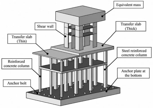
Transfer slab system.
A Transfer Girder is used to transfer the load of the column from the above storeys to the column underneath. Transfer Girders are the major horizontal support system in a structure. They also act as a support for smaller beams. Various numerical analyses revealed that the transfer girder system is an excellent alternative to the slab system for reducing seismic weight and material costs. It is also more flexible than the slab system, thereby reducing strains in the structure's vertical elements.
The transfer slab has several limitations, including a high self-weight and excessive material requirements. Additionally, because of their very large spans and concentrated loads, they may be more prone to deflections and cracking. However, the major drawback of the transfer floor is the abrupt change in lateral stiffness at its level. Therefore, the structure can form a soft-storey mechanism under moderate-to-severe earthquakes. It also imposes high ductility demands on the members near the transfer floors. Lu et al. (1999) advised that irregularity must be properly supervised during the design stages, as it may be the major source of damage to buildings during high-magnitude earthquakes [5].
This review paper on high-rise buildings with transfer floor systems aims to systematically review studies published in the Scopus-indexed database through 2025. The review aims to select novel contributions in the field and has shortlisted manuscripts as indicated in the flowchart (Fig. 2).
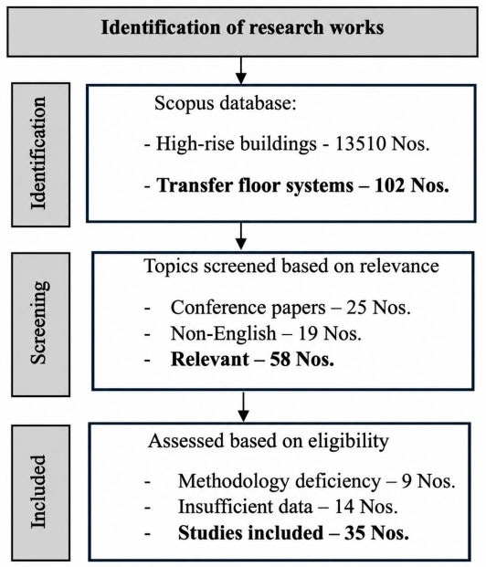
Flowchart for the review.
2. STRUCTURAL BEHAVIOUR OF THE TRANSFER FLOOR SYSTEM
2.1. Comparison of the Performance of Different Transfer-floor Systems
From the drift plots mentioned in the study conducted by Elawady et al. (2014), the girder-type transfer system exhibited more flexible behaviour than the slab type did, especially at and above the transfer floor level [6]. The girder system's flexibility affects drift values, which, in turn, affect the zones near the transfer floor. Linear spectral analyses were carried out on 75-, 50-, 25-, and 10-storey building models. There was a noticeable percentage reduction in both the base shear and moment when transfer girders were adopted instead of transfer slabs (Table 1).
| Building | Action | Transfer Type | Transfer Level with Respect to H | |||
|---|---|---|---|---|---|---|
| 10% H | 20% H | 30% H | 50% H | |||
| 50 - Storey | Base Shear | Slab | 59 | 48 | 41 | 40 |
| Vx | Girder | 55 | 42 | 39 | 39 | |
| % Diff | 8.8 | 14 | 3.2 | 1.5 | ||
| Base Mom. | Slab | 3 | 3.1 | 3.3 | 3.5 | |
| Mxx103 | Girder | 2.8 | 2.9 | 3.1 | 3.4 | |
| % Diff | 6.2 | 6.2 | 5.9 | 4.8 | ||
| Base Shear | Slab | 76 | 55 | 52 | 45 | |
| Vy | Girder | 68 | 51 | 49 | 44 | |
| % Diff | 12 | 6.7 | 3.7 | 2.8 | ||
| Base Mom. | Slab | 2.8 | 2.9 | 3.1 | 3.4 | |
| Myx103 | Girder | 2.7 | 2.7 | 2.9 | 3.3 | |
| % Diff | 2 | 5.1 | 6.3 | 2.5 | ||
However, the analysis concluded that the overall seismic response is unaffected by changing the transfer system from slab to girder. However, this affects the design economy, especially in the storeys below the transfer floor. It also eliminates the rotation effect due to the transfer floor. D’Arenzo (2025) reported that transfer slabs are often modelled as rigid diaphragms [7]. However, research has recommended that transfer slabs or girders be modelled as shells or beam elements rather than rigid diaphragms to account for the flexibility of the transfer floor. This also helps in capturing the true behaviour of the transfer floor structure. Li et al. (2003) reported that in cases with both a transfer slab and a transfer girder, the storey shear force considerably decreased above the transfer floor as a result of mass reduction [8]. Mohamed el Awady (2024) suggested that the transfer slab system is generally more suitable for higher seismic zones (such as zones III and IV). Conversely, the transfer girder system is suitable for locations with lower seismic zones [9]. Mitra et al. (2024) compared transfer beam and transfer truss systems. It was concluded that the storey shear in a transfer truss system was enhanced by approximately 67.2% compared with that in a transfer beam system [10].
Xia et al. (2022) studied a transfer slab with different geometries and reported that, compared with a rectangular or square configuration, a triangular configuration had a shorter time period due to its higher stiffness and lower mass [11]. Furthermore, the maximum base shear was achieved by a pentagon-shaped structure, which was followed by square and circular-shaped structures, and a triangular-shaped structure resulted in a lower base shear value.
2.2. Impact of Transfer Floor Location on Structural Behaviour
Elawady et al. (2014) reported that the location of the transfer floor influenced the structure's global seismic response [6]. Buildings with transfer floors at higher levels responded primarily as single-degree-of-freedom structures, with the fundamental mode controlling the structure's seismic response. The location of the transfer floor within the building height also controls the maximum drift location. Compared with those produced by the higher-level transfer system, the roof drifts produced by the lower-level transfer system were quite high.
Abdlebasset et al. (2016) reported that the drift values at the roof floor are between the values at the transfer floor and the maximum values at two-thirds of the total height [12]. According to the elastic response spectrum analysis, the minimum drift values are at the transfer floor level. This is because of the heavy mass at that level, which in turn causes a high inertial force at that level. Elassaly and Nabil (2017) reported that the highest peak of local damage always occurs on the floor above the transfer system. This peak increases with increasing height of the transfer floor from the base [13]. However, this reduces the building's resistance to ground motion. They suggested locating the transfer floor at 20–30% of the building height. However, this may be constrained by architectural requirements, construction speed, and economy. However, nonlinear analysis revealed that the transfer system at 20% of the building height experienced failure according to Elawady et al. (2014) [6]. The presence of a transfer slab at this height is expected to result in the highest overall damage indices (Abdlebasset et al., 2016) [12]. Shaikh et al. (2020) presented a seismic analysis of a high-rise building with a transfer floor [14]. Five different models of a 10-storey building were studied by providing a transfer slab on the first, second, third, fourth, and fifth floors. They concluded that the vertical location of transfer floors with respect to the total height of the building has a significant effect on the performance of the building and that the introduction of the transfer floor in the lower part of the structure, i.e., 20–30% of the total height of the building from its foundation, is better than having it in a higher location.
Park et al. (2020) evaluated the seismic performance of buildings with a transfer floor in building models featuring a structural wall frame (SWF) and a moment-resisting frame (MRF) [15]. In SWF models, placing the transfer floor on the seventh storey improved overall performance, whereas in MRF models, placing it at lower levels yielded satisfactory results. A study by Mitra et al. (2024) found that when a transfer truss is positioned at the center, buildings with structural walls and a transfer truss system achieve a higher modal mass participation ratio (MPR) of approximately 86% [10]. The location of the transfer trusses and the arrangement of the structural walls strongly affected the modal characteristics. It is suggested to consider the effects of the higher modes. The termination of the structural walls and the different locations of the transfer trusses strongly affected the stiffness ratio between the transfer storeys and conventional storeys. Santhoshi et al. (2025) demonstrated that optimal seismic performance, defined by the lowest inter-storey drift ratio and the best base shear performance, occurs when transfer slabs are situated between 40% and 60% of the total building height [16]. This specific range represents the ideal balance between the building’s seismic weight and its global stiffness. These results reinforce established structural engineering recommendations to avoid stiffness irregularities within the structure, thereby enhancing seismic resilience.
2.3. Effect of stiffness on seismic parameters
A reduction in the stiffness of the horizontal element reduces the seismic forces by 25% compared with the gross inertia for all the elements. A reduction in the stiffness of the vertical elements reduces the seismic forces by approximately 15%. Above 80% of the height of the building above its base, a reduction in stiffness no longer affects the shear and moment values. The reduction in vertical element stiffness is more pronounced above the transfer floor, resulting in a 10% increase in drift. A reduction in the stiffness of the horizontal elements, except for the transfer floor, increases the drift values by 15%. Drift increases by approximately 35% when the stiffness is reduced compared with the gross inertia for all the elements (Abdlebasset et al., 2016) [17].
When the stiffness of the elements is considered for design, high compression strains are expected in the vertical elements because of the combined effect of the shear force and bending moment. A direct consequence of irregularity is that the deformation of a soft-storey mechanism under earthquakes or lateral wind loads imposes high ductility demands near transfer floors (Xia et al., 2022; Lu et al., 1999) [3, 5]. Yoshimura (1997) reported that the sudden change in the lateral stiffness at the transfer floor from a structural wall system above a flexible column-girder system below may create a weak storey and violate the strong column-weak beam concept [18].
Most of the studies focused on high-rise buildings with a single transfer floor level. However, in a few cases, the architect may call for two or more levels of transfer floors, which changes the structure's response. The worst seismic performance occurs in buildings with a transfer floor at lower levels. Notably, for closely spaced transfer floors, the soft storey effect is more prominent, whereas for transfer floors placed at a certain distance, the stiffness of the building is reduced (Su et al., 2022) [19].
Mitra et al. (2024) reported that the storey stiffness increased substantially at the transfer storeys due to the positioning of the transfer truss system and the larger cross-sections of the structural components within the transfer beam system [10]. Owing to the addition of the transfer truss, the ratio of the average stiffness of the transfer storeys to that of the conventional storeys improved from approximately 6.9 to 40.
2.4. Effect of the Transfer Floor on the Base Shear
Li et al. (2003) reported that the presence of a transfer floor increases the base shear value for buildings of all heights [8]. Elassaly et al. (2017) reported that columns beneath the transfer floor experience high storey shear, leading to plastic hinge formation and a soft-storey mechanism [2]. This was due to the higher stiffness at the lower part of the structure. The base shear values resulting from the equivalent static load method are greater than those resulting from the response spectrum method and linear time history method by 70%, whereas the values in linear time analysis are approximately 5 to 10% less than the values obtained in elastic response spectrum analysis (Abdlebasset et al., 2016) [17]. With an increase in the transfer storey level, the ratio of the base shear force to the total weight and the elasto-plastic inter-storey drift ratios might increase or decrease (Wu et al., 2007) [20]. Elassaly et al. (2017) focused on the storey shear diagram and suggested that the higher-mode effect is significant in buildings with lower transfer-floor locations [2]. Lande and Takale (2018) reported that the maximum base shear occurs when the transfer floor is at 10% of the building height [14]. It was determined from case studies that the base shears computed using pushover analysis range from approximately 65% to 83% of those computed using the response spectrum method. However, the base shear determined from the response spectrum in the Saudi Building Code (SBC 301) was significantly lower than that from pushover analysis. El-Bayome et al. (2023) reported that, for the case studies presented in the paper, the base shear derived from pushover analysis ranged from approximately 50% to 83% of that from the static approach [21]. Elawady et al. (2014) reported that, when comparing a girder-type transfer floor system with a solid slab system, decreases in base shear and base moment were observed [6]. This finding held for both lower-level and higher-level transfer floors. Because the lower portion of the structure was stiffer, buildings with lower-level transfer floors had higher base shear than similar buildings with higher-level transfer floors.
2.5. Effect of the Transfer Floor on Drift
Elassaly et al. (2017) considered four models of a 20-storeybuilding: the first model with no transfer slab, and other models with a transfer slab on the first, fourth, and sixth floors [2]. The maximum drift ratios were reduced in the storey where the transfer slab was located. It can be concluded that the podium storeys below the transfer floor are expected to experience high drift ratios, whereas the tower storeys will experience lower drift ratios; this reduction increases with increasing transfer floor level. The curves of the storey drift ratio tend to become nonuniform in the presence of transfer floors. From the drift distributions of the linear response spectrum method, it is evident that the drift demands near the transfer floor are clearly underestimated compared with the drift values obtained from the nonlinear analysis. The roof drifts obtained in the nonlinear analysis are larger than those obtained in the linear elastic analysis, as concluded by Elawady et al. (2014) [6]. Alomari and Maraoa (2022) reported that under seismic stimulation, a thick slab at the transfer floor with columns planted above and widely spaced below does not always result in a soft storey mechanism as long as the lateral storey drift at the transfer level is sufficiently low [7].
2.6. Effect of the Transfer Floor on Deformation
The test models in the study by Zhang et al. (2024) withstood significant earthquake-induced deformation without collapsing, demonstrating good seismic resistance and ductility [22]. Despite the interlayer displacement at the high floors slightly exceeding the maximum value, the upper shear-wall structure did not fail in a relatively rare earthquake. On the basis of equivalent static analysis (ESA) and response spectrum analysis (RSA), Mitra et al. (2024) computed the maximum displacement along the height [10]. The outcomes were quite similar except for the magnitude of deformation. The displacement pattern along the height coincided with the normalised mode shapes and exhibited analogous characteristics. The displacement profile differed among the buildings. The buildings' deformation behavior shifted from flexure to shear, or from both, and vice versa.
2.7. Effect of Transfer Slab Thickness on Design
A change in slab thickness significantly affects the design of every other member in the structure and is therefore not recommended at a later stage of the project, underscoring the importance of selecting an appropriate slab thickness. Dombrowski et al. (2023) stated that the most efficient method of design is to adopt a suitable slab thickness, where the amount of reinforcement is determined on the basis of the structural capacity of the section [23]. The most significant impact of slab thickness was on the slab's bearing and shear capacities. However, a decrease in slab thickness increased the amount of reinforcement, thereby complicating its construction.
Yang et al. (2023) studied the concept of column removal and thereafter evaluated the structural safety of buildings [24]. The influence of column removal is limited to the vertical members surrounding the removed columns. The moments increased after column removal but were still within the transfer slab strength. A transfer slab with a span-to-thickness ratio ranging between 5 and 6 can be laid safely over a removed column, thereby transferring the axial force of the column to the surrounding columns. This finding demonstrated that high-rise buildings with a thick transfer slab between the podium and tower storeys can effectively resist progressive collapse. In contrast to earlier research, Zhang et al. (2024) focused primarily on high-rise structures with thick transfer slabs and used shaking-table tests. In addition to meeting performance objectives, the thick-slab transfer structure prevented serious damage to the bottom frame [22].
2.8. Control of the Increase in Temperature of the Transfer Slab
Tran et al. (2023) reported that there is a significant temperature differential during the heating phase, as the top surface hydrates later and more slowly than at other depths [25]. Limiting heat dissipation at the bottom surface of the concrete while simultaneously rapidly cooling the core of the concrete is key to reducing the temperature difference in the RC transfer slab. In this study, a recommendation was made for the placement of cooling pipes to control thermal cracks. Additionally, to better control the temperature, high-pressure lamps and construction tarpaulin can be utilised to prevent heat loss through the bottom and side surfaces. Michalak P. (2025) determined the heat loss coefficient by transmission between indoor and ambient environments on the basis of measurements and technical data from buildings. To minimise the effects of thermal bridges and cracks, the use of high-quality building materials and high-quality workmanship is crucial [26].
3. CHANGES IN DESIGN CRITERIA DUE TO THE TRANSFER FLOOR
Tattari (2022) identified design challenges and noted that design guidelines are not standardised, thereby making the design of transfer slabs complex [23]. In addition, the cost of construction and design is quite high, and its impact is seen at the entire construction site. Transfer slabs account for the crucial components of the structure, which means that slight modifications of their dimensions may notably affect the design of the other structural components. Slabs are generally designed for gravity loads, even if they are slightly capable of taking lateral loads. However, transfer elements tend to attract considerable lateral loads; therefore, the design must be performed carefully. The location of the transfer floor controls the maximum location for storey drift. Therefore, designers need to take appropriate precautions to satisfy serviceability requirements. The overall seismic response is not affected by the type of transfer floor system used. However, this change affects the design economy, especially in the storeys below the transfer floor level (Elawady et al., 2014) [6]. Wu et al. (2007) concluded that the transfer floor is subjected to shear deformation, which may lead to shear failure, which can be avoided through reasonable design [20]. Thus, there is a substantial increase in sustainability with the careful design of transfer floor structures. Different combinations should be considered when analysing and designing structures. At the transfer floor level, the load transfer from the vertical members above to the columns below abruptly changes, necessitating two-way shear action. To ensure the safety of the structure, an appropriate design for the floor system's two-way shear strength is important. Stirrups are used as shear reinforcement in transfer floor systems to improve the two-way shear strength. Kang et al. (2021) reported that the use of spliced stirrups increased the two-way shear strength of a slab [27]. According to Mitra et al. (2024), to achieve a shorter natural period, it is essential to design buildings with a transfer system that includes structural walls [10]. While some columns failed without damaging the structural walls, transfer beams, or transfer columns, the beams in structures with transfer beam systems experienced considerable damage (over 50%). Therefore, even when structural walls are used, avoiding the construction of structures with transfer systems in high seismic zones is desirable. Alternatively, post-design evaluation of their inelastic behaviour is important. Anantha et al. (2026) compared a base model with a conventional outrigger system and an offset outrigger with a belt truss system, decisively confirming the vital function of outrigger configurations in improving the seismic performance of tall buildings [28]. The results uniformly indicated that both the conventional and offset outrigger designs are highly effective. They significantly mitigate undesirable structural responses, specifically by reducing lateral displacement and storey drift, while concurrently enhancing the base shear capacity of the structure compared to the base model without an outrigger system. The use of a belt truss to asynchronously link the central core to the exterior columns is key to the system's effectiveness. This improved interaction between the core and the peripheral columns is critical, as it leads to a significant reduction in both overturning moments and interstory drifts.
4. PUSHOVER ANALYSIS IN TRANSFER FLOOR DESIGN
The degradation of structural stiffness, the formation, and the locations of plastic hinges under lateral loads can be easily predicted using pushover analysis. The members that are likely to reach the critical stage can be identified during the analysis stage itself by performing a pushover analysis. It saves approximately 20-35% of the reinforced concrete dimensions and reinforcement in buildings. This finding underscores the importance of performing pushover analysis when evaluating buildings with transfer systems, especially in high-seismic regions. Chintanapakdee and Chopra (2004) argued that the modal pushover analysis procedure does not increase in the case of vertical irregularity [29]. There is no deterioration in accuracy despite stiffness or strength irregularities. It is preferable to consider forces generated by earthquake-induced displacements over conventional loads in earthquake resistance design (Paulay and Priestley, 1992) [30]. Sameer and Azeem (2019) reported that, compared with models with a moment-resisting frame (MRF), building models with a structural wall frame (SWF) resulted in a lower effective structural damping; therefore, they concluded that SWF models performed better [15].
5. IMPORTANCE OF CHECKING PUNCHING SHEAR STRESS ON THE TRANSFER SLAB
Byeonguk et al. (2020) verified the accuracy of a separate model (single-storey analysis) for the design of a post-tensioned transfer plate, and the results were compared to those of a complete model (multi-storey building system) [31]. Chaudhari et al. (2026) mention that, in the critical section under the gravity load, the punching shear stress was overestimated in the separate model [32]. However, the punching shear stress calculated using the separate model with a shear wall within the critical section was up to 10% lower than that of the complete model. It was concluded that when the transfer floor is at a higher location, the separate analysis method is not recommended. A separate analysis in such a case is likely to result in insufficient shear design, as the number of storeys below increases at interior columns and at columns without shear walls within the critical section. Additionally, the punching shear stress in the transfer slab below the columns must be carefully verified by designers to ensure it does not exceed the concrete's allowable shear stress (D’Arenzo et al., 2025) [7]. Kang et al. (2021) reported that with a thick slab thickness and a low shear span-to-depth ratio, the top and bottom slab bars in the cross-section of the transfer slab may experience early shear failure in the plain concrete area [27]. Because of this, the structural safety would not be satisfied by the decreased two-way shear strength. Furthermore, the two-way shear strength of the RC transfer slabs was predicted by the strut-tie method [33]. The strut-tie approach worked for RC transfer slabs with symmetric boundary conditions, a shear span-to-depth ratio of less than 2.5, a tension bar ratio of 0.33% to 1.62%, and no web reinforcement. However, more experiments are needed to confirm the validity of the strut–tie method.
CONCLUSION
This review summarises the adaptation of the transfer floor system in high-rise buildings. Transfer floor systems will play a crucial role in high-rise buildings by facilitating the transfer of loads between discontinuous vertical structural members. This ensures better flexibility during architectural planning. Overall, the reviewed studies establish that transfer floor systems introduce complex structural behaviour that requires careful consideration during design and analysis. The structural behaviour of buildings, changes in design criteria, and the relationship between structural stiffness and seismic performance parameters such as natural period, base shear, drift, and lateral deformation are discussed in detail in pushover studies. The reviewed research emphasizes the need for rigorous punching shear verification and the incorporation of appropriate strengthening measures to ensure structural stability and safety.
The transfer floor system is considered the key element for load transfer, and alternative load paths need to be analysed. Alternate load paths are needed to study the structure's ability to redistribute the forces without collapse. Design requirements for improve the floor system's resistance to fire and blast loads can be evaluated for enhance the structure's performance. More research is needed on the ductility of these structural systems, as it is limited by the deformability of the column–slab connection. If the columns and walls terminate at the transfer floor level, evaluating loading on the floor becomes difficult. Further research can be conducted on several planar shapes and their behaviour as a function of the number of storeys above the transfer floor. In some cases, the architect requires two or more levels of transfer floors, which vary the building's response. Therefore, further studies are warranted in such cases. On the other hand, more research is needed on aspects such as the effects of shear reinforcement and rebar distribution to obtain more applicable conclusions. Additionally, the increased straining actions should be taken into consideration when the structural components of the transfer slab system are designed.
LIMITATIONS OF THE REVIEW AND FUTURE SCOPE
The review focuses on investigations that are based on finite element modelling and analytical simulations, while experimental validation and full-scale testing of transfer floor systems remain limited. The structural performance assessment on a real-time monitoring basis might provide a better understanding of the transfer floor system [34].
Future research can focus on nonlinear dynamic behaviour, serviceability, long-term analysis, and full-scale experimental validation of the transfer floor system [35]. The formulation of design recommendations, guidelines, and code provisions will contribute to the effective implementation of the transfer floor system.
AUTHORS’ CONTRIBUTIONS
The authors confirm their contributions to the paper as follows: M.S.: Collected and processed the data and drafted the original manuscript; S.R.G.: Collected and performed an additional literature review and contributed to the original manuscript; S.U.K.: Contributed by supervising the work and review of the manuscript. All authors reviewed the results and approved the final version of the manuscript.
LIST OF ABBREVIATIONS
| RC | = Reinforced Concrete |
| FEA | = Finite Element Analysis |
| SWF | = Structural Wall Frame |
| MPR | = Mass Participation Ratio |
| ESA | = Equivalent Static Analysis |
ACKNOWLEDGEMENTS
Declared none.