All published articles of this journal are available on ScienceDirect.
Numerical Study of Being Forced Leather Cap Type Pig in Straight Gas Pipeline
Abstract
The research on pipeline pigging technology is significant for the operation and management of pipeline. Domestic and foreign scholars usually research the operation rules of pigging in oil pipeline. There are few studies about gas pipeline pigging running because of running rate. The author established the force calculating model and corresponding numerical methods of leather cap type pig in gas pipeline. The model is based on geometric model of oil pipeline pigging. Combining pigging operation parameters with records in September 2013 and February 2014 at Bei Neihuan, the thesis used mathematical method and finite element software respectively to verify the mathematical model. The mathematical results described the average force of cup. The results indicated that the reason of the breaking of the cup is the force, instead of the cup material, temperament extrinsic reasons, etc. The force is larger than the tensile strength of the cup. The results of ANSYS finite element software simulation described the force of different parts of the cup. It is found that the force exceeding of the cup anti-pull force strength in the upper and lower sides of the cup is larger. Both results showed that using the mathematical model can quickly calculate cup pigging force conditions and determine the cause of damage to the cup. It can improve the efficiency of pigging.
1. INTRODUCTION
With the continuous development of the natural gas industry, the pipeline industry has entered a golden stage of development, which has beenconfirmed by the booming global pipeline construction project. Our government has also placed pipeline construction on an important position. China has successively put this into operationin the West-to-East gas pipeline, Sichuan-Eastgas pipeline, China and Myanmar pipeline and so on. These energy arteriesare important to the development of the national economy [1]. Meanwhile, associated piping techniques have also been placed on an important position. An important technology is pipelinepigging technology. Both for a new pipeline and for the pipelines already in operation, pipelinepigging technology has a wide range of applications. Pigging process can not only controlthe insidedirt and impurity in the pipe, but also maintain and monitor the pipeline and reduce equipment wear.
Pipeline pigging technology began in the 1960s. Many scholars not only did many experimental studies about pigging, but also established a number of steady-state and transient pigging mathematical models. One of the most important one is the Minami transient clear management theory. Our country began to promote the pigging technology in the early 1990s. It was initially used in the City water supply pipe network, Oil field sewage pipe network and Oil pipelines [2]. Now, although China has not established complete theory, but a lot of scholars have made a certain number of contribution to the research on pigging. For example, yuxing Li, shuchu Feng have done a lot of research on the pipeline pigging in gas-liquid mixing process. They did more experimental and theoretical studies in their early studies and established a multiphase pipeline pigging mathematical model. YaxinWang has proposedtouse the finite element analysis software-ANSYS to calculate the stress on the pipe cleaner [2]. According to the principles of pipe cleaner andoperation rules, mingZenghas analysed the principle of pipe cleaner operation by using ABAQUS finiteelement analysis software. In the recent years, the research on pigging phenomenon domestically, mainly focuses on oil pipeline pigging, but few studied the gas pipeline pigging [3].
Leather cap type pig has been widely used in pigging in the natural gas pipeline and gas pipe process. Compared with other pigging facilities, leather cap type pig has better cleaning effect. But we also found that the cup was badly worn sometimes or even failed to be applied in the engineering field [4].According to the fundamental data, there are many causes which lead to the failure of the cup , how to quickly find out the cause of pigging injury and propose accurate methods to avoid injury are critical for the improvement of pigging operational efficiency. The wear of leather cap type pig in pigging process is directly related to the pig running friction and shear forces. The size of the force is related to pigging speed, interference of cup, materialpropertiesand other factors. So, we study the force in leather cap type pig while pigging in the gas pipeline. This research studied the force derivation of gas pipeline based on the process of drawing oil pipeline pigging.
2. Pigging force mathematical model
2.1. Pigging Principle
The Pig is driven by gas pressure in front and at the back of the cleaner. The pig is driven to continuously remove the tube dirt while running. When the launcher begin to get into the pipe, the pig speed is greater than the velocity of the fluid. Then, the speed of the pig will constantly decrease until it achieves the equal speed to gas. In this case, the driving force is equal to resistance. The pig has uniform motion, but with the increasing debris in front of the pig, the force in front of pipeline will increase. Especially when the pig gets into the elbow position, the greater is the resistance, the smaller is the speed of the pig , or may eventually come to ahalt. At that point, the block force of the rear gas and the driving force increases, and the pigging speed will gradually increases. From this, we can conclude that pig movement in the pipeline is a non-stationary process [5]. The speed is close to the airflow velocity in the straight pipe deformation. The pig speed changed a lot in roll to the deformation and elbow part. To make the pig running smoothly, impetus provided by pipeline must be larger than its resistance, otherwise, there will be incidents of stuck pipe. Pigging diagram is shown in (Fig. 1).
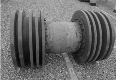
Pigging diagram.
2.2. Pig Stress Analysis
According to the pigging principle, the author thinks that the basic laws of different pigging process flowsare the same, which are Gas-liquid continuity equation, Momentum conservation equation and Energy conservation equation. So, the kind of force that gas pipeline pigging suffered is the same to that of oil pipeline. Pigging force is shown in (Fig. 2). Horizontal direction is α=0̐. The main force is: the fluid pressure in front and at the back of the cleaner, own gravity component (it can be neglected to consider the state in a horizontal tube), Pipe friction, and Shear resistance tube sedimentary layers [4].
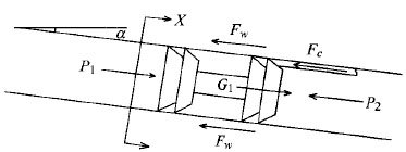
Schematic of forced pigging.
In this research, we assume that the gas is an incompressible fluid(the gas can be seen as an incompressible fluid when the gas velocity is less than 50 m/s which a predetermined level in engineering. The pig running speed is less than 20 m/s [6]) the Viscosity remain unchanged, it can get formula (1) by hydrodynamic momentum theorem.
 |
(1) |
Pigging suffered friction size of formula (2).
 |
(2) |
We make A2 concrete. The friction that pig suffered is indicated in formula (3).
 |
(3) |
The shear stress that Pig suffered is shown in formula (4), the stress is shown in formula (5).
 |
(4) |
 |
(5) |
Then, we brought (5) to (4) and we get formula (6).
 |
(6) |
In the above formulas (1) to (6), the physical symbol is explained as follows:
Where S is the cross-sectionalareaofthe pipe, m2; n is the number of cups installed on the pig; ε is the interferenceof cup; A2 is the contact area between the wall and pig, m2; f is the coefficient of sliding friction between pig and pipe wall; l is the length of contactingbetween cup and pipe wall, m; d is the inside diameter of Pipe, m; D is the outside diameter of cup, m; m is the quality of pig, kg; E is the elastic modulus of cups material, Pa; g is theacceleration of gravity, m/s2; de is the equivalent to the inner diameter of the cup, m; µ is the viscosity of the fluid in the pipe, mPa.s; l1 is the length of Pigging, m; vs is the pigging instantaneous velocity, m/s; e is the roughness between pigging and wall, m.
According to the introduction of SYT 5922-2012 natural gas pipeline operations, the pressure ΔP in front and at the back of the cleaner is shown in (7).
 |
(7) |
In summary, we can get the force mathematical model that leather cap type pig suffered in gas pipeline. The equation is shown in (8).
 |
(8) |
Where ΔP is the pressure in front and at the back of the cleaner, MPa; p1* is the starting pressure of pig, MPa; p2* is the gaspressure in currentstation, MPa; p3* is themaximum elevation of fluid within the tube pressure, MPa, the study is negligible.
3. METHODS
3.1. Software Simulation of Pigging Model
During the operation of leather cap type pig in gas pipelinepigging, the phenomenon of surface to surface contact between cup and pipe wall occurs. The cupis considered as flexible interface with large deformation andpipe wall is regarded as rigid contact surface, respectively [7]. The author established the contactmodel of the contact between pigging and pipe wall of Bei Neihuan pipelinein September2013, analyzed the results of the stress on cup and node displacementby using the finite element software ANSYS10.0. ANSYS can solve the problems of surface contact between flexible-rigid surfaces. In the actual cleaning process, the pig showed severe deformation and the cup is seriously damaged. Now, the author introduces the important steps in resolving the problem.
3.2. Solving Process
3.2.1. The First Step: The Description of the Issue
The qualities of pipe material: The material of the pipe is L485(16MnR, low alloy steel). The elasticity modulus, Poisson's coefficient, inner diameter and length are 2100 MPa, 0.3, 813mm and 30mm, respectively.
The qualities of the cup: The elasticity modulus and Poisson's coefficient are 1.2 MPa and 0.47, respectively.
Physical dimension:The diameter of sealed cup and thickness are 822mm and 30mm, respectively. The speed of pig is 3.05m/s and the friction coefficient between the cup and pipe wall is 0.8. The magnitude of interference is 3.4%.
3.2.2. The Second Step: The Establishment of Physical Model
According to the description of the previous step of the problem, combined with the physical model pigging, the three-dimensional geometric model in ANSYS was established. Its three-dimensional model is shown in (Fig. 3).
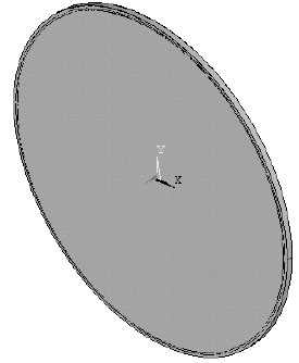
Three-dimensional model.
According to the geometric model and Setting unit property as follows:
(1) Definition of unit type
Add library of pipeline element types>structural solid>brick 8 node 185;
Add library of cup element types>structural solid>brick 8 node 185;
(2) Definition of material properties
Define material model behaviors>structural>linear>elastic> isotropic;
Define pipeline property: linear isotropic property for material> EX=2.1e9, PRXY=0.3.
Add cup property: linear isotropic property for material> EX=1.2e6, PRXY=0.47.
3.2.3. The Third Step: Meshing
The mesh is divided by the method of free mesh division. Preliminary classification of the mesh is conducted by using line Size Ctrls. Then meshing>meshing tool>setting volume>mesh and then optimize by controlling the size and shape. There are 2595 nodes and 11083 units in the 3D model.
As shown in Fig. (4), a 3D model is established and analyzedthe stress of one sealed cup.
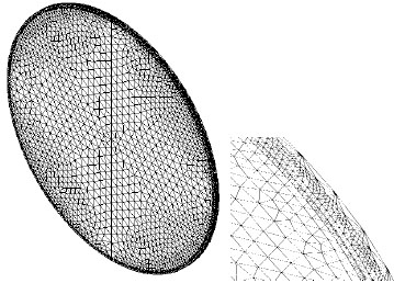
Cup with a wall dividing the catenary grid and enlarged schematic diagram.
3.2.4. The Forth Step: Applied Load
(1) Define the boundary conditions. The targetsurface is the inner wall of the steel tube and the contact surface is a leather bowl material.
(2) Impose the symmetric displacement restraint. The axis of symmetry for a quarter of the model set in two interface displacements is zero.
(3) Apply the plane constraint condition. Make the cross section of the pipe fixed and displacement zero.
(4) Apply the node displacement. Set all the node displacements in the Z axis direction which is 15 mm, and the maximum displacement is 30 mm.
3.2.5. The Fifth Step: The Solution of Physical Model
As shown in Fig. (5), Mises stress nephogram of model contact analysis is obtained by calculation. As shown in Table 1, the node displacement table has been obtained.
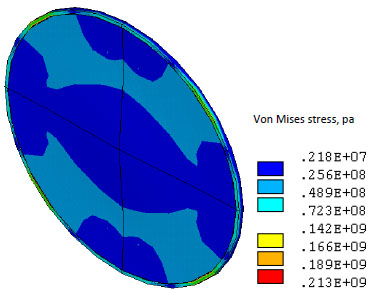
Von Mises stress cloud of cup in contact with the wall when the interference.
| Node | X-axis displacement, mm | Y-axis displacement, mm | Z-axis displacement, mm | Total displacement, mm |
|---|---|---|---|---|
| 4 | 0.0000 | 0.0000 | 2.5000 | 2.5000 |
| 1510 | 0.0000 | 0.0000 | 2.5000 | 2.5000 |
| 1536 | 0.0000 | 0.0000 | 2.5000 | 2.5000 |
| 1590 | 0.0000 | 0.0000 | 2.5000 | 2.5000 |
| 1602 | 0.0000 | 0.0000 | 2.5000 | 2.5000 |
| 1619 | 0.0000 | 0.0000 | 2.5000 | 2.5000 |
| 1651 | 0.0000 | 0.0000 | 2.5000 | 2.5000 |
| 1738 | 0.0000 | 0.0000 | 2.5000 | 2.5000 |
| 1762 | 0.0000 | 0.0000 | 2.5000 | 2.5000 |
| 1814 | 0.0000 | 0.0000 | 2.5000 | 2.5000 |
| 1831 | 0.0000 | 0.0000 | 2.5000 | 2.5000 |
| 1831 | 0.0000 | 0.0000 | 2.5000 | 2.5000 |
| 1861 | 0.0000 | 0.0000 | 2.5000 | 2.5000 |
3.2.6. The Sixth Step: Analysis of the Results
We can find that the maximum stress area appears on the contact interference on the surface, and the maximum stress is 213 MPa, which is far greater than the cup strength 35MPa by analyzing the stress nephogram data. Rubber cup performance indicators are shown in (Table 2). The indicators meet the standard specifications like GB/T528-2009, GB/T 531.1-2008, GB/T 1689, GB/T 1862-1994, GB/T 1681. It demonstrates that the cup has been damaged, which is in accordance with the actual condition and illustrates the correctness of the mathematics model again.
| Project | Indicators |
|---|---|
| Tensile strength, MPa | ≥35 |
| Elongation at break, % | ≥500 |
| Permanent deformation rate, % | ≤10 |
Shore A hardness, 
|
75±5 |
| Impact resilience, % | ≥30 |
| Wear, ml/1.61 km | ≤0.05 |
| Brittleness temperature, °C | ≥-35 |
From the part of the node displacement, we can see that the cup produces displacement along the Z axis and X/Y-axis displacement is 0, which demonstrates the deformation of cup is serious and corresponds to the actual condition by analyzing the curve of the node displacement of the contact between cup and pipe wall. Therefore, effective measures must be taken to improve the cup and enhance the efficiency of pigging.
4. RESULTS AND DISCUSSION
4.1. Examples of Verification
Bei Neihuan pipeline is a new Branch of Southwest Oil and Gas Field Company. The pipe is also an important pipeline in the ring network of the Gas Transmission Department of Southwest Oil and Gas Branch. The pigging process has the following characteristics [8].
- The pigging process is a long distance. It is up to more than 150 kilometers. It takes an average time of more than 800 minutes to end;
- Under the normal production status, the pigging process is operated in large and open diameter pipeline;
- Gas Pipeline mixed condensate in midway. Condensate is highly risky and flammable.
The basic situation of Bei Neihuan pipe is as follows:
The pipe’s specifications is Φ813×11. The length of pipeline is 159 km. The speed of pigging is 3.97 m/s. The output of pipeline is 550×104 m3/d. In February 2014, the maximum pressure of pushing the pig was 0.5 MPa. The pressure difference from beginning to end is 0.39 MPa. Pigging running is in good conditions. Coefficient of friction is 0.8. Cups material elastic modulus is 1.2 M8Pa. The viscosity of the fluid conduit is 0.4576mPa.s. Roughness between pigging and wall is 0.01mm [9]. Pigging size is given in (Table 3).
| Bi-cup size | Seal cup, mm | Number, a | Length of Pigging, m | The amount of interference | Anti-pull strength, MPa | Total weight of cup, kg |
|---|---|---|---|---|---|---|
| Φ813 | 822*30 | 6 | 1.3 | 3.4% | ≥22.5 | 210 |
Based on pipe pigging records of Bei Neihuan pipe in February 2014, we analyze the stress of pig. Among them:
Δp = 0.5+0.39 = 0.89MPa
 |
Then, we calculate the resultant force.
F = FThrust-FW–FC = 8.93×10⁵–0.1776×10⁵–6.09×105 = 2.6624×10⁵N
We analyze the force of per unit area of the cup:
 |
The average pressure of cups suffered is 0.513 MPa. The pressure is smaller than the tensile strength. Besides, the length of the pig meet the requirements [10]. The result is consistent with the facts andthis verified the applicability of the model.
CONCLUSION
Based on hydrodynamic basic theory, the research analyzed the forces in pipeline pigging during pigging and get the following conclusions.
- The article established pig force model during pigging.
- In accordance with the pigging record and basic data during pigging of Bei Neihuan pipeline in September 2013 and February 2014, the article calculated pigging force and simulated software modeling. These verified the correctness and reliability of the model.
- When stressing calculation and analysis, using finite element analysis software ANSYS to analyze pigging was found to be convenient.
- According to pigging basic data, the simple mathematical model can quickly determine the reason of pigging cup’s breakage, it can also provide reference for improving the efficiency of the pig.
CONFLICT OF INTEREST
The authors confirm that this article content has no conflict of interest.
ACKNOWLEDGEMENTS
This research is supported by the project in Petrochina southwest oil and gas field company. The project name is Pig run mechanics performance analysis and structure optimization.


