All published articles of this journal are available on ScienceDirect.
Stress Analysis of Suspended Pipe Partially Buried in Linear Elastic Soil
Abstract
Based on the small deflection beam theory, bending equation with axial tension of suspended pipe partially buried in the linear elastic soil is established. And the corresponding boundary conditions are given according to the stress and deformation characteristics of suspended section and buried section. Then deflection equation for the suspended section is deduced. Afterwards, the stress and critical length of a suspended pipeline are calculated and analyzed. The results show that the tensile stress and bending stress on the endpoint of the suspended section meet the requirement of first strength theory and the critical suspended length is greater than the real suspended length, which is consistent with the actual situation. When the stiffness of soil tends to approach infinity, both the limit value of axial tension and endpoint bending moment agree well with the calculation results of fixed-fixed supported beam model.
1. INTRODUCTION
In recent years, oil and gas pipeline construction projects have been developing rapidly. And some long distance pipelines pass through areas with complex geological environment, where the pipelines may be affected by geological disasters such as debris flow, landslide, flash floods and earthquake and so on. In these cases, long-span suspension of pipelines is prone to occur and the safety of pipeline is seriously threatened [1, 2]. In view of this phenomenon, the existing specifications suggest that the fixed-fixed supported beam model and simply articulated beam model should be applied in suspended pipeline stress analysis [3, 4]. And some studies have been conducted based on the two models [5-7]. However, since the pipeline is partially buried in soil, the loads of the suspended section include not only its own gravity but also the axial force and resistance of foundation soil in the process of pipe transverse deformation. Therefore, neither fixed-fixed supported beam model nor simply articulated beam model is applicable, because there is a certain disparities between the two models and actual situation [8]. In order to get more realistic and available results, especially for pipelines partially buried in linear elastic soil, the mechanical model of suspended pipeline with axial tension and resistance of foundation soil is built based on the small deflection beam theory in this paper. Besides, a case study is carried out and the results can be applied in practical engineering.
2. MODEL OF SUSPENDED PIPELINE
There will be a flexural deformation caused by gravity after the pipeline accidentally suspends in the air. In this case, the diameter and transverse deflection y1(x) of the pipeline is far less than its suspended length. So it is appropriate to apply the small deflection beam theory to calculate the bending deformation [9-11]. For analytic convenience, the mechanical model of the pipeline is built (Fig. 1).
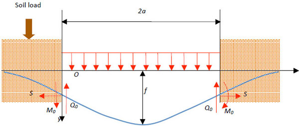
Schematic diagram of suspended pipeline model.
In this model, the pipeline is regarded as a slender beam or rod and we assume that the buried segment is quite long. Furthermore, the rectangular coordinate system is established and we take the junction of the left end of the suspended segment and the buried segment as the origin, while the horizontal equilibrium position of the pipeline being treated as the x axis. In addition, we use the following notations for easy expression:
2a: Length of the suspended segment
kb: Stiffness of the linear elastic soil
EI: Bending rigidity
S: Axial tension
q: Vertical uniformly distributed load
M0: Endpoint bending moment
Q0: Endpoint shearing force
f: Maximum deflection of the suspended segment
2.1. Governing Differential Equation
According to the small deflection beam theory, the deflection equation of the suspended segment can be expressed as:
 |
(1) |
The deflection equation of the buried segment can be expressed as:
 |
(2) |
2.2. Boundary Conditions
The general solution of Eq. (1) is:
 |
(3) |
The general solution of Eq. (2) is:
 |
(4) |
where:
 , ,
|
 |
Considering the displacement boundary conditions of the embedded section at negative infinity, it is obtained that:
 |
(5) |
When x = 0, the suspended segment deflection y1(x) satisfies with the following conditions:
 |
(6) |
According to the continuity conditions at the join points of buried section and suspended section, the following expressions are obtained:
 |
(7) |
Moreover, the symmetric buckling characteristic of suspended section are expressed as:
 |
(8) |
2.3. Coefficients Calculation
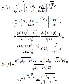
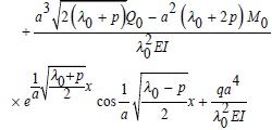
Substituting Eqs. (5)~(8) into Eq. (1) and Eq. (2), the coefficients are obtained:
 |
(9) |
3. CASE STUDY
3.1. Materials
In a certain district , a buried pipeline gets suspended due to the geological disasters. The suspended length is up to 320 m and the deflection is 7 m. Other parameters of pipe are shown in (Table 1). Moreover, it is known that the oil density is 0.8×10³ kg/m3 and the soil stiffness coefficient is 106 N/m2.
| Material | External diameter, mm | Wall thickness, mm | Elasticity modulus, GPa | Density material, kg/m3 | Yield strength, MPa |
|---|---|---|---|---|---|
| X 52 | 219.1 | 6.4 | 210 | 7.85×10³ | 360 |
3.2. Results and Discussion
3.2.1. Axial Tension and Endpoint Bending Moment Calculation
In the fixed-fixed supported beam model, the axial tension and endpoint bending moment are calculated as follows [12]:
 |
(16) |
 |
(17) |
According to Eq. (16), the axial tension S could be obtained if deflection f and uniformly distributed load q were given making use of the repeated iteration method. We can know from the calculation that the value of S is 1051 kN and its corresponding tensile stress is 252.6 MPa. According to Eq. (17), it is figured out that the value of M0 is 205110 N∙m and its corresponding bending stress is 198.2 MPa.
On the basis of Eq. (13), the value of S is 1083 kN and the corresponding tensile stress is 253.3 MPa. While the value of M0 is 78057.9 N∙m and the corresponding bending stress is 75.4 MPa. Additionally, the relationship between strain and deflection, as well as that between strain and endpoint bending moment are found out (Fig. 2 and Fig. 3). It is obviously that the deflection and endpoint bending moment decrease with the increase of the axial tension.
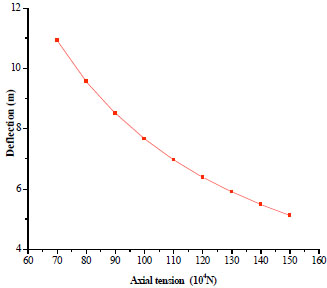
Axial tension and deflection relation curve.
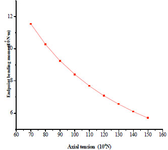
Axial tension and endpoint bending moment relation.
Similarly, the axial tension and endpoint bending moment are figured out with different soil stiffness (Fig. 4 and Fig. 5). The figures shows that as soil stiffness increases, the axial tension decreases while the endpoint bending moment increases. Besides, the changes of axial tension and endpoint bending moment start to level off with the increase of the soil stiffness. When the soil stiffness tends to approach infinity, the limits of axial tension and endpoint bending moment are 1051 kN and 20511 N∙m, respectively, which are the same as the results of fixed-fixed supported beam model.
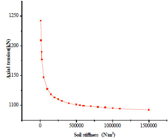
Axial tension change curve with different soil stiffness.
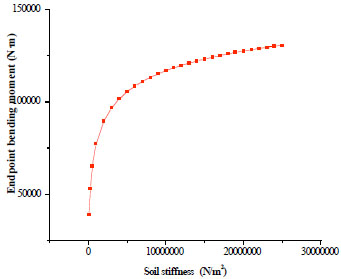
Endpoint bending moment change curve with different soil stiffness.
3.2.2. Critical Length of Suspended Segment
The stress equals to the allowable strength of pipeline when the suspended segment length is up to the critical value. According to the first strength theory, the tensile stress σ of an object is supposed to be less than its buckling strength [σ], namely σ ≤ [σ]. By calculation, we can see the critical length is 381 m. Besides, the relation curve between the critical length and deflection is shown in (Fig. 6).
3.2.3. Pipeline Safety Analysis
The yield stress of the pipeline [σ] = 360 MPa, while the maximum tensile stress σ = 253.3 MPa and the maximum bending stress σ0 = 75.4 MPa, all of which are less than the yield stress. Besides, we can figure out that the critical suspended length of this oil pipeline is 381 m. And it matches the actual situation that the pipeline is not pulled apart when the suspended length reaches 320 m.
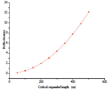
Critical suspended length and deflection curve.
However, in order to ensure the safety of oil and gas pipeline, “Code for design of oil and gas transportation pipeline aerial crossing engineering” (GB50459-2009) introduced the strength design coefficient C to revise the material yield strength. It is required that the pipe stress caused by bending deformation should be no more than the product of strength design coefficient C times material yield strength [σ]. That is:
 |
In this case, the oil pipeline with 320 m suspended section belongs to the large aerial crossing engineering and the strength coefficient should be 0.55. So the revised allowable stress is C[σ] = 198 MPa, which is less than the pipe maximum tensile stress. Therefore, this suspended pipe doesn’t meet the specification for the allowable stress according to “Code for design of oil and gas transportation pipeline aerial crossing engineering”. It means that there is security risk when pipe is running and it is suggested for the pipeline to be halted.
CONCLUSION
In this paper, the deflection equation of suspended pipeline partially embedded in line elastic soil is established and the relationships between axial tension and deflection, as well as endpoint bending moment are demonstrated by a case study. Based on the calculation results, we can see that, as the tension increases, the deflection and endpoint bending moment actually decrease. And the results show that both the axial tension and endpoint bending moment meet the first strength theory. Meanwhile, the critical suspended length is bigger than the actual suspended length, which matches actual situation and indicates that the mechanical model can reflect the realities of mechanics in pipeline. Besides, it is proved that the fixed-fixed supported beam model is applicable only for the pipe buried in rigid soil.
CONFLICT OF INTEREST
The authors confirm that this article content has no conflict of interest.
ACKNOWLEDGEMENTs
Declared none.

