All published articles of this journal are available on ScienceDirect.
Research on Seismic Performance of Reinforced Concrete Frame with Unequal Span Under Low Cyclic Reversed Loading
Abstract
In order to investigate the seismic performance of reinforced concrete frame with unequal span, a specimen was tested under low-cyclic loading and the seismic performance of this frame was analyzed based on fiber element method using software OpenSees. Hysteretic curves, skeleton curves, ductility, stiffness degradation and energy dissipating capacity of the frame are compared and analyzed. The experimental and simulate results demonstrate that this frame has a poor seismic performance. Thus, it is suggested that the seismic strengthening criteria of unequal-span frame structure should be raised and the existing buildings of this structure should be retrofitted.
1. INTRODUCTION
Many school buildings including those of reinforced concrete (RC) frame structural system have suffered severe damage during earthquakes. The seismic performance of RC frames has been extensively studied by a number of experts. Mpampatsikos et al. [1] assess the seismic behavior of two existing reinforced concrete frames according to Eurocode 8 and Italian seismic code, by checking the ductility mechanisms and brittle mechanisms of those structures. Bilgin [2] believes the structural system of school buildings in Turkey has poor seismic bearing capacity and proposes to strengthen them by adding shear wall in longitudinal and transverse direction, through evaluating the seismic performance of a four-storey reinforced concrete frame. Shrestha et al. [3] investigate the vulnerabilities of 58 buildings of 19 school in Aceh, Indonesia by onsite test and partially destructive test, and compare the cost-effect of retrofitting approach and rebuilt approach.
After Wenchuan Earthquake, seismic damages of RC frames structural buildings [4] are investigated. A number of systematic researches in China have been carried out on the basic seismic performances of frame structures and failure characteristics from the perspectives of frame beams [5, 6], frame columns [7, 8], frame joints [9, 10] and the whole structures [11-15].
Xuankou School building [16-19] is a typical RC frame structure with two unequal spans, which is a popular structure in Primary and middle school in China. Please refer to Fig. (1) for the destroyed Xuankou School building.
In order to evaluate seismic performance of the structure such as Xuankou School building, this study examines a 1/2 scale two-storey and two-bay RC frame designed in accordance with Chinese code for seismic design of buildings (GB50011-2010), adopting pseudo-static approach.
Based on the assumption of small deformation and plane section, fiber element method [20, 21] is widely used in numerical analysis and has been verified to be effective to assess nonlinear response of braced frames [22-26] and evaluating the capacity of precast-prestessed slabs [27, 28]. This method is suitable to different sections since it discretizes the cross-section into fibers. Furthermore, it is relatively more accurate as the element section force deformation relation is derived by integration of the stress-strain relation of the fibers.
Both the experimental results and numerical analysis using software OpenSees verify this structure has poor seismic performance.
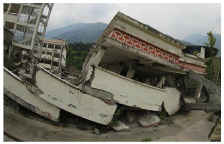
Collapse of Xuankou Middle School building.
2. EXPERIMENTAL PROGRAM
2.1. Test Specimen
The test specimen is two-storey and two-bay RC frame structure, with span lengths of 3.0m and 1.2m. The frame is at 1/2 scale with storey height of 1.5m and total height of 3.6m. The cross sections of the beams and columns are 150mm by 250mm and 200mm by 250mm, while the ground beam is 350mm by 400mm. The compressive cube strength of the concrete, based on the average value obtained from coupon tests, is 23.8MPa. The longitudinal reinforcements in beams and columns employ HRB335, with diameter of 16mm, yield strength of 425MPa and ultimate strength of 565MPa, while the stirrups in beams and columns apply HPB235, with diameter of 8mm, yield strength of 305MPa, ultimate strength of 445MPa. The dimensions and the reinforcements of the frame are depicted in Fig. (2).
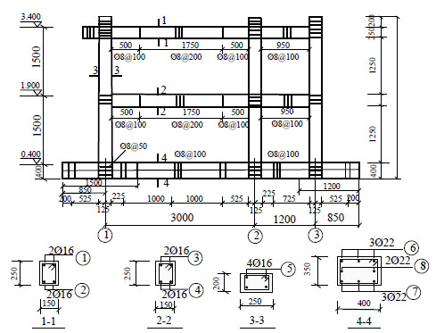
Dimensions and reinforcement detail.
2.2. Test Setup and Instrumentation
The specimen is subjected to quasi-static cyclic loading on beam end of the second floor. As shown in Fig. (3), the specimen is bolted to the rigid floor through the six holes in the base girder. Constant vertical loads of 150kN (to simulate gravity load to this specimen when axial load ratio is 0.25) are applied to the three column tops by three mechanical jacks. The mechanical jacks are connected to the steel beam by roller bearings, which maintain free horizontal displacement of the frame under vertical loads and horizontal loadings. The horizontal cyclic loadings are imposed by a servo-hydraulic actuator made by Beijing Fluid Control System Corp. Loading of the specimen is illustrated in Fig. (4). The test instruments are preloaded to ensure the stability at initial stage. The application of simulation cyclic loads is based on a hybrid force/displacement control. Before yield of specimen, the test is at force control stage. The specimen is loaded one cycle at each force level with loading value of 20kN. When the specimen yielded, the test reached the displacement control stage. The specimen is loaded two cycles at every displacement level while the loading value is integral multiples of yield displacement.
When the displacement reaches 4Δy and the current capacity of the specimen decreases to 85% of maximum bearing capacity.
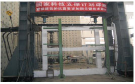
Test setup.
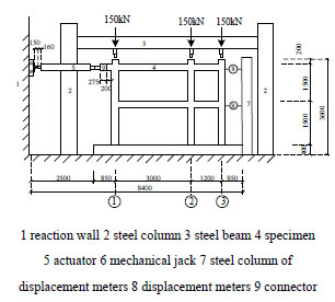
Test setup.
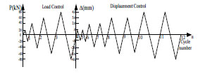
Loading program.
2.3. Test Description
The failure pattern is illustrated in Fig. (5). In the area of 5cm-6cm away from beam end, some diagonal cracks in length ranged from 7cm to 12cm appear at first. Then the cracks extend to the mid-span of the beam and some cracks are observed in the area of 10cm-38cm away from the beam end. When the loading reaches -60kN, an 8cm long crack appears at bottom of the column on the first floor. When the loading reaches 70kN, some cracks appear in the area 28-36cm away from the top of columns. At the stage of displacement control, the cracks of the columns extend further and even run through the whole cross-sections of columns, while the longitudinal reinforcements of beams begin to yield. After the yield, the cross diagonal cracks at the joint zone grow, and the specimen reaches splitting failure in the end. At the later stage of the loading, the “zi, zi” sound comes from the inside of the frame, the concrete peels partially at the beam end, bottom of the column and joints region. When the current capacity of the specimen decreases to 85% of maximum bearing capacity, the specimen reaches its ultimate state.
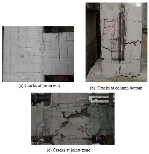
Specimen failure pattern.
2.4. Numerical Simulation
The reinforcement concrete frame is simulated using software OpenSees based on fiber element method, adopting nonlinear beam-column elements with 6 integrate points. The beam and column elements are defined respectively for the different confinement of stirrups. The data would be more accurate and ideal if the plastic hinge element is considered. To avoid too complicated numerical model the plastic hinge model was not added in this study.
2.4.1. Strain-Stress Relationship of Steel
A uniaxal Giuffre-Menegotto-Pinto steel material object with isotropic strain hardening is taken into consideration in the steel material named Steel02 in OpenSees. The yield strength and modulus of steel are obtained from test results and parameters to control the transition from elastic to plastic braches named R0, CR1 and CR2 are 18, 0.925 and 0.15. The stress-strain curve of steel is shown as Fig. (6a).
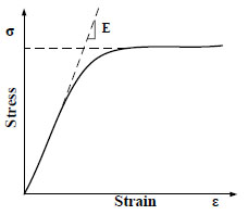
Steel stress-strain curve.
2.4.2. Stress-Strain Relationship of Concrete
The Concrete02 material object in OpenSees software is employed in this concrete frame. The epsco is concrete strain at the maximum stress point, f pc is concrete compressive cylinder strength, epsU is concrete strain at the crushing strength, fpcu is concrete crushing strength, λ is the ratio between unloading slope at crushing strain and initial slope, ft represents concrete tension strength and Ets is tension softening stiffness. In this model, the initial elastic modulus Ec is got from the test, which value is 2.42×10⁵N/mm2. The stress-strain curve of concrete is illustrated in Fig. (6b).
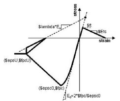
Steel stress-strain curve.
The stress-strain relationships of covered concrete and core concrete (confinement of stirrups) are considered as follows:
(1)The cylinder strength fc1 is taken as maximum strength of covered concrete, its value is 0.76 times cubic compressive strength according to core for design of concrete structures [29], the strain at maximum stress point is taken as epsco = 2× fc1/2Ec and the values of stress and strain at crushing strength point are as follows: epsU = –0.0038 fpcu = 0.2fc1 λ = 0.1 the tension strength is, ft = 0.1 fc1 and the tension elastic modulus is Ets = 0.1 Ec.
(2) The values of core concrete are calculated in accordance with Mander’s method [30], which are fpc, epsco at maximum stress point and fpcu, epsU at crushing strength point. As the configurations of stirrups are different in the columns, ends and mid-span of the beams, confinement on different core concrete parts varies. In accordance with the confinement of stirrups, the core concrete elements of beam and column can be divided into three elements:
- Column elements confined by stirrups;
- Beam elements confined by stirrups;
- Covered concrete elements.
The core concrete element types are illustrated in Fig. (7).
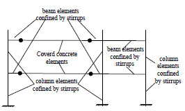
The core concrete elements of beams and columns.
3. RESULTS AND DISCUSSION
3.1. Hysteretic Curve
The hysteretic curves of the horizontal load on the specimen and the displacement on the top of the second floor are shown in Fig. (8). At the beginning of loading, the hysteretic curve is almost linear and the slope is quite steep. With the increase of loads, the specimen starts to crack; when the specimen reaches the yield point, the hysteretic loop becomes plumper. When the loading is under displacement control, the curve becomes smoother; the stiffness of specimen is degraded gradually, and the hysteretic loop begins to present pinch phenomenon. When the components have obvious slip, the specimen tends to fail and the hysteretic loop is on reverse S-shape.
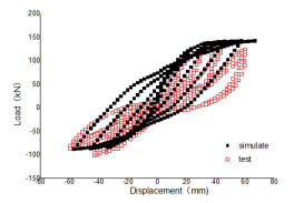
Hysteretic curve.
There is a little deviation between the experimental data and numerical data in Fig. (8). The two results would be more consistent [31] if the factors such as plastic hinge element, cracks and bond-slip were taken into consideration.
3.2. Skeleton Curve
The skeleton curve of the specimen is depicted in Fig. (9). It can be observed that at the beginning of loading, the curve is linear in state and the specimen is in elastic stage. With the increase of the loading, the specimen enters the plastic stage, the cracks grow gradually and the stiffness decreases. Therefore, the slope of skeleton decreases gradually, and tends to X axis direction. When the loading reaches 80kN, the slope of skeleton deceases tremendously, the curvature speeds up its decrease rate. The curve slope becomes negative after the maximum load point, while the load decreases gradually with the increase of displacement until it reaches the ultimate load. The structural bearing capacity decreases rapidly with cracks growing gradually, following the increase of loading during test process. On the contrary, structural bearing capacity decreases slowly during the simulate process. It is because that numerical model is ideal without taking cracks [32, 33] into account. While, in reality the cracks would significantly influence the strength, stiffness, ductility and other parameters of concrete structures.
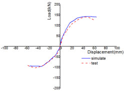
Skeleton curve.
Test results and ductility factor.
| Specimen | Direction | Test | Model |
|---|---|---|---|
| Yield load | positive | 94.25kN | 106.5kN |
| negative | 66.04kN | 94.8kN | |
| Yield displacement | positive | 19.69mm | 106.5mm |
| negative | 19.05mm | 94.8mm | |
| Maximum load | positive | 142.4kN | 19.98 kN |
| negative | 103.8 kN | 18.72 kN | |
| Maximum displacement | positive | 44.7 mm | 45.5mm |
| negative | 44.2mm | 36.8mm | |
| Ultimate Load |
positive | 120.7kN | 140.3 kN |
| negative | 88.0 kN | 93.9 kN | |
| Ultimate displacement | positive | 61.2mm | 64.1mm |
| negative | 57.2mm | 54.5mm | |
| Ductility factor | positive | 3.1 | 3.2 |
| negative | 3.0 | 2.9 |
3.3. Ductility Analysis
Yield load and displacement are calculated using general yield moment method, and maximum load and displacement, ultimate load and displacement of the specimen generated from hysteretic curve and skeleton curve offer data for the calculation of ductility coefficient. As shown in the experimental results and ductility coefficient of Table 1, the load in the positive direction is higher than that in reverse direction, which is caused by the damaged accumulation of the frame. Although the ductility coefficient of the frame is higher than the coefficient of 3.0 in normal cases, this relatively low value indicates the poor ductility performance. It also demonstrates that the reinforced frame is vulnerable to severe destruction when subjected to external load.
3.4. Stiffness Degradation Curve
Stiffness degradation curve of the specimen is shown in Fig. (10). It can be observed that the secant stiffness decreases with the increase of displacement, which indicates the trend of stiffness degradation of the frame. Secant stiffness drops suddenly from 10kN/mm to 6kN/mm, which illustrates the rapid stiffness degradation caused by the appearance of new cracks and growth of old ones. The specimen has the maximum stiffness at the early stage, and then it degrades gradually with the growth of cracks and accumulation of internal damage. When the loading gets 80kN and corresponding secant stiffness reaches 4.13, the frame begins to yield, the primary cracks are formed and the stiffness degradation becomes relatively stable. After that, the stiffness degradation ratio becomes slower until the specimen reaches its ultimate state.
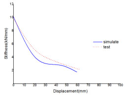
Stiffness degradation curve.
3.5. Energy Dissipation Curve
The equivalent viscous damping factor [34] is calculated based on the areas of hysteretic loop and corresponding triangle. The relation curve of equivalent viscous damping coefficient and corresponding displacement is depicted in Fig. (11). As can be seen in Fig. (11), the equivalent viscous damping factor grows with the increase of displacement, but the ratio of increase has little change. The increase of equivalent viscous damping coefficient proves a gradual growth of energy dissipation of specimen, while the minor change in the ratio of increase indicates that the frame has low energy dissipation capacity, which corresponds to the pinching phenomenon of hysteretic loop in Fig. (9).
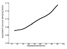
The graph of equivalent viscous damping coefficient.
Even though the equivalent viscous damping factor is slightly overestimated as stated by Brunesi [35], it correctly reflects energy dissipation trend of the structure. The small area of hysteretic loop confirms that the RC frame has poor energy dissipation capacity.
CONCLUSION
Focused on the seismic performance of two-story and two-span RC frame under low cyclic loading, the following conclusions can be drawn from the numerical analysis and experimental results of the research:
- The reverse S-shape of hysteretic curve of the test results demonstrates that the frame has a low energy dissipation capacity. This is because the stiffness degraded severely when the concrete cracks, the longitudinal reinforcement yields, the cracks grow significantly at the bottoms of three columns, and the variation of displacement exceeds the variation of loads, and the components slip tremendously.
- The data of yield load and displacement, maximum load and displacement, ultimate load and displacement from hysteretic curve show the difference between positive and reverse loading, while the difference of data is mainly caused by damage accumulation during loading on the frame. The displacement ductility coefficient of approximately 3.0 demonstrates that the frame has low deformability.
- The frame stiffness degradation is remarkable before the main crack formed. After that, the secant stiffness decreases with the increase of displacement but the ratio of decrease is slow, which shows that the frame stiffness degradation grows slower. The frame energy dissipation curve increases with the increase of displacement, which confirms that the energy dissipation of the specimen is becoming stronger. Because of the pinching phenomenon of hysteretic loop, the ratio of energy dissipation increase is small, which indicates that the frame has low energy dissipation capacity.
- The ideal model is used in numerical simulation without taking into account the impacts of cracks in the frame, reinforced slip and other factors, thus there are some deviations between simulate and experimental results.
- Although the RC unequal-span frame is widely used in primary and middle school buildings in China, its seismic performance is relatively poor. Therefore, it is necessary to raise the seismic strengthening criteria of unequal-span frame structure and to retrofit the existing buildings of this structure.
CONFLICT OF INTEREST
The authors confirm that this article content has no conflict of interest.
ACKNOWLEDGEMENTS
This study was financially supported by National Natural Foundation of China in 2012(No.51178259) and Postgraduate innovation fund of Shandong University Science and Technology (No. YC150328).


