All published articles of this journal are available on ScienceDirect.
Comparative Experimental Study and FE Analysis of Corrugated Steel Pipe Culverts with Different Stiffness
Abstract
This paper describes comparative experiment on corrugated steel pipe culverts with different stiffness. The two culverts both with 1.2m span and 4m backfill height but with different corrugation pattern and plate thickness were constructed side by side. Displacement, strain and soil pressure at critical points were tested during construction. Two-dimensional (2D) finite element (FE) models were established and the computed values were compared with measured values to verify the effectiveness of FE models and the reasonability of the test. The study shows that the deformation trend is the same but the deformations of the flexible pipe were much larger. Only after the backfill finished and the soil-structure bear the load together the FE simulation could basically reflect the stress state of the structure due to the nonlinearity of soil and the complexity of soil-structure interaction. The larger deformation of the flexible pipe makes the soil-structure interaction obvious, which reduces the pressure of backfill soil on the structure. Therefore realities should be considered when choosing corrugation pattern and thickness of corrugated plates to optimize design and save construction cost.
1. INTRODUCTION
Flexible metal types of culverts are getting more and more popular in recent years because they are more economical and have shorter construction periods compared to traditional bridges and culverts [1]. However, since the soil and structure properties have a great influence on deflection, stress and earth pressure, the stress state of the structures are difficult to be accurately predicted during and after construction. Therefore, many tests and finite element (FE) comparative studies have been conducted to investigate the behavior of such structure.
K.M.El-Sawy used three-dimensional (3D) FE to analyses two existing soil-steel culverts. By comparing with the measured data and theoretical (3D FE) results, he stated that the results of the 3D FE analyses for the thrusts compared well with the experimentally measured ones with differences less than 30%. The FE results for bending moments showed less agreement which may be due to the sensitivity of the bending moments to the accurate modeling of the properties of the soil material [2]. B. Kunecki conducted a static test on a corrugated steel culvert in the laboratory to measure its strain, displacement and earth pressure. He compared the data with FE model analyses to obtain the results that the measured and computed displacements were in a close agreement, but the axial stresses were less agreement with the values measured, being significantly higher [3]. Shad Sargand conducted field test on a 6.4m diameter corrugated steel pipe culvert which was erected and buried under a 22.9m highway embankment in Ohio. The field performance of the culvert was monitored by measuring the earth pressure distribution around the pipe, as well as the deflections of the pipe culvert during and after construction. The study also included comparing measured field performance with numerical predictions given by the FE computer program CANDE-89. Field measurements and observations suggest that positive soil arching may have been induced by a combination of ring compression (bending) and circumferential shortening experienced by the steel pipe [4]. Kyong Y. Yeau presented the results of field performance tests of 39 in-service corrugated steel highway culverts in Ohio. Static and dynamic load tests were conducted by driving heavy trucks across the culverts. The results showed that culvert deflections decreased nonlinearly with increasing soil backfill height. Maximum deflections measured during dynamic truck loading were approximately 10-30% less than corresponding maximum deflections for static truck loading [5]. L. Korusiewicz investigated the behavior of steel box-type culvert during backfill with full-scale tests. The results showed that measured displacements and stresses were approximately equal about the culvert symmetry axis, the degree of that symmetry being higher as the soil depth rises. The obtained experimental results were compared with the structure response computed using the FE model. The adopted FE model proved to be incapable of determining displacements and internal forces in the culvert at the initial stages of backfilling since it took no account of soil compacting forces [6]. Z. MAŃKO tested a single-span road bridge made from Super Cor corrugated steel plates, with 12.315m span. The average values of the displacements and strains measured in the selected elements of the steel shell structure were much lower than the ones calculated for the same load by FE model [7]. R. W. I. Brachman tested a deep-corrugated steel culverts with a bottom span of 10 m, an inside rise of 2.4m, and a width of 6m. Comparisons are made between the two sets of calculations and measured values of displacement and circumferential strain, moment and thrust are calculated from measured strain. The corrugated analysis provided calculated values much closer to those that were measured, whereas values from the orthotropic analysis erred by much greater amounts, particularly in the vicinity of loading points in which the orthotropic analysis cannot model local effects [8]. Z. J. Feng presented a laboratory model test of a corrugated steel pipe culvert with 1m radius during backfilling, which testified that the deformation laws of circumferential tension or compression at wave crest or wave trough are consistent, no matter the test points are in or outside the corrugated steel pipe culvert. The earth pressure on the culvert crown can be defined as the design parameter for the culvert with high filling [9]. Kyong Y. Yeau investigated through numerical simulations using the established modeling properties. Summarized that deflections predicted from the two-dimensional analyses were larger than the deflections measured in the field. The experimental and calculated thrust forces were similar. Deflections and thrust forces predicted from the three-dimensional analysis were similar to the experimental results. The critical factors affecting the response of the culverts include cover depth, culvert size, metal thickness, and elastic modulus and other properties of backfill soil [10].
From the above papers of tests on corrugated steel pipe culverts, we can know that most of them focus on comparative test and FEM analysis of a certain test or some field projects. Many tested results have been compared with calculated results and different conclusions have been drawn after analyzing. But the comparative study on corrugated steel pipe culverts with different stiffness has not been conducted. In this paper, two culverts both with 1.2m span and 4m backfill height but with different corrugation pattern and plate thickness are selected for comparative test and FEM analysis. The displacement, strain and earth pressure of the two pipes in the critical points are tested during construction. By analyzing and comparing the measured data with the FEM results, some general regulations in the deformation, internal forces and earth pressure distribution of the corrugated steel pipe culverts with different stiffness are obtained. The study shows that the deformations of the flexible pipe were much larger which makes the soil-structure interaction obvious. It reduces the pressure of backfill soil on the structure. Therefore, realities should be considered when choosing corrugation pattern and thickness of corrugated plates to optimize design and save construction cost.
2. DESCRIPTION OF THE COMPARATIVE TEST
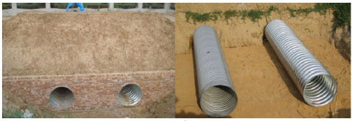
As is shown in Fig. (1), two pipes with different stiffness are located in a foundation pit with the form of 6.5m long and 7.2m wide. The two pipes both with 1.2m diameter have the distance of 2.4m from each other and 1.2m far from the edge of the foundation pit. The two pipes both have 4m backfill soil height and are 6.5m long.

As is shown in Fig. (2), a slope with the rate of 1:1.25 is filling above a brick retaining wall which is constructed on the left side of the pipes. On the other side of pipes, a natural vertical slope is used to restrain the backfill soil. The pipes are blocked by the end wall. The test sections are selected at 1.5m far from the end wall (located at the maximum backfill height). The pipe with larger relatively rigidity (the following is called relatively rigid pipe) is assembled by corrugated steel plate with sinusoidal corrugations (pitch P and depth D is 200mm×55mm) and the plate thickness t is 3.5mm. As for the pipe with smaller rigidity (the following is called flexible pipe), which is a spiral pipe with sinusoidal corrugations (pitch P and depth D is 125×25mm) and the plate thickness t is 1.6mm. The base steel of the two pipes is Grade Q235 with yield stress of 235 MPa.
3. ARRANGEMENT OF MEASURING POINTS
3.1. Arrangements of Strain Measuring Points
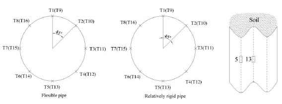
Strain gauges were placed at 8 locations inside the steel culverts. Two gauges were fitted to each location, one at the top and one at the bottom of the corrugation (total 16 strain gauges). Strain gauges had the resistance of 120 Ω and factor k equal to 2.20. Fig. (3) shows the geometry of the culverts and the locations of the strain gauges on the test section.
3.2. Arrangements of Displacement Measuring Points
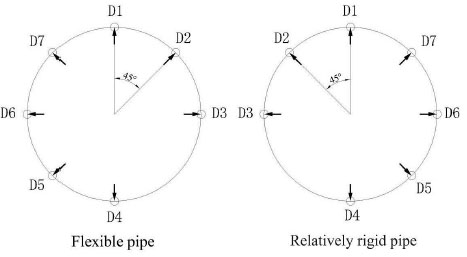
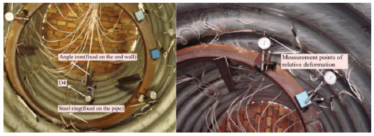
Displacement measuring points were basically same with shear strain measuring points. As is shown in Fig. (4), displacement gauges were placed at 7 locations in the test section inside the culverts. Displacement gauges in Number 4 (D4) was fixed on the end wall which was set outside of the culverts to measure the absolute deformation. The other points of displacement gauges (D1-D3, D5-D7) allowed a relative displacement of the culvert to be measured. The actual photo of displacement gauges is shown in Fig. (5).
3.3. Earth Pressure Cells Arrangement
In order to study the interaction between soil and the structure, the earth pressure cells were installed on both sides and the top of two pipes and also on the same test section. Number 1-4 earth pressure cells were installed on the sides of two pipes to measure the horizontal earth pressure. Number 5-7 earth pressure cells were installed at the crown lever of the pipes to measure the vertical earth pressure. Additionally, number 8-17 earth pressure cells were installed in the soil at the lever with distance of 0.5m, 1.5m and 3m from the crown lever of the pipe. The arrangement of the earth pressure cells is shown in Fig. (6). According to “Technical Specification for Construction of Highway Bridge and Culverts(JTG-2011) [11]”, the left side of the Figure shows the plan of the backfill layers. Each of the layers is 20-25 cm height except the last layer. JXY-4 earth pressure cells were used.
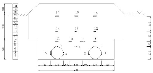
4. BACKFILLING PROCESS AND ARRANGEMENT OF MEASURING ITEMS
From layer 1 to layer 9, each layer has a thickness of 20cm and should be filled symmetrically with required degree of compaction. From the beginning of layer 10, each layer has a thickness of 25cm and should be filled symmetrically with required degree of compaction. For the last layer, the thickness is 40 cm. The total backfill height is 4m and the required degree of compaction should be guaranteed more than 90%. All the layers were backfilled with sand by artificial compaction except the last layer of 40cm was backfilled with clay by mechanical consolidation. The data of strain and displacement should be recorded for every backfill layer. Earth pressure cells were placed at the arrangement positions during the backfilling construction. From the beginning of backfilling, earth pressure cells and displacement gauges should be recorded for every backfill layer.
5. TEST RESULTS
Test results of the displacement, earth pressure and stress during backfill are listed in Tables 1-5.
| Relatively rigid pipe | |||||||
|---|---|---|---|---|---|---|---|
| Backfill height(cm) |
Points | ||||||
| D1 | D2 | D3 | D4 | D5 | D6 | D7 | |
| 0 | 0 | 0 | 0 | 0 | 0 | 0 | 0 |
| 20 | 0.032 | 0.025 | 0 | -0.11 | 0.09 | 0.035 | 0.02 |
| 40 | -0.072 | -0.026 | -0.026 | -0.043 | 0.098 | 0.02 | -0.023 |
| 60 | -0.04 | 0.006 | -0.03 | 0.109 | 0.138 | 0.036 | -0.001 |
| 80 | -0.134 | -0.124 | -0.083 | 0.112 | 0.325 | 0.16 | -0.046 |
| 100 | -0.159 | -0.116 | -0.043 | 0.116 | 0.398 | 0.187 | -0.056 |
| 120 | -0.121 | -0.044 | 0.015 | 0.124 | 0.262 | 0.133 | -0.032 |
| 140 | 0.059 | 0.063 | 0.021 | 0.287 | 0.122 | 0.061 | 0.089 |
| 160 | 0.161 | 0.17 | 0.063 | 0.29 | -0.001 | -0.035 | 0.103 |
| 180 | 0.267 | 0.254 | 0.084 | 0.183 | -0.101 | -0.113 | 0.178 |
| 205 | 0.55 | 0.675 | 0.315 | -0.963 | -0.471 | -0.503 | 0.152 |
| 230 | 0.704 | 0.792 | 0.352 | -1.035 | -0.589 | -0.563 | 0.236 |
| 255 | 0.784 | 0.865 | 0.36 | -1.2 | -0.694 | -0.637 | 0.27 |
| 280 | 0.953 | 0.999 | 0.413 | -1.061 | -0.846 | -0.739 | 0.35 |
| 305 | 1.099 | 1.129 | 0.45 | -1.023 | -1.01 | -0.865 | 0.44 |
| 330 | 1.219 | 1.154 | 0.396 | -0.985 | -1.126 | -0.89 | 0.593 |
| 355 | 1.399 | 1.378 | 0.524 | -1.008 | -1.332 | -1.136 | 0.662 |
| 380 | 1.66 | 1.664 | 0.666 | -1.075 | -1.589 | -1.366 | 0.673 |
| 405 | 1.854 | 1.869 | 0.724 | -1.076 | -1.794 | -1.55 | 0.763 |
| 430 | 2.154 | 2.127 | 0.794 | -1.163 | -2.089 | -1.785 | 0.935 |
| 455 | 2.372 | 2.258 | 0.831 | -1.072 | -2.246 | -1.902 | 0.982 |
| 480 | 2.827 | 2.628 | 0.918 | -1.463 | -2.647 | -2.216 | 1.226 |
| 520 | 3.063 | 2.822 | 0.966 | -1.533 | -2.885 | -2.413 | 1.284 |
| Flexible pipe | |||||||
|---|---|---|---|---|---|---|---|
| Backfill height (cm) |
Points | ||||||
| D1 | D2 | D3 | D4 | D5 | D6 | D7 | |
| 0 | 0 | 0 | 0 | 0 | 0 | 0 | 0 |
| 20 | 0.103 | 0.053 | -0.004 | 0.371 | -0.055 | 0.026 | 0.055 |
| 40 | -0.181 | -0.194 | -0.112 | 0.227 | 0.154 | 0.341 | 0.092 |
| 60 | -0.203 | -0.186 | -0.062 | 0.369 | 0.236 | 0.407 | 0.048 |
| 80 | -0.684 | -0.728 | -0.074 | 0.221 | 0.635 | 1.047 | 0.125 |
| 100 | -0.993 | -0.917 | 0.098 | 0.105 | 0.745 | 1.323 | 0.145 |
| 120 | -1.08 | -0.845 | 0.242 | 0.107 | 0.627 | 1.302 | 0.208 |
| 140 | -0.885 | -0.378 | 0.249 | -0.367 | 0.362 | 0.823 | 0.074 |
| 160 | -0.428 | 0.043 | 0.03 | -0.506 | -0.029 | 0.378 | 0.188 |
| 180 | -0.103 | 0.355 | -0.014 | -0.658 | -0.286 | 0.089 | 0.276 |
| 205 | 2.571 | 2.653 | -1.129 | -2.115 | -0.953 | -2.439 | 0.817 |
| 230 | 2.735 | 2.753 | -1.16 | -2.156 | -1.023 | -2.535 | 0.883 |
| 255 | 2.937 | 2.92 | -1.301 | -2.222 | -1.211 | -2.708 | 0.987 |
| 280 | 3.088 | 3.145 | -1.283 | -2.273 | -1.394 | -2.925 | 0.981 |
| 305 | 3.3 | 3.33 | -1.313 | -2.281 | -1.461 | -3.096 | 1.016 |
| 330 | 3.446 | 3.662 | -1.376 | -2.321 | -1.808 | -3.429 | 1.032 |
| 355 | 3.644 | 3.916 | -1.42 | -2.264 | -2.019 | -3.651 | 1.106 |
| 380 | 3.905 | 4.349 | -1.398 | -2.224 | -2.318 | -4.074 | 1.065 |
| 405 | 4.096 | 4.702 | -1.377 | -2.113 | -2.585 | -4.432 | 1.044 |
| 430 | 4.386 | 5.135 | -1.46 | -1.874 | -2.935 | -4.879 | 1.038 |
| 455 | 4.506 | 5.299 | -1.477 | -1.693 | -3.047 | -5.007 | 1.069 |
| 480 | 4.806 | 5.738 | -1.478 | -1.265 | -2.921 | -5.479 | 1.059 |
| 520 | 5.045 | 6.102 | -1.526 | -0.835 | -2.92 | -5.891 | 1.041 |
| Relatively rigid pipe | ||||||||
| Backfill height(cm) |
Points | |||||||
| T1 | T2 | T3 | T4 | T5 | T6 | T7 | T8 | |
|---|---|---|---|---|---|---|---|---|
| 0 | 0 | 0 | 0 | 0 | 0 | 0 | 0 | 0 |
| 20 | -9.66 | -2.73 | -2.1 | -3.78 | -6.51 | -11.13 | -4.2 | -7.77 |
| 40 | -45.99 | 7.77 | 15.96 | -12.18 | -24.15 | -34.65 | 22.89 | 2.94 |
| 60 | -74.13 | 12.18 | 38.85 | -19.74 | -47.88 | -58.8 | 58.8 | 19.53 |
| 80 | -27.51 | 30.66 | 50.61 | -2.52 | -11.13 | -6.93 | 16.38 | 23.94 |
| 100 | -49.14 | 40.32 | 72.45 | -11.97 | -30.03 | -38.64 | 47.67 | 16.59 |
| 120 | -89.04 | 24.15 | 63.84 | -26.25 | -57.75 | -87.36 | 65.31 | 74.13 |
| 140 | -57.75 | 48.51 | 95.97 | -21 | -27.3 | -81.9 | 68.04 | 83.79 |
| 160 | -78.54 | 25.83 | 75.81 | -19.74 | -43.68 | -98.28 | 55.65 | 54.81 |
| 180 | -63.21 | 41.79 | 95.76 | -18.27 | -26.04 | -81.48 | 57.33 | 81.27 |
| 205 | -54.18 | 43.89 | 81.06 | -1.89 | -13.86 | -79.17 | 54.39 | 63.63 |
| 230 | -38.22 | 58.17 | 98.49 | 1.68 | 3.78 | -65.1 | 52.08 | 84.42 |
| 255 | -39.27 | 52.92 | 104.4 | -2.73 | 3.36 | -70.56 | 51.03 | 96.18 |
| 280 | -25.41 | 62.79 | 74.55 | -6.72 | 19.74 | -70.77 | 44.94 | 59.64 |
| 305 | -27.09 | 59.85 | 66.99 | -9.66 | 20.58 | -60.9 | 44.94 | 47.46 |
| 330 | -35.28 | 59.22 | 60.48 | -23.94 | 18.9 | -72.03 | 49.77 | 42.42 |
| 355 | -33.39 | 61.53 | 62.79 | -23.94 | 24.15 | -77.07 | 49.35 | 49.35 |
| 380 | -26.04 | 67.83 | 61.74 | -23.73 | 36.96 | -87.57 | 45.15 | 54.6 |
| 405 | -23.1 | 70.35 | 57.75 | -25.83 | 43.05 | -82.53 | 41.79 | 54.39 |
| 430 | -21.21 | 71.4 | 56.7 | -36.12 | 52.08 | -78.33 | 49.35 | 56.91 |
| 455 | -15.33 | 76.23 | 59.01 | -43.89 | 60.27 | -81.69 | 34.44 | 63.21 |
| 480 | -1.47 | 85.05 | 68.04 | -47.67 | 76.65 | -60.06 | 0 | 80.22 |
| 520 | -1.05 | 84.21 | 64.26 | -40.32 | 81.69 | -56.7 | 13.23 | 78.75 |
| Backfill height(cm) |
Points | |||||||
| T9 | T10 | T11 | T12 | T13 | T14 | T15 | T16 | |
| 0 | 0 | 0 | 0 | 0 | 0 | 0 | 0 | 0 |
| 20 | 0 | 1.31 | -10.5 | 0 | -12.39 | -9.66 | -16.8 | -11.55 |
| 40 | -0.21 | 45.11 | 25.41 | -6.09 | -43.89 | -49.56 | -56.07 | 40.53 |
| 60 | 6.09 | 86.52 | 68.25 | -18.3 | -68.46 | -80.85 | -91.35 | 83.79 |
| 80 | 10.5 | 80.22 | 87.99 | -1.89 | -12.81 | -31.92 | -31.29 | 74.34 |
| 100 | -18.48 | 82.59 | 115.29 | -8.19 | -41.79 | -48.72 | -64.05 | 75.6 |
| Backfill height(cm) |
Points | |||||||
| T9 | T10 | T11 | T12 | T13 | T14 | T15 | T16 | |
| 120 | -12.18 | 165.93 | 91.35 | -16.6 | -93.66 | -81.48 | -119.07 | 156.66 |
| 140 | -17.43 | 144.27 | 104.16 | -7.14 | -89.67 | -61.53 | -108.99 | 137.13 |
| 160 | -2.52 | 154.51 | 100.17 | -3.15 | -104.58 | -76.65 | -120.96 | 112.14 |
| 180 | -16.17 | 157.82 | 122.64 | 0.84 | -89.67 | -60.69 | -102.9 | 143.85 |
| 205 | -22.47 | 136.51 | 116.34 | 16.17 | -88.2 | -47.04 | -90.93 | 119.49 |
| 230 | -27.09 | 159.57 | 139.23 | 21.42 | -77.49 | -30.24 | -75.18 | 144.9 |
| 255 | -17.85 | 165.43 | 147.63 | 15.12 | -83.79 | -47.88 | -79.38 | 154.98 |
| 280 | -30.45 | 108.39 | 102.69 | 17.22 | -94.08 | -38.85 | -72.66 | 102.06 |
| 305 | -24.57 | 115.24 | 107.73 | 18.06 | -88.83 | -44.1 | -60.69 | 103.53 |
| 330 | -30.66 | 123.48 | 101.01 | 6.3 | -104.37 | -70.35 | -73.92 | 94.71 |
| 355 | -39.06 | 129.36 | 107.52 | 3.36 | -107.94 | -65.94 | -74.76 | 100.17 |
| 380 | -43.89 | 127.47 | 101.22 | 1.89 | -120.75 | -58.17 | -78.75 | 89.88 |
| 405 | -44.52 | 126 | 107.31 | 2.73 | -119.91 | -58.17 | -69.93 | 92.82 |
| 430 | -47.46 | 120.33 | 119.91 | -7.56 | -124.11 | -72.66 | -61.95 | 101.01 |
| 455 | -53.76 | 117.39 | 119.07 | -11.1 | -131.67 | -69.09 | -61.95 | 101.01 |
| 480 | -52.92 | 146.63 | 146.79 | -15.5 | -117.6 | -63.84 | -36.54 | 134.19 |
| 520 | -53.55 | 145.66 | 153.93 | -7.35 | -117.6 | -72.66 | -28.77 | 138.6 |
| Flexible pipe | ||||||||
| Backfill height(cm) |
Points | |||||||
| T1 | T2 | T3 | T4 | T5 | T6 | T7 | T8 | |
| 0 | 0 | 0 | 0 | 0 | 0 | 0 | 0 | 0 |
| 20 | 14.7 | 12.6 | 9.66 | 6.51 | 1.26 | 2.31 | 1.68 | 12.81 |
| 40 | 22.89 | 12.18 | 7.98 | 12.39 | -13.65 | -5.67 | -8.4 | 31.29 |
| 60 | 27.3 | 14.49 | 2.31 | 15.33 | -27.93 | -15.54 | -14.91 | 55.44 |
| 80 | 11.55 | 10.92 | 35.49 | 34.65 | -14.91 | -3.78 | 21.42 | 49.56 |
| 100 | 15.96 | 17.01 | 37.8 | 16.17 | -26.25 | -21 | 18.9 | 69.93 |
| 120 | 24.36 | 19.32 | 24.15 | 6.3 | -28.98 | -29.61 | 0.21 | 94.29 |
| 140 | 36.33 | 42.42 | 41.16 | 12.81 | -21 | -21 | 6.72 | 84 |
| 160 | 21.84 | 13.86 | 4.41 | -1.47 | -26.25 | -31.5 | -27.51 | 86.31 |
| 180 | 14.49 | 7.77 | -5.04 | -21.21 | -38.43 | -53.34 | -31.5 | 65.31 |
| 205 | 70.98 | 51.45 | -21.21 | -11.76 | 34.02 | -24.57 | -59.01 | 94.92 |
| 230 | 57.54 | 37.59 | -35.7 | -28.14 | 13.23 | -47.88 | -49.14 | 70.77 |
| 255 | 53.97 | 30.24 | -45.99 | -31.5 | 11.13 | -54.18 | -76.02 | 67.41 |
| 280 | 48.93 | 31.71 | -48.3 | -63.84 | 2.73 | -66.36 | -87.36 | 55.02 |
| 305 | 48.09 | 26.88 | -52.92 | -72.03 | 5.67 | -68.88 | -96.39 | 57.75 |
| 330 | 33.39 | 9.24 | -75.39 | -89.25 | -3.36 | -84 | -127.05 | 45.57 |
| 355 | 37.59 | 12.18 | -75.39 | -87.99 | 2.1 | -85.47 | -126.63 | 48.3 |
| 380 | 40.53 | 17.85 | -77.49 | -93.03 | 6.3 | -87.78 | -129.99 | 46.41 |
| 405 | 42 | 19.74 | -80.64 | -97.23 | 10.29 | -87.78 | -137.34 | 49.77 |
| 430 | 45.78 | 24.15 | -86.1 | -98.49 | 19.32 | -85.26 | -144.48 | 53.55 |
| 455 | 43.68 | 22.47 | -89.04 | -106.26 | 13.23 | -93.66 | -132.3 | 44.31 |
| 480 | 64.05 | 47.25 | -72.24 | -93.66 | 33.6 | -79.17 | -114.66 | 56.7 |
| 520 | 43.68 | 25.2 | -99.54 | -116.97 | 16.59 | -99.96 | -150.15 | 36.75 |
| Backfill height(cm) |
Points | |||||||
| T9 | T10 | T11 | T12 | T13 | T14 | T15 | T16 | |
| 0 | 0 | 0 | 0 | 0 | 0 | 0 | 0 | 0 |
| 20 | 11.13 | 13.23 | -7.14 | -1.68 | -9.03 | -3.99 | -1.68 | -7.98 |
| 40 | 20.79 | 39.48 | 116.55 | 13.02 | -29.61 | 51.03 | 57.54 | -24.57 |
| 60 | 27.72 | 57.96 | 112.35 | 39.06 | -42.42 | 82.32 | 113.61 | -28.77 |
| 80 | 9.03 | 31.71 | 135.24 | 0 | -10.29 | 121.8 | 67.62 | -8.61 |
| Backfill height(cm) |
Points | |||||||
| T9 | T10 | T11 | T12 | T13 | T14 | T15 | T16 | |
| 100 | 17.22 | 43.26 | 125.16 | 20.58 | -28.98 | 114.03 | 85.89 | -17.43 |
| 120 | 47.88 | 73.92 | 107.52 | 36.75 | -49.77 | 135.66 | 114.45 | -35.07 |
| 140 | 30.66 | 70.98 | 118.02 | 52.08 | -47.88 | 140.91 | 125.79 | -24.36 |
| 160 | 15.96 | 52.71 | 112.98 | 63.63 | -63.84 | 152.67 | 126.42 | -47.67 |
| 180 | -2.1 | 36.33 | 119.07 | 71.19 | -64.26 | 167.79 | 136.08 | -32.97 |
| 205 | -10.5 | 48.51 | 152.67 | 80.85 | -101.22 | 119.7 | 152.46 | -44.73 |
| 230 | -31.71 | 27.72 | 155.4 | 83.16 | -98.91 | 145.32 | 159.39 | -32.13 |
| 255 | -39.06 | 23.1 | 155.61 | 85.05 | -100.8 | 176.82 | 168.63 | -36.54 |
| 280 | -61.32 | 0.84 | 155.4 | 86.31 | -111.09 | 54.39 | 141.33 | -35.07 |
| 305 | -65.31 | -2.94 | 152.88 | 84.63 | -113.61 | 31.29 | 135.03 | -41.37 |
| 330 | -84.84 | -21.21 | 157.29 | 94.5 | -112.56 | 38.64 | 143.01 | -38.01 |
| 355 | -84.84 | -21.21 | 155.61 | 97.86 | -115.71 | 55.44 | 145.74 | -38.22 |
| 380 | -90.93 | -28.77 | 155.4 | 101.64 | -122.64 | 55.02 | 149.94 | -38.22 |
| 405 | -93.03 | -32.97 | 155.4 | 104.37 | -127.68 | 43.68 | 148.05 | -41.16 |
| 430 | -93.03 | -34.02 | 166.53 | 109.83 | -124.74 | 69.09 | 166.74 | -36.33 |
| 455 | -101.43 | -42.21 | 155.19 | 99.96 | -138.81 | 60.27 | 157.29 | -45.15 |
| 480 | -89.25 | -30.87 | 130.2 | 72.87 | -172.83 | 39.9 | 133.14 | -64.26 |
| 520 | -111.3 | -52.29 | 149.1 | 92.82 | -158.55 | 74.13 | 157.92 | -51.24 |
| Backfill height(cm) |
Points | ||||||||
| 1 | 2 | 3 | 4 | 5 | 6 | 7 | 8 | 9 | |
| 60 | 0 | 0 | 0 | 0 | - | - | - | - | - |
| 80 | 0.003 | 0.00475 | 0.0025 | 0.002222 | - | - | - | - | - |
| 100 | 0.003 | 0.00425 | 0.00175 | 0.001975 | - | - | - | - | - |
| 120 | 0.004 | 0.0055 | 0.001 | 0.002469 | 0 | 0 | 0 | - | - |
| 140 | 0.00375 | 0.00475 | 0.00175 | 0.002469 | 0 | 0.00275 | 0.001266 | - | - |
| 160 | 0.0045 | 0.006 | 0.00325 | 0.004198 | 0.00325 | 0.00675 | 0.006582 | 0 | 0 |
| 180 | 0.00575 | 0.00725 | 0.0045 | 0.005679 | 0.006 | 0.0115 | 0.010886 | 0.001795 | 0.001266 |
| 205 | 0.006 | 0.0065 | 0.005 | 0.005185 | 0.01225 | 0.02025 | 0.029799 | 0.010769 | 0.008354 |
| 230 | 0.0075 | 0.00775 | 0.0075 | 0.008148 | 0.0205 | 0.025583 | 0.034599 | 0.019487 | 0.01038 |
| 255 | 0.01075 | 0.0095 | 0.01025 | 0.011111 | 0.023967 | 0.03305 | 0.038332 | 0.024768 | 0.01443 |
| 280 | 0.012 | 0.011 | 0.0125 | 0.013827 | 0.0285 | 0.039183 | 0.041532 | 0.030173 | 0.018734 |
| 305 | 0.0125 | 0.01175 | 0.014 | 0.015802 | 0.031167 | 0.043906 | 0.043399 | 0.034768 | 0.022025 |
| 330 | 0.01525 | 0.01325 | 0.01525 | 0.017284 | 0.0389 | 0.048628 | 0.047288 | 0.039633 | 0.023892 |
| 355 | 0.01525 | 0.01475 | 0.017 | 0.02 | 0.042367 | 0.055017 | 0.050344 | 0.04583 | 0.029225 |
| 380 | 0.0155 | 0.016 | 0.0185 | 0.021558 | 0.0507 | 0.06085 | 0.050621 | 0.052309 | 0.033759 |
| 405 | 0.0165 | 0.01675 | 0.01975 | 0.023117 | 0.0582 | 0.065778 | 0.05201 | 0.057379 | 0.036959 |
| 430 | 0.0175 | 0.0185 | 0.021 | 0.024675 | 0.073852 | 0.071575 | 0.054232 | 0.066823 | 0.042025 |
| 455 | 0.019 | 0.0195 | 0.022316 | 0.025974 | 0.083549 | 0.076212 | 0.05701 | 0.071823 | 0.046251 |
| 480 | 0.0195 | 0.0215 | 0.023895 | 0.027792 | 0.111312 | 0.082365 | 0.062844 | 0.086796 | 0.05273 |
| 520 | 0.0205 | 0.02275 | 0.025211 | 0.029091 | 0.124999 | 0.087214 | 0.066961 | 0.095281 | 0.0578 |
| Backfill height(cm) |
Points | ||||||||
| 10 | 11 | 12 | 13 | 14 | 15 | 16 | 17 | ||
| 60 | - | - | - | - | - | - | - | - | |
| 80 | - | - | - | - | - | - | - | - | |
| 100 | - | - | - | - | - | - | - | - | |
| 120 | - | - | - | - | - | - | - | - | |
| 140 | - | - | - | - | - | - | - | - | |
| 160 | 0 | 0 | - | - | - | - | - | - | |
| 180 | -0.00026 | -0.00051 | - | - | - | - | - | - | |
| 205 | 0.007179 | 0.008718 | - | - | - | - | - | - | |
| Backfill height(cm) |
Points | ||||||||
| 10 | 11 | 12 | 13 | 14 | 15 | 16 | 17 | ||
| 230 | 0.002564 | 0.017692 | - | - | - | - | - | - | |
| 255 | 0.006923 | 0.020769 | 0 | 0 | 0 | - | - | - | |
| 280 | 0.004103 | 0.024283 | 0.002338 | 0.002821 | 0.001558 | - | - | - | |
| 305 | 0.004054 | 0.027256 | 0.007013 | 0.006923 | 0.005974 | - | - | - | |
| 330 | 0.002703 | 0.029958 | 0.01039 | 0.011282 | 0.007532 | - | - | - | |
| 355 | 0.006486 | 0.034553 | 0.017922 | 0.016154 | 0.014026 | - | - | - | |
| 380 | 0.005135 | 0.037256 | 0.025045 | 0.020367 | 0.018961 | - | - | - | |
| 405 | 0.003944 | 0.039688 | 0.031621 | 0.026313 | 0.023893 | 0 | 0 | 0 | |
| 430 | 0.004789 | 0.04335 | 0.036826 | 0.030908 | 0.029098 | 0.002979 | 0.001039 | 0.001299 | |
| 455 | 0.003662 | 0.045885 | 0.042149 | 0.034421 | 0.03266 | 0.01234 | 0.005455 | 0.007532 | |
| 480 | 0.006197 | 0.050674 | 0.051292 | 0.040367 | 0.038413 | 0.021064 | 0.013506 | 0.016364 | |
| 520 | 0.004225 | 0.053773 | 0.058435 | 0.044874 | 0.042699 | 0.031489 | 0.016883 | 0.023117 | |
6. FE MODEL OF THE STRUCTURE AND COMPARATIVE STUDY
As the longitudinal length of the pipe is much greater than the diameter, the unit length could be simplified as plane strain problems. Two-dimensional plane strain models are used for FE analysis. According to the principle of equivalent bending stiffness, the corrugation profile steel pipe culvert is modeled by the plain plate beam3 elements and the soil by plane82 elements using ANSYS software [12].
The cross-sectional area and moment of inertia in this article are calculated with simplified method [13], as is shown in Table 6. Elastic modulus of the beam element is 2×10⁵MPa and density is 7850kg/m3.
| Type of corrugation | Area | Moment of inertia |
|---|---|---|
| P×D×t[mm] | Ap (mm2/mm) | Ip (mm2/mm) |
| 200×55×3.5 | 4.08 | 1437.44 |
| 125×25×1.6 | 1.75 | 130.90 |
PLANE82 is a higher order version of the 2-D, four-node element (PLANE42). The element has plasticity, creep, swelling, stress stiffening, large deflection, and large strain capabilities. Elastic modulus of the plane element is 15MPa and density is 1900kg/m3. Angle of internal friction is 30 degree and cohesion is 6.895×10⁻⁶ Mpa.
ANSYS supports three contact types: node-to-node contact, node-to-surface contact, surface-to-surface contact [14]. Contact surface of pipe culvert and soil can be defined as a set of nodes to establish contact. Targe169 and Contac 175 can be used to represent contact and sliding between a node and a surface (or between a line and a surface) in 2-D or 3-D, so it is used to simulate the contact problem between the pipes and the soil. Targe169 is used to simulate the soil in the contact surface which is defined into contact element. Contac 175 is used to simulate the pipe culvert which is defined into target element. FE modeling process in the article shows as follows:
1) Defining the material properties, establishing the geometric model (According to the test pipes, the width soil body should be 3.6m. The backfill height above the crown of the pipes is 4m. Under the two pipes the cushion layer with the thick of 0.3m is considered. So the whole soil body should be 5.5m high.
2) Meshing the different elements.
3) Establishing the contact, generating the contact elements, and setting the contact real constants.
4) Applying constraints, transversal displacement constraint for both of the sides of soil body and vertical displacement constraint for the bottom of the soil body.
5) Defining the solving options, and starts to solve.
The FE model and the numerical deformation results of the two pipes under 1m backfill height is shown in Fig. (7).

6.1. Comparative of Deformation
The measured value of the crown, middle and bottom of the pipe were chosen to be compared with the FEM computed results. The negative values in Figs. (8 and 9) indicate the displacement direction of measurement points is outward, while the positive values indicate the displacement direction of measurement points is inward. Displacements comparison at crown of the pipe (D1) and the middle of the pipe (D6) are shown in Fig. (8).
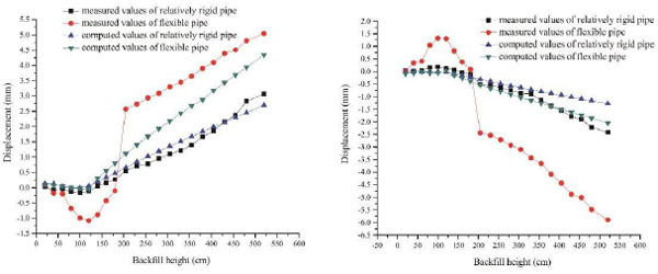
As is seen in Fig. (8), the crown of the pipes move upward first, and then the upward values decrease gradually until the pipes turn to deflection when the backfill covers over the crown of the pipe. When the backfill height is 100 cm (almost arrives the crown of the pipe), the measured values for relatively rigid pipe is -0.159mm, the maximum upwards value. At the same time, the measured crown value for flexible pipe reaches a maximum -1.08mm, 6.8 times larger than the relatively rigid pipe. For the point at the middle of the pipe, before the backfill covers the crown, the deformation of two pipes move inward gradually with the backfill height increases. After the backfill covers over the crown, the pipes began to move upwards.
The trends of the computed and measured values for both relatively rigid pipe and flexible pipe are basically the same. The values computed by FE model show an agreement with the measured values for the relatively rigid pipe. But for the flexible pipe, the measured values are much greater than the computed one. The reason is when the backfill height arrives 205cm, because of using clay for backfill and using machine to compaction, the bottom of the pipe has a sudden subsidence due to the nonlinear deformation of the soil. Therefore, it is hard to simulate the nonlinear large deformation of soil by the FE model.
Displacement comparison at the bottom of the pipe (D4) is shown in Fig. (9).
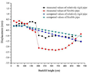
As is seen in Fig. (9), when the backfill height reached 205cm, a larger settlement emerges at the bottom of the pipe influenced by using clay for backfill as well as using scraper and compaction machine for construction. The measured displacement for flexible pipe is larger than that of the relatively rigid one before backfill height 430mm and afterwards, the displacements of flexible pipe start to move upward. This is because the measuring point is located near the end of the pipe and the pipe has a trend of tilting upward in axial direction.
The computed settlement of relatively rigid pipe is greater than the values of flexible pipe. The trends of the computed and measured values for relatively rigid pipe are basically the same. For flexible pipe, the computed and measured values have a larger difference. Except for the above reason that the FE model could not accurately simulate the nonlinear behavior of soil, neither could the 2D FE model simulate the deformation difference in different location along the axial direction in corrugated steel pipe culverts.
According to “Specification for Design and Construction of Corrugated Steel Pipe and Plate for Highway Bridges and Culverts (DB 15/T 654-2013) [15]”, the deformation of relatively rigid pipe is not more than 3%. And the deformation of flexible pipe is not more than 5%. In this paper, the tested largest deformation of relatively rigid pipe is 0.25%,and the largest deformation of flexible pipe is 0.42%, which are much less than standard requirements.
6.2. Comparative of Stress
The stresses in steel structure were calculated based on strains taking into consideration that the elastic modulus of steel is 206GPa. The measured values for layer 2,6,11 and 22 were chosen to be compared with the FEM computed values. Stress comparison is presented in Figs. (10 and 11). The negative values mean compression while the positive values mean tension.
As is shown in Figs. (10 and 11), the measured stresses at the crown of two pipes turn from positive to negative with increasing of backfill, which indicates that the stress at the crown of the pipes turn from tension to compression. Later, the crown compressive stresses measured in two pipes increase with the increasing of backfill. The measured values in the middle of two pipes are positive, which means that the locations of the points are in tension. The measured values at the bottom of the flexible pipe are smaller than the values in relatively rigid one during the initial backfilling. As the backfill height is increasing, the larger displacement in flexible pipe contributes to greater stress values in flexible pipe than the values in relatively rigid pipe.
On the analysis of the deformation result of above section, the deformation of flexible pipe is much greater than the relatively rigid pipe. But it is precisely because of the large deformation of flexible pipe, the soil arch effect is obvious. So the difference of the maximum stress between the flexible one and the relatively rigid one is not so much.
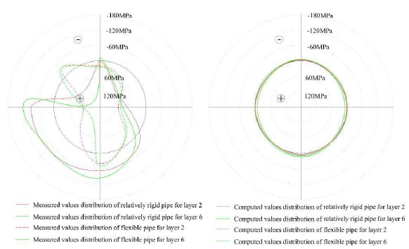
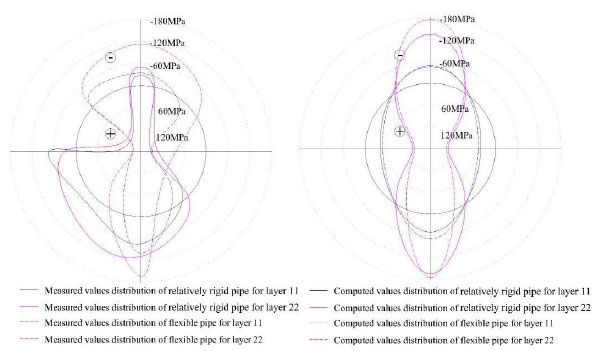
The distribution of stress calculated by FE model is symmetrical since the model is single pipe under symmetrical backfill. But actually there are effects between the two pipes which are located side by side. Moreover, FE model can not simulate the nonlinear of soil and combination of soil and structure. At the beginning of the backfill stage, due to the nonlinear of soil and structure-soil interaction is complex, the difference of computed values and measured values is obvious. But with the increase of filling height, soil and structure combines closely. After they bearing load jointly, the calculated values and measured values is gradually approaching the same.
6.3. Comparative of Earth Pressure
The measured vertical earth pressure values of the crown, middle of the pipes were chosen to be compared with the values computed by FE models and the soil column method (σv = γH). Vertical earth pressure comparison at the crown of the pipes (Number 5, 7 earth pressure measuring points) is shown in Fig. (12).
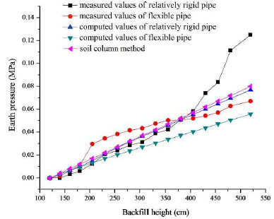
It can be seen from Fig. (11) that the measured values of flexible pipe are greater than the values of relatively rigid pipe when the backfill height is below 380 cm. From then on, the measured values of relatively rigid pipe are greater than the values of flexible one with the increasing of backfill. The computed values of relatively rigid pipe are always greater than that of flexible ones. In the beginning of backfill, the tendency of measured and computed values are in a good agreement. The measured values begin to be greater than the computed values as the backfill height increases. When backfilling is over, the measured value of flexible pipe is 0.067MPa. The measured value of relatively rigid pipe is 0.125MPa, 1.87 times larger than the flexible one.
When the backfill height is below 380 cm, measured earth pressures of flexible pipes are larger than the values of soil column method. As the increasing of backfill, the upper load of the flexible pipe is dispersed because of the forming of soil arching. The measured values of flexible pipe are less than the soil column method. Relatively rigid pipe owns larger stiffness and smaller deformation at the crown, so the soil arching could not form to share the upper load. As a result, the earth pressures of relatively rigid pipe are larger than values acquired by soil column method.
Horizontal earth pressure comparison in the middle of the pipes were chosen to be compared with the values computed by FE models and the soil column method (σH = K0γH , K0 = 1 - sinφ). Horizontal earth pressure comparison at the crown of the pipes (Number 2, 4 earth pressure measuring points) is shown in Fig. (13).
It can be seen from Fig. (13) that the measured and computed values of flexible pipe are larger than the values of relatively rigid pipe. As for relatively rigid pipe, the measured values are basically the same with the values calculated by soil column method, while the computed values are greater. As for flexible pipe, the measured values are in a close agreement with the values calculated by soil column method when the backfill height is below 280 cm. Then with the increasing of backfill, the measured values are greater than the values of soil column method due to the transverse deformation of the pipe, while the computed values are greater than that of the measured and soil column method ones. After the finishing of backfill, the measured value of relatively rigid pipe is 0.021MPa. The measured value of flexible pipe is 0.029MPa, 1.38 times larger than the relatively rigid one, which reflects the obvious soil and structure interaction.
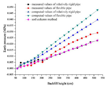
The larger deformation of the flexible pipe makes the interaction of soil and structure obvious, which reduces the vertical pressure of backfill soil on the structure. So the difference of the stress between relatively rigid and flexible pipe after the construction completion is not very big. Therefore during the design, it is supposed to choose the corrugation pattern and thickness of the corrugated plate with a consideration of practical situation in order to optimizing design and saving construction cost.
CONCLUSION
(1) The two culverts were both arched gradually with the increasing of backfill in the beginning. When the soil covered over the crown, the arching deformation began to fall and move to inside of the structure relative to the initial stage. As the backfilling was over, the displacement values of the crown and middle of the flexible pipe were twice of the relatively rigid ones. The stresses in both of the pipes were almost equal when the backfill finished. The crown earth pressure of relatively rigid pipe was 1.87 times than the value of flexible pipe.
(2) At the beginning of the backfill stage, due to the nonlinearity of soil and the complexity of soil-structure interaction, the FE simulation results cannot reflect the stress state of the structure veritably. But with the increase of filling height, soil and structure combine closely. After sharing the upper pressure together, the FEM could basically reflect the stress state of the structure.
(3) The larger deformation of the flexible pipe makes the interaction of soil and structure obvious, which reduces the vertical pressure of backfill soil on the structure. It is supposed to choose the corrugation pattern and thickness of the corrugated plate with a consideration of practical situation in order to optimizing design and saving construction cost.
NOTATIONS
The following symbols are used in this paper:
| Ap | = Area; |
| D | = Depth of sinusoidal corrugations; |
| H | = Height of soil column; |
| Ip | = Moment of inertia; |
| K0 | = Coefficient of earth pressure at rest; |
| P | = Pitch of sinusoidal corrugations; |
| t | = Plate thickness; |
| γ | = Unit weight of soil; |
| σH | = Horizontal earth pressure; |
| σv | = Vertical earth pressure; |
| φ | = Angle of internal friction. |
CONFLICT OF INTEREST
The authors confirm that this article content has no conflict of interest.
ACKNOWLEDGEMENTS
This research project is supported by the Transportation Science and Technology Plan of Shandong Province (2015 B31).


