All published articles of this journal are available on ScienceDirect.

Numerical Simulation Research of Construction Method for Shallow Buried Large Section Tunnel
Abstract
The background of this paper is based on Deli tunnel of Xi’an to Chengdu Railway passenger dedicated line. In order to compare and optimize this large section tunnel project under different construction methods, General FEA software ANSYS was utilized to simulate and analyze the stress and deformation in 2-D and 3-D. According to the Deli tunnel engineering case, the preliminary comparison and discussion of mechanical properties and deformation characteristics of the construction of bench cut method and two side-wall pilot tunnel method have been carried out. From this simulation, we made the conclusion for different mechanical properties and deformation characteristics in different construction methods. It shows that the two side-wall pilot tunnel method results in less stress and deformation than the bench cut method. Therefore, it is safer to use the former method. The key step for bench cut method is the upper excavation, and the key step for two side-wall pilot tunnel method is the upper core soil excavation. Monitoring and enhanced support of these key areas is imperative to guarantee the smooth construction.
1. INTRODUCTION
Railway is an important and basic transportation facility in China which plays an important role in transportation system. The tunnel with super large section and long span has the characteristics of large sectional area and long span, which is a type of tunnel developed with the construction of multi-track high-speed railway in recent years [1].
Although a lot of large section and long span tunnels have so far been built across the country, tunnels with super large section can only be seen in station tunnels, which have a large cross section of construction. Difficulty arises in construction of these tunnels due to complex mechanical property of tunnel and surrounding rocks, and it is associated closely to its stress and deformation. In a uniform stress system, it is known that structures are supported by surrounding rocks, as they bind each other and function together. To date, deformation and stability research of super large section tunnel have been focusing on numerical simulation, model test and field investigation of construction method, where the numerical simulation of tunnel construction is a very effective method to study such problems [2-7]. Since the problem only appears for a short time, design and construction of tunnels with super large section have so far gained very little experience to be used as references and there are a lot of challenges to overcome. In particular, for the construction of tunnels with super large section and long span for high-speed railway passenger dedicated line, there has been no new achievement in research of surrounding rock deformation.
Yang Jianhua [8], Liu Deping [9] and Yu Cunpeng [10] have made numerical simulation researches on weak surrounding rocks and concluded that stress concentration occurs at the bottom of the surrounding rocks beneath the wall in the whole construction process. Cao Tailin [11] has performed a comparative study using various construction methods with engineering practice and obtained the best solutions of two side-wall pilot tunnel method in some constructions. Wang Zhideng [12] has analyzed the section of Qianhuang tunnel beneath Ningbo-Taizhou-Wenzhou Expressway by 3-D finite element method, and their result indicates that excavation with large pipe-shed advanced support and two side-wall tunnel method has a good control of pavement and tunnel vault settlement; meanwhile, because vault settlement and horizontal convergence displacement are greatly impacted by longitudinal excavation spatial effect and covering thickness, computational results provide some theoretical basis for design and construction of railway tunnel. Super large section tunnel involves a lot of construction procedures and at present many studies analyze each procedure for the optimization of constructions scheme, For example, adjusting the cross section of pilot tunnel can take advantage of mechanical equipment and improve construction progress, and rationally designed core soil thickness is capable of changing the stress condition of tunnel properly and improve the stability of surrounding rocks during construction.
At present, few large span railway tunnels have been built in China. For example, New Nail Bay tunnel of Xiangyang-Chongqing railway Line II has a maximum span of 22m and a maximum excavation area of 250.36m2; Dageshan highway tunnel in Guizhou Province has an excavation width and height of 22m and 13m, respectively. However, the Deli tunnel as studied in this article has a maximum excavation section of 302.52m2 and a maximum excavation height of 15.37m, which is unprecedented, given the large span and cross section. For super large section and long span tunnels, construction of two side-wall pilot tunnel method can have a good control of the deformation of surrounding rock. During construction of super large section and long span tunnels, excavation of tunnel face causes great effect on surrounding rock deformation and is a major point of control during construction. This article emphasizes the influence of tunnel excavation on surrounding rock deformation, and provides the experience and reference for design and construction of super large section and long span tunnels.
Long span tunnels always have a long excavation span, complex construction procedures, repetitious disturbances on surrounding rocks and complex soiling loading, real-time monitoring and feedback of surrounding rock-lining deformation and stress are particularly crucial for controlling the stability of long span tunnel. Therefore, researches should be made on lining mechanics analysis and surrounding rock deformation mechanism before construction so as to adopt appropriate excavation sequence and supporting scheme and to ensure safety and controllability of construction [13]. Based on engineering geological condition of Deli tunnel, this article compares and discusses the construction of bench cut method and two side-wall pilot tunnel method by large universal finite element software ANSYS, which provides a computational support for the establishment of scientific construction schemes.
2. PROJECT CASE
2.1. Project Profile
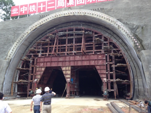
Deli tunnel, west section of Xi’an-Chengdu railway passenger dedicated line, has an entrance section of 7, 837m, where section DK144+663-DK144+865 is a widened section of station throat entering tunnel and is characterized by long span and low buried depth. There are four different types of cross sections within 202m of this section, where a type B grade V section (with an excavation clearance of 20.7m × 14.51m) of long span surrounding rock (59m long) was selected in section DK144+696-DK144+755 for this computation. See Fig. (1) for condition of construction site.
Main lithology of Deli tunnel is expansive soil, fine thick pellet soil, gravelly soil and mass rock soil of quaternary system, metamorphic rocks, magmatic rocks such as granite and diorite as well as tectonites such as cataclasite distributed in fault zone. Tunnel area is located in South Qinling tectonic zone that is surrounded by Shang-Dan fault zone and Mianlue-Bashan arc-shaped fault zone. This area is characterized by complex geological structure and developed intraformational folding. Surface water is composed of mainly river water and ditchwater, where rivers have running water all year around and water volume increases significantly during the rainy season. Underground water is mainly karstic water from bedrock fracture. Underground water in tunnel area is a typical infiltration-runoff circulatory system mainly replenished by atmospheric precipitation and above-ground ditch water.
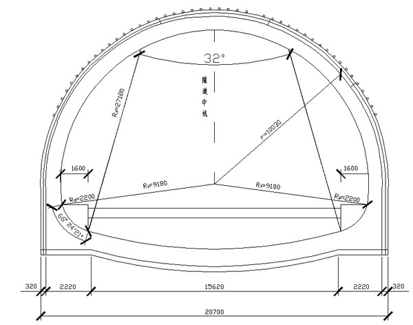
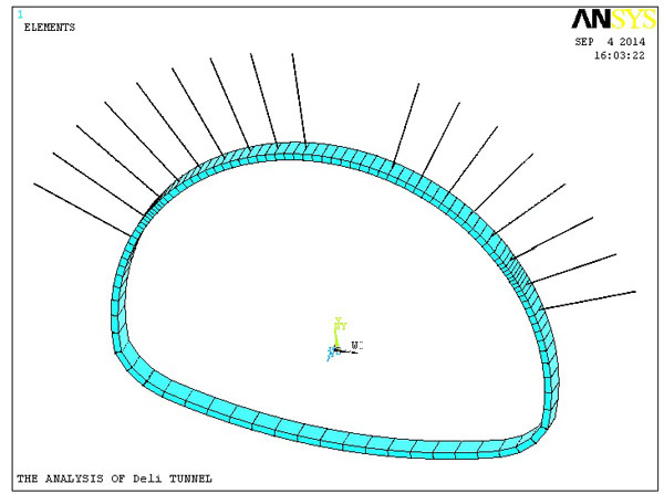
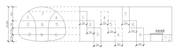
See Fig. (2) for simulated construction drawing of cross section selected in this article; see Table 1 for parameters of support.
| Supporting structure parameters | ||
|---|---|---|
| Concrete spraying | Position | Whole section |
| Thickness | 32cm | |
| Bar-mat reinforcement | Position | Arch wall |
| Specification | φ8 | |
| Spacing | 20×20 cm | |
| Bolt | Position | Arch wall |
| Length | 5m | |
| Spacing | 0.8×0.8 cm | |
| Steel frame | Position | Total annular |
| Type | I25a shape steel | |
| Spacing | 0.5m | |
2.2. Overview of Primary Construction Method
At present, railway passenger dedicated lines developed domestically are mainly double-track railways constructed in one stage. Space for engineering technological operation, interior parts, safety and rescue paths as well as aerodynamics effect are also taken into consideration. Tunnels have a sectional area of more than 150m2 and belong to large or super large section tunnels. Throat section at entrance of Deli tunnel in this project has a super large section, existing construction technique and specific tunnel shape need to be considered in the selection of construction method for super large section tunnel, so as to determine the sequence of excavation, and prevent loosening of rock mass and optimize closure time of cross section on the basis of tunnel shape.
Large section tunnels are mostly excavated by steps and the main construction methods include advanced short-bench step method for top-half cross section, middle wall method, unilateral pilot tunnel method, two side-wall pilot tunnel method and tunnel-column method and wall opening method. Although, there are various excavation methods for super long span tunnels, the most basic ones are appropriate pre-reinforcement treatment of stratum combined with two side-wall pilot tunnel method, CD or CRD method, bench cut tunnel method or combination of any the above methods. The main thought is to turn big issues into small one, arch first lining method or side wall first lining method by virtue of auxiliary construction method, so as to form a closed or semi-closed bearing structure along excavation outline as early as possible and then to excavate core soil and inverted arch.
This article compares the working conditions of construction by three-bench seven-step excavation method and two side-wall pilot tunnel method, taking into consideration studies on basic construction method of tunnel and investigation of project case, combined with application of the new Austrian tunneling method and actual situation of the project on site. For the purpose of unified computing, same materials are used in primary support; please see Table 1 for detailed parameters of supporting structure.
2.2.1. Two Side-wall Pilot Tunneling Method
Excavated section of two side-wall pilot tunnel method is shown in Fig. (3).
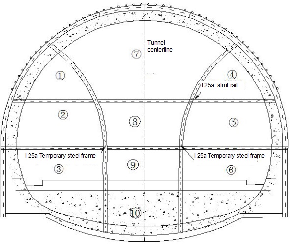
Construction procedures: a. Excavate part  by manpower air pick (weak blast can be used as necessary). b. Construct the primary and temporary supports around pilot tunnel in part . c. Excavate Part
  by manpower air pick ; Part and Part shall be kept with a distance of 3-5cm. d. Construct the primary and temporary supports around pilot tunnel in Part. e. Excavate Part
  ,
,  and
and  in sequence and erect primary and temporary supports around pilot tunnel with the same construction method mentioned above. f. Excavate Part
  and erect steel frame for arch part and primary support of construction. g. Construct Part
  and
and  by two-bench method, close the steel frame erected at bottom of pilot tunnel into ring form and spray concrete up to design thickness.
2.2.2. Construction of Three-bench Seven-step Excavation Method
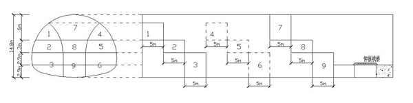
Excavated section of bench cut method is as shown in Fig. (4).
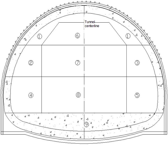
Construction procedures: a. Firstly, excavate the upper bench Part and erect primary support for upper tunnel structure after excavation. b. After upper bench is constructed to 1-3m, excavate the left side Part of middle bench, construct the primary support for bench structure in left tunnel, with supporting structure the same as that of Part . c. After Part is constructed to 1-3m, excavate the right side Part  of middle bench and construct the primary support for bench structure in right tunnel. d. After Part is constructed to 1-3m, construct Part and of lower bench in accordance with the construction method for Part and . e. Then core soil Part , and can be excavated and kept a step distance of 1-3m from upper, middle and lower benches. f. Finally, inverted arc Part is excavated, and service road can be built in the middle for convenience of mechanical slag discharge and other constructions.
3. 2-D NUMERICAL COMPUTATION AND RESULT ANALYSIS
3.1. Modeling
This computation is based on the project background of Deli tunnel in Xi’an-Chengdu railway passenger dedicated line, which carries out a 2-D numerical simulation analysis for the process of construction with two side-wall pilot tunnel method and three-bench seven-step method using means of large universal finite element software. Three elements were used in this computation – solid element (Plane42) for simulation of surrounding rocks, beam element (Beam3) for simulation of sprayed concrete and steel arch and link element (Link1) for simulation of bolt. Bending rigidity of steel arch was also considered in computation, which allows for an excellent support for surrounding rock after tunnel excavation. In this model, surrounding rock adopts solid element Plane42, uses elastic-plastic DP constitutive model and its structure uses linear elastic constitutive model. See Fig. (5) for model of primary support and see Table 2, for material property of computing elements.
Contact problem is a highly nonlinear behavior. Surface - surface contact analyses were used in this project. After building the tunnel model, the target elements and contact elements were defined, which moved together with the tunnel structure linked by a common real constant.
During finite element computation, boundary conditions show great impact on result. In order to decrease the adverse impact of boundary conditions on result as much as possible, and ordinarily, the deformation of surrounding rock impacted by excavation is 3 to 5 times of the span, the length selected in this computation model is 4 times of tunnel span and depth boundary selected is 3 times of tunnel height. The tunnel has a buried depth of 22m, height of 14.5m and span of 20.7m, and as a result, the established model boundary has a total length of 185.66m and a total height of 80m. Boundary conditions of computational model are vertical constraints for bottom surface, free boundary for upper boundary and horizontal restraints for left and right boundaries.
| Material | Surrounding rock | Bolt | C30 concrete |
|---|---|---|---|
| Density (kg/m3) |
2000 | 7959 | 2500 |
| Elasticity modulus (Pa) |
1.00E+09 | 1.70E+11 | 3.00E+10 |
| Poisson ratio | 0.4 | 0.3 | 0.2 |
| Frictional angle (°) |
28 | - | - |
| Cohesion (kPa) |
100 | - | - |
3.2. Displacement Analysis
3.2.1. Displacement Analysis for Two Side-wall Pilot Tunnel Method
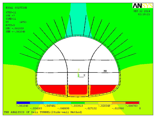
The data from Fig. (6) displacement deformation for two side-wall pilot tunneling method indicates that:
1) Vault has a large settlement, and a maximum settlement during excavation of upper core soil. Relative settlement value is 6.636mm after deducting stratum settlement under initial displacement from final step, indicating that vault will have a large settlement after the support of rock mass is completely removed.
2) Horizontal displacement at vault is 0.712mm; and horizontal displacement at haunch and arch springing is 2.143mm, both towards the inside direction. This is because, after support of vault is completely removed, upper load is completely assumed by the arch formed by excavation and haunch bears a large pressure; and horizontal displacement towards the inside of tunnel occurs.
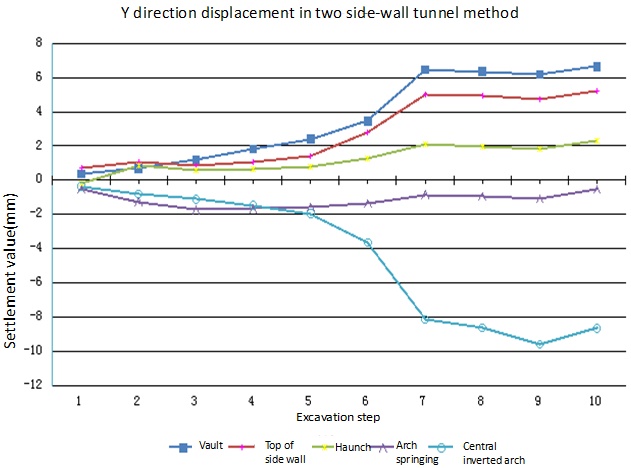
3) As shown in Fig. (7), in Step 7 of core soil excavation, vault begins to have a large settlement deformation; meanwhile, arch springing has a large displacement deformation in Y direction that is shown as arching up. Additional stress resulted from unloading contributes to its arching up. It can be observed that excavation of top soil at upper part had a great impact on displacement of each feature key-point, so support in time is needed during tunnel excavation.
3.2.2. Displacement Analysis for Bench Cut Method
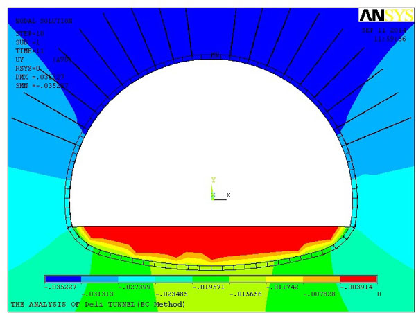
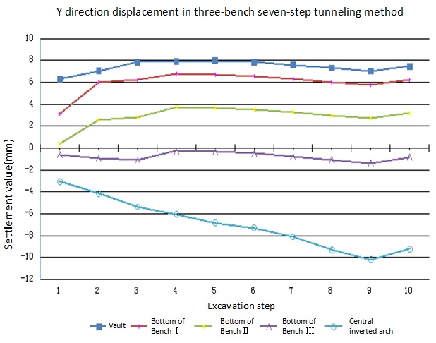
It can be seen from displacement deformation in Y direction in Figs. (8 and 9) that:
1) In bench cut tunneling method, vault has a large settlement, with the maximum settlement happening during excavation of upper core soil. Relative settlement value is 7.448mm after deducting stratum settlement under initial displacement from final step. These results indicate that vault will have a large settlement after support of rock mass is completely removed. Magnitude of deformation is 0.812mm larger than that in two side-wall pilot tunnel method, and so does the area with large deformation in comparison to the two side-wall pilot tunnel method. Furthermore, settlement value at haunch and arch springing is 0.872mm larger than that in two side-wall pilot tunnel method, indicating that bench cut method performs less well when compared to the two side-wall pilot tunnel method in settlement control.
2) In bench cut tunneling method, Y direction displacement at arch springing increases with excavation of core soil. This indicates that inverted arch pouring will be good for deformation control at arch springing, as inverted arch structure can transmit the formation pressure at upper tunnel to ground floor through side wall structure of tunnel and effectively resist the stratum counter-force transmitted from bottom tunnel. As a result, it can increase the structural stability after concrete pouring.
According to the requirement for relative subsidence of tunnel vault of grade V surrounding rock and at a buried depth of more than 50m,specified in Railway Tunnel Construction Specifications [14], the ultimate relative displacement (%)for primary support of double-track tunnel is 0.08-0.16%. This project requires a settlement of 11.6mm-23.2mm, so both two side-wall pilot tunnel method and bench cut method meet the requirements of the specifications.
From the comparison between Figs. (7 and 9), it can be seen that two side-wall pilot tunnel method has a settlement of about 2 to 4mm during side wall excavation, despite having a large settlement up to 10mm during core soil excavation; whereas bench cut method has a large settlement from 6 to 8 mm at the beginning of excavation and the settlement value increases slowly with tunnel excavation.
As indicated above, bench cut tunneling method has a poor control of deformation of large section tunnel; while two side-wall pilot tunneling method has a good control of surrounding rock deformation; inverted arch erected at the bottom of tunnel greatly help for tunnel stability.
3.3. Stress Analysis
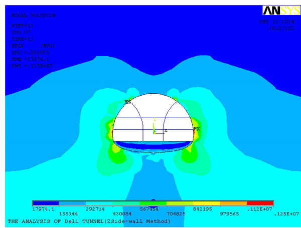
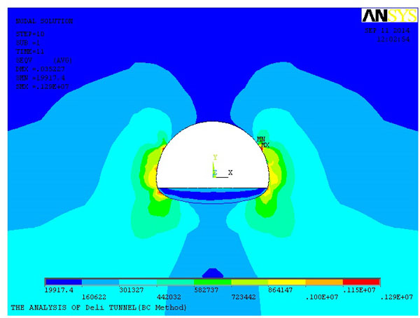
3.3.1. Equivalent Stress Analysis
As shown in the equivalent stress diagram for two side-wall pilot tunneling method Fig. (10) and equivalent stress diagram for bench cut tunneling method Fig. (11), the maximum soil stress after excavation by two side-wall pilot tunnel method occurs at top of two side walls and arch springing at both sides have a maximum stress of 1.25MPa. This figure is due to function of supporting structure because steel arch support contributes a lot to tunnel stability. However, the maximum soil stress after excavation by bench cut method occurs at the central part, right above the vault and arch springing at both sides that have a maximum stress of 1.29Mpa. Bench cut tunneling method has a larger stress than that of two side-wall pilot tunneling method, so does the area with a larger stress.
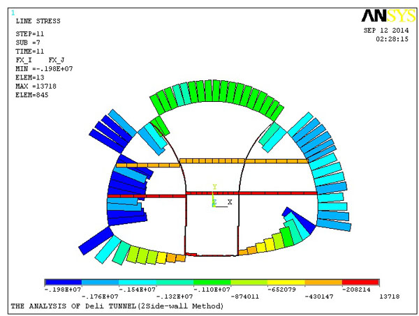
3.3.2. Axial Force Analysis for Supporting Structure
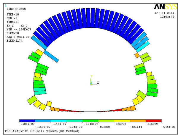
As shown in axial force diagrams of Figs. (12 and 13) (axial force shown in the figure is only numerical value), after excavation by two side-wall pilot tunnel method, the maximum stress of steel arch support and sprayed concrete occurs at the middle-upper part of left arch buttress that has a maximum axial force of 198KN. During construction using two side-wall pilot tunneling method, axial force of first lining at left excavation is larger than that of right excavation, which has a lot to do with excavation steps. The results indicate that first excavation releases a greater ground stress and thus first lining bears a larger axial stress. Therefore, monitoring and measurement should be strengthened during construction. After excavation by bench cut method, the maximum stress event of steel arch support and sprayed concrete occurs at vault of Bench I, has a maximum axial force of 186KN. During construction using bench cut tunneling method, vault deformation should be specially noticed during construction of Bench I and support can be used as necessary. Stress of steel arch in bench cut method is 11KN smaller than that of steel arch support and sprayed concrete in two side-wall pilot tunnel method.
3.3.3. Axial Force Analysis for Bolt
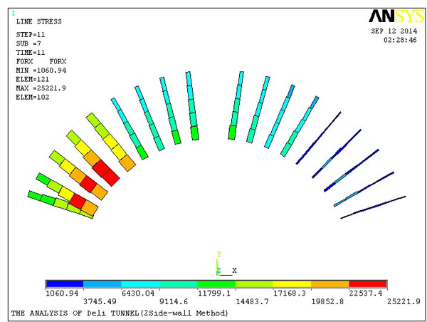
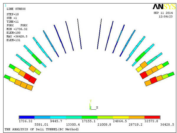
As shown in bolt axial force diagrams of Figs. (14 and 15), after excavation by two side-wall pilot tunnel method, left excavation exhibits a maximum bolt axial force of 25.221KN, indicating that first excavation releases a greater ground stress and bolt bears a larger tensile force. Monitoring and measurement should be strengthened during construction as a result. The right excavation is shown to have a relatively smaller bolt axial force, indicating that two side-wall pilot tunneling method has a good control of stress on tunnel surrounding rocks. After excavation by bench cut method, maximum bolt axial force occurs at left and right side of Bench II that has a maximum axial force of 36.428KN, indicating that tunnel wall may have an X-direction displacement towards inside tunnel, so monitoring and measurement should be strengthened during construction.
4. COMPREHENSIVE COMPARISON OF CONSTRUCTION SCHEMES
Based on the results of analysis and numerical computation of two construction schemes, comprehensive comparison for advantages and disadvantages of both construction schemes are shown in Table 3.
| Construction method | Bench cut tunneling method by steps | Two side-wall pilot tunnel method |
|---|---|---|
| Settlement control | Common | Good |
| Settlement/mm | 7.448 | 6.636 |
| Construction period | Short | Long |
| Amount of primary support | Small | Large |
| Stress of primary support/KN | 186 | 198 |
| Cost | Low | High |
Two side-wall pilot tunneling method has a smaller settlement than bench cut method by steps as can be seen from the computed result of displacement. It is due to that i) the former has more construction procedures and thus stress can be unloaded by steps to avoid too much stress released at one time; ii) it ensures the stability of surrounding rock itself and iii) concurrently, temporary strut rail and support in two side-wall pilot tunnel method is helpful for tunnel stability. The disadvantage of the two side-wall pilot tunneling method (in comparison to the bench cut method) is that, stress of primary support is larger, and excavation of next cycle can only be started when concrete is up to the compressive strength specified in requirement of specifications during erection of primary support. This should be given enough attention during construction.
Based on the result of numerical computation, both two side-wall pilot tunnel method and three-bench seven-step tunneling method have a good deformation control of super large section tunnel, and the control level is within the range of requirement of specifications. Two side-wall pilot tunnel method has a better stress-strain control than bench cut method.
Combing the result of comprehensive numerical analysis and taken into consideration for economy and timeliness of tunnel engineering construction, two side-wall pilot tunnel method is recommended to be used for site construction of Deli tunnel.
5. 3-D NUMERICAL COMPUTATION AND RESULT ANALYSIS
2-D numerical simulation is limited by the fact that it cannot effectively reflect the time and spatial effect of rock-soil mass during construction of tunnel engineering [15]. In actual analysis, 2-D numerical simulation can effectively simulate the stress-strain of supporting structure, but for excavation by steps, 2-D numerical simulation cannot reflect the drilling footage and mutual effect between soil mass and supporting structure during excavation. In previous computation, excavation of each step is only the similar operation on elements corresponding to 2-D model; in actual tunnel excavation, when upper tunnel face is carried forward, lower surrounding rock is still not excavated, 2-D model cannot effectively reflect the relationship between tunnel face and footage. Furthermore, 2-D numerical simulation cannot simulate different step distances of the same construction method, so 3-D numerical simulation models are needed to be established for computation so as to analyze the stress and strain of tunneling in different step distances of construction [16].
In this 3-D numerical simulation computation, a numerical simulation is made on section DK144+733-DK144+734 of Deli tunnel for two side-wall pilot tunneling method by steps. Like 2-D numerical simulation, the computation is performed on two working conditions. The first working condition has an excavation step distance of 3m and space between left and right pilot tunnels of 6m Fig. (16); the second working condition has an excavation step distance of 5m and space between left and right pilot tunnels of 15m (Fig. 17).
5.1. Modeling
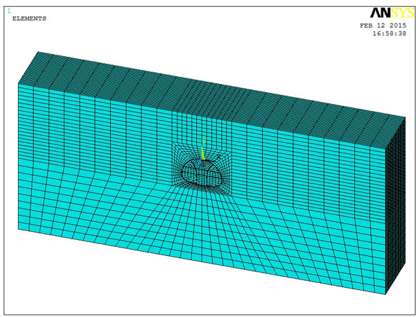
A 3-D finite element model is established on the basis of stratum-structure continuum, according to construction conditions on site. In finite element computation, boundary conditions have great impact on result. In order to decrease the impact of boundary conditions on result as much as possible, length boundary selected in this computation models is 4 times of tunnel span and depth boundary selected is 3 times of tunnel height. The tunnel has the same buried depth as DK144+733 cross section that is about 24m, has a height of 14.75m and a span of 20.7m, so the established model boundary has a total length of 185.66m and a total height of 82m.
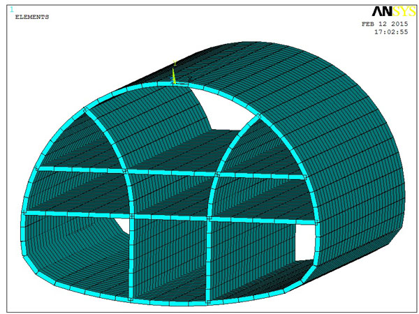
Modeling length of two side-wall pilot tunnel method was selected as 30m, and boundary conditions of computational model are vertical constraints for bottom surface, free boundary for upper boundary and horizontal restraints for left and right boundaries. See Figs. (18 and 19) for finite element physical models of two side-wall pilot tunnel method.
5.2. Finite Element Simulation for the Construction Process of Two Side-wall Pilot Tunnel Method
Finite element simulation for the construction of two side-wall pilot tunnel method can be divided into the following steps:
- Apply a gravity stress, calculate and get gravitational stress field;
- Excavate the upper part,middle part and lower part of left pilot tunnel, erect primary support and temporary strut rail, and make simulation computation;
- Excavate the upper part,middle part and lower part of right pilot tunnel, erect primary support and temporary strut rail, and make simulation computation;
- Excavate the upper part,middle part and lower part of core soil, erect temporary strut rail and make simulation computation;
- Demolish the temporary support of cross section of which excavation has been completed, pour concrete of inverted arch and make simulation computation.
Here, drilling and excavation of different benches are run simultaneously. Simulation uses excavation method of simultaneous drilling. See Fig. (20) for schematic diagram of detailed construction procedures.
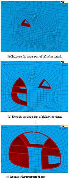
- a. Excavate the upper part of left pilot tunnel.
- b. Excavate the upper part of right pilot tunnel.
- c. Excavate the upper part of core soil.
- d. Demolish temporary support and pour inverted arch.
5.3. Displacement Analysis
5.3.1. Displacement Analysis for Two Side-wall Pilot Tunnel Method with a Step Distance of 3m
Development process of UY direction displacement of tunnel in two side-wall pilot tunnel method with a step distance of 3m is shown in Fig. (21).
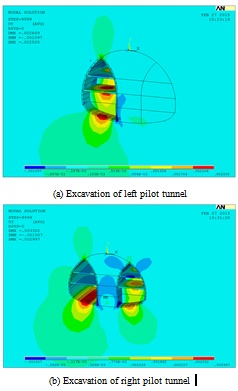
- a. Excavation of left pilot tunnel
- b. Excavation of right pilot tunnel
- c. Excavation of core soil
- d. Pouring of inverted arch
It can be observed that the two side-wall pilot tunnel method shows the following phenomena after excavation:
- In the first and second steps of excavating left pilot tunnel, vertical displacement of tunnel occurs mainly at middle and lower part of arch buttress; tunnel excavation will result in ground heave on the bottom, and strut rail provides some support to the tunnel. Displacement changes of side wall should be paid enough attention during excavation of left and right pilot tunnel.
- After left pilot tunnel is excavated into ring form, right lower lining of left pilot tunnel has a large deformation at the interaction of right angle; meanwhile, left lower part of left pilot tunnel does not have large deformation; same results can be seen after right pilot tunnel is excavated, indicating that erection of arch springing into an arched supporting structure is helpful for the stability of excavation face.
- During excavation of core soil in the central tunnel, steel arch support of vault and at lower part of vault will have great deformation, which indicates that excavation of core soil is a key point of two side-wall pilot tunneling method. At this moment, support is required to be strengthened.
- When temporary steel frame of the excavation face that has been closed into a ring form is demolished, deformation range of vault extends, indicating that demolishment of temporary support has certain impact on deformation of vault. Pouring of inverted arch has an effective control of ground heave of tunnel and UY direction displacement of vault decreases after pouring, so pouring of inverted arch is helpful for the stability of supporting structure.
After completion of excavating the first cross section, UY direction displacement of the profile sectioned by axis of top left pilot tunnel, top tunnel vault and top right pilot tunnel, as section line, is shown in Fig. (22).
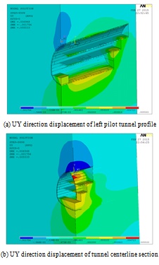
- a. UY direction displacement of left pilot tunnel profile
- b. UY direction displacement of tunnel centerline section
- c. UY direction displacement of right pilot tunnel profile
See Table 4 for maximum and minimum surrounding rock displacement of the tunnel during each excavation step, in which positive value means ground heave and negative value indicates tunnel settlement.
| Excavation step | MAX (mm) | Position | MIN (mm) | Position |
|---|---|---|---|---|
| 1 | 1.87 | Bottom of left pilot tunnel | -0.74 | Left and right side wall of left pilot tunnel |
| 2 | 2.57 | Bottom of left pilot tunnel | -0.80 | Middle part of left side wall and bottom of right side wall in left pilot tunnel |
| 3 | 2.50 | Core soil in middle part of left pilot tunnel | -1.09 | Bottom of right side wall in left pilot tunnel |
| 4 | 2.73 | Bottom of left pilot tunnel | -1.15 | Bottom of right side wall in left pilot tunnel |
| 5 | 2.89 | Bottom of left pilot tunnel | -1.11 | Bottom of right side wall in left pilot tunnel |
| 6 | 2.99 | Bottom of left pilot tunnel | -1.01 | Bottom of right side wall in left pilot tunnel |
| 7 | 3.26 | Bottom of left pilot tunnel | -1.15 | Tunnel vault |
| 8 | 3.38 | Bottom of left pilot tunnel | -1.57 | Tunnel vault |
| 9 | 3.38 | Bottom of left pilot tunnel | -1.80 | Tunnel vault |
| 10 | 3.91 | Inverted arch | -1.75 | Tunnel vault |
5.3.2. Displacement Analysis for Two Side-wall Pilot Tunnel Method with a Step Distance of 5m
Development process and rules of UY direction displacement for two side-wall pilot tunnel method with a step distance of 5m is the same as that of working condition I. See Table 5 for maximum and minimum surrounding rock displacement of the tunnel during each excavation step, where positive values indicate ground heave and negative values indicate tunnel settlement.
| Excavation step | MAX(m) | Position | MIN (mm) |
Position |
|---|---|---|---|---|
| 1 | 2.08 | Bottom of left pilot tunnel | -0.82 | Left and right side wall of left pilot tunnel |
| 2 | 2.90 | Bottom of left pilot tunnel | -1.08 | Middle part of left side wall and bottom of right side wall in left pilot tunnel |
| 3 | 2.85 | Core soil in middle part of left pilot tunnel | -1.15 | Bottom of right side wall in left pilot tunnel |
| 4 | 2.92 | Bottom of left pilot tunnel | -1.11 | Bottom of right side wall in left pilot tunnel |
| 5 | 3.07 | Bottom of left pilot tunnel | -1.12 | Bottom of right side wall in left pilot tunnel |
| 6 | 3.18 | Bottom of left pilot tunnel | -0.89 | Bottom of right side wall in left pilot tunnel |
| 7 | 3.16 | Bottom of left pilot tunnel | -1.35 | Tunnel vault |
| 8 | 3.67 | Bottom of left pilot tunnel | -1.77 | Tunnel vault |
| 9 | 4.21 | Bottom of left pilot tunnel | -1.93 | Tunnel vault |
| 10 | 4.84 | Inverted arch | -1.99 | Tunnel vault |
Under the working condition of two side-wall pilot tunnel method with a step distance of 5m, the rock-soil area shows settlement larger than that with a step distance of 3m, total settlement is relatively large and settlement range has expanded to earth’s surface, which are not discovered in the same excavation cycle under working condition I, so the step distance of 3m is suitable for two side-wall pilot tunneling method.
5.4. Stress Analysis
Surrounding rock is a type of elasto-plastic material; and stress on surrounding rock of tunnel changes most significantly with tunnel excavation, plastic deformation occurs, when variation of stress on surrounding rock around the tunnel exceeds the elastic limits of rocks.
5.4.1. Displacement Analysis for Two Side-wall Pilot Tunnel Method with a Step Distance of 3m
Cloud diagram for equivalent stress changes of two side-wall pilot tunnel method with a step distance of 3m is shown in Fig. (23). From computed result, it can be seen that after the excavation of Bench I of left pilot tunnel, major principal stress at both side walls of left pilot tunnel changes a lot, an area of stress concentration appears at side wall and an area of tensile stress concentration occurs at vault of Bench I that has a maximum tensile stress of 0.52MPa; at bottom of the Bench I, there is a large area of compressive stress concentration that has a maximum compressive stress 0.13MPa. As excavation of left pilot tunnel goes on, major principal stress has little change, mainly located at vault, top and bottom of side wall. After Bench III of left pilot tunnel is excavated, a large compressive stress concentration area appears at bottom of right side wall in left pilot tunnel that has a maximum compressive stress of 1.2MPa. This result is consistent with the result of deformation computation, which indicates that the stability of the bottom of right side wall is most likely to be lost and requires to be strengthened with support.
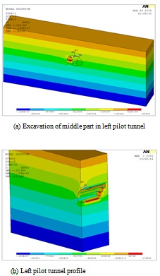
(a) Excavation of middle part in left pilot tunnel
(b) Left pilot tunnel profile
5.4.2. Displacement Analysis for Two Side-wall Pilot Tunnel Method with a Step Distance of 5m
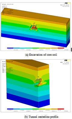
Cloud diagram for equivalent stress changes of two side-wall pilot tunnel method with a step distance of 5m is shown in Fig. (24). From computed result, it can be seen that as excavation of core soil goes on, and changes in distribution of major principal stress is obvious. Furthermore, compressive stress has also shown a significant change at vault with a compressive stress of 0.27Mpa. After excavation of core soil, given the excavation and pouring of inverted arch, compressive stress at vault is reduced to 0.23Mpa and tensile stress at inverted arch is reduced to 0.17Mpa. This indicates that pouring of inverted arch and closure of tunnel section is helpful for stability of surrounding rocks.
According to the computed results of displacement and stress under two working conditions, it can be seen that either stress of lining or tunnel deformation at a step distance of 5m is significantly larger than the computed result at a step distance of 3m. Therefore, two side-wall pilot tunnel method with a step distance of 3m is recommended for this tunnel construction.
- a. Excavation of core soil
- b. Tunnel centerline profile
CONCLUSION
ANSYS was used in this study for numerical simulation of super large section tunnel (Deli tunnel of Xi’an-Chengdu railway passenger dedicated line, with a sectional area of 302.52m2) constructed by steps, and for stress and deformation analysis of tunnel lining under working conditions of bench cut method and two side-wall pilot tunnel method. Results of the simulation show that:
- In bench cut tunneling method, settlement at vault is 7.448mm and is 0.812mm larger than that of two side-wall pilot tunnel method; settlement at haunch and arch springing is 0.872mm larger than that of two side-wall pilot tunnel method. Therefore, bench cut tunnel method is not as well performed compared to two side-wall pilot tunnel method in settlement control.
- After excavation by bench cut method, steel arch has shown a maximum axial force of 186KN, 11kN smaller than that of two side-wall pilot tunnel method; and at the same time, bolt has a maximum axial force of 36.42kN that is 11.20kN smaller than of two side-wall pilot tunnel method.
- Stress on primary support using two side-wall pilot tunneling method is larger than that of bench cut method; excavation of next cycle only can be started when concrete is up to the compressive strength specified in requirement of specifications during erection of primary support, which needs to be specially inspected during construction. Meanwhile, monitoring and measurements should be strengthened at tunnel vault and in-time support is also required to ensure smoothness of construction.
- Combing the result of comprehensive numerical analysis together with consideration for economy and timeliness of tunnel engineering construction, two side-wall pilot tunnel method with a construction step distance of 3m is recommended to be used for construction of Deli tunnel.
CONFLICT OF INTEREST
The authors confirm that this article content has no conflict of interest.
ACKNOWLEDGEMENTS
This paper was supported by the Natural Science Foundation of Shaanxi Province (2016JM4014)and the National Natural Science Foundation of China (41402265, 51508462). The useful help of students Ge Li in the calculations is highly appreciated.

