All published articles of this journal are available on ScienceDirect.

Investigation on the Flexural Behavior of Corroded Concrete Beams Repaired by CFRP Sheet Under Different Corrosion Levels
Authors Info & Affiliations
Abstract
The paper presents an investigation on the flexural behavior of corroded reinforced concrete (RC) beam strengthened with Carbon Fiber Reinforced Polymer (CFRP) sheets. Different levels of corrosion are considered as a new method for classifying the corrosion levels of the corroded RC members. Twenty RC beams with five corrosion levels were fabricated by accelerated corrosion equipment, and then the CFRP were used to strengthen these members, considering the effect of different CFRP layers and different strengthened schemes, finally the static flexural load test was carried out. The test results show that the bearing capacity of the CFRP strengthening corroded RC beams is effectively enhanced, the crack width is restrained, and the flexural stiffness is improved. The ultimate flexural capacity of the specimens strengthened by one layer of CFRP sheet raises by 30% to 50% than that of the unstrengthened ones, with the increase of the corrosion level, the enhancement decreased. With the increase of the number of CFRP layers, the bearing capacity increases, while the increasing ratio reduces with the increase in the number of layers. For specimens with obvious cracks, the effectiveness of the strengthening method by bonding CFRP after cutting or chiseling off concrete method (RM1 or RM2) is higher than the method of bonding CFRP directly (DM). It is suggested that the corroded RC members with Level A, B or C1 can be strengthened by DM, while the other level members should be strengthened by RM1 or RM2. The formulae in current design code are used to predict the flexural bearing capacity of the RC beam strengthened with CFRP and their results are compared with experimental ones. A revised formula that can give a better prediction for multi-layer CFRP strengthening members is also proposed.
1. INTRODUCTION
Corrosion and deterioration of reinforced concrete (RC) members in marine environment is a serious problem for coastal structures [1]. Rusted steel may cause cracking, delamination, and debonding of concrete [2]. A number of studies have been carried out on retrofitting the corroded RC members. Widely used repair techniques for RC members include concrete jacketing, steel jacketing, and carbon fiber reinforced polymer (CFRP) jacketing [1]. Among these techniques, CFRP jacketing is especially suited for repairing the members in marine environment. In addition to its strong ability to increase the bearing capacity of the RC members, CFRP can also improve the durability of marine concrete members due to its effective prevention of chloride ion diffusion [3]. The corroded RC members involve the RC beams, [3], RC slabs [4] and RC columns [5], and the forms of the CFRP could be sheets, strips [3], or Near Surface Mounted (NSM) rods [6], etc.
In the research field of CFRP strengthening corroded RC members, the researchers often focused on the following aspects, the chloride diffusion [7, 8], the enhancement of CFRP on the bond behavior of corroded reinforcing steel bars in concrete [9, 10], and the ultimate bearing capacity and stiffness of the members.
As far as the ultimate bearing capacity and stiffness of CFRP strengthening corroded RC members were concerned, Soukdi et al. [3] carried out the test on eleven CFRP strengthening RC beams subjected to an aggressive environment, and found that the use of CFRP significantly enhanced the performance of RC beams with the load capacity of almost double than that of the unstrengthened ones. Saidy et al. [11] performed the test on CFRP strengthening RC beams with 5% to 15% loss in cross-sectional area of the steel reinforcement. The results showed that the strength of damaged beams due to corrosion could be restored to the undamaged state when repaired with CFRP sheets for all repaired beams, but the stiffness was almost unchanged. Wang et al. [12] tested on twenty-four 200mm × 350mm × 3500mm CFRP retrofitted RC beams with high chloride content and rebar corrosion. The results showed that the state of corrosion of the steel, the water/cement ratio of the concrete material, and the arrangement and the number of CFRP layers all affect the strength of retrofitted RC beams. Based on the test of four beams with different damage levels, Fayyadh et al. [13] concluded that the CFRP repair technique could recover the stiffness of corroded beams and increase it further than the undamaged stiffness. Except the monotonic loading test, some researchers (Masoud et al. [14], Soudki et al. [15], Li et al. [16]) had also investigated the behavior of CFRP strengthening RC beams under fatigue loads.
It can be seen from available literatures that the CFRP strengthening corroded RC beams have better behavior than the unstrengthened ones. In most of the articles, tests are carried out in laboratory, and the corrosion levels are generally defined based on the mass loss of the steel bar. However, in the on-site non-destructive detection of corrosion status of the corroded RC beams, the way to get the mass loss of the steel bars is impractical, yet the common way is the visual inspection such as cracks measurement. Furthermore, for the on-site corroded RC beams, it is hard to remove and remold the concrete cover before bonding the CFRP sheets, but few literatures had focused on whether the CFRP sheets can be directly bonded to the concrete surface or not. Therefore, the objective of this paper is to present comprehensive experiments on twenty CFRP strengthening beams with five corrosion levels. The corrosion levels are defined by the combination of crack width and the loss rate of sectional area of the steel bars. The effects of different strengthening method and CFRP layers on the behavior of the specimens are studied. Finally, the ultimate bearing capacities calculated by current design codes and revised formula are compared.
2. EXPERIMENTAL PROGRAM
2.1. Introduction of Specimens
In this paper, a longitudinal beam of high-pile wharf, which is a type of easily corroded member in marine environment, is selected as an object for investigation.
Firstly, a series of RC beams was constructed and corroded by accelerated corrosion techniques. Then they were classified into several corrosion levels according to their damage state, and repaired by different methods with or without CFRP sheets respectively. Finally, static load tests were carried out to investigate their mechanical behavior.
In Chinese code Technical Specification for Detection and Assessment of Harbour and Marine Structures (JTJ 302-2006) [17], the corrosion levels of specimens include A, B, C and D, in terms of steel corrosion, crack development, concrete peeling and so on. According to the study below, beams belong to Level C in [17] by different strengthening ways may exhibit obviously different behaviors. In this paper, based on [17], a more sophisticated classification for corrosion levels is presented, in which the Level C in [17] was divided into level C1 and C2. Thus there are five corrosion levels, namely A, B, C1, C2 and D, are defined in this paper, according to the crack pattern, the crack width and the percentage of loss of sectional area η. The classification criterion is shown in Table 1.
| Criteria for the classification | Level | ||||
|---|---|---|---|---|---|
| A | B | C1 | C2 | D | |
| Crack pattern | None cracks | few corrosion cracks | A few cracks, some cracks along the steel bar ribs |
Many cracks, some along the steel bar ribs | |
| Crack width | None | <0.3mm | 0.3~1.0 mm | 1.0~3.0 mm | ≥3.0mm |
| Percentage of loss of sectional area η |
0 | ≤5% | (5%, 15%] | (15%, 50%] | >50% |
Since it is hard to measure the actual corrosion status of the steel bars before static load test, the corrosion level of specimens is preliminary classified by the width of cracks induced by corrosion. What’s more, half-cell potential measurement and destructive test would be carried out for further validation of steel corrosion status after the static load test.
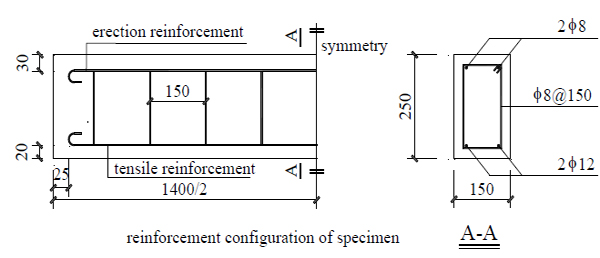
The program consisted of twenty 150mm×250mm×1400mm reinforced concrete beams that were reinforced with HPB300 steel bars. The details of the beams are shown in Fig. (1). The mechanical properties of concrete and steel are shown in Tables 2 and 3, respectively. Considering the corrosion levels, strengthening methods, and layers of CFRP, the number of specimens under different strengthening schemes is shown in Table 4.
| Elasticity modulus (GPa) |
Cubic compressive strength (MPa) |
Tensile strength (MPa) |
Poisson ratio |
|---|---|---|---|
| 30 | 33.3 | 3.15 | 0.193 |
| Yield strength fy (MPa) |
Ultimate strength fu (MPa) |
Elongation δ (%) | Elasticity modulus (MPa) |
|---|---|---|---|
| 307 | 452 | 31 | 2.26×10⁵ |
2.2. Accelerated Corrosion Process
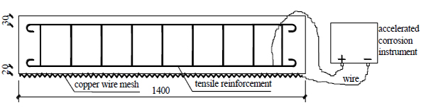
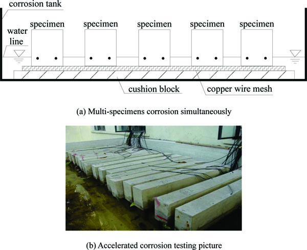
As shown in Fig. (2), an accelerated corrosion instrument was adopted to simulate corrosion by electrochemical methods, supplemented by wet-dry cycles environment. The accelerated corrosion instrument can provide DC power for 18 specimens at the same time and each specimen would not affect each other. In addition, the current intensity is constant during the process of corrosion and can be adjusted continuously within a certain scope. The accelerated corrosion test devices are shown in Figs. (2 and 3).
During the accelerated corrosion process, the salt content of water in the tank was kept at around 3% and the wet-dry cycle took 3 days, which consisted of wetting the beams for 1 day followed by 2 days of drying. The electric current flowed through the tensile reinforcement was about 800 mA, which corresponds to an approximate current density of 7.5μA/mm2. The time of corrosion depended on the designed corrosion level of each specimen.
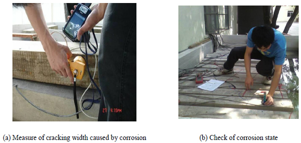
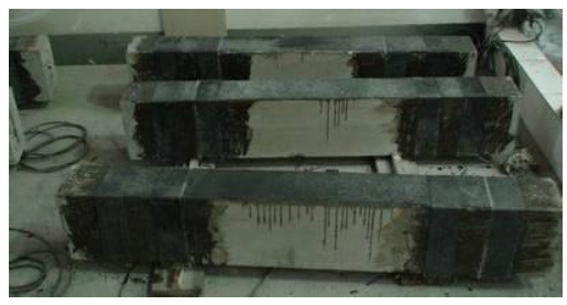
Although theoretical formulae have been proposed to judge the corroded status of the specimens, the test results still have variation due to the difference of material, current density, and the time of test. After the corrosion process, the cracks were the most visible phenomenon, therefore, at the end of the corrosion, the crack width was observed (shown in Fig. 4) and was selected as the main criteria to define the corrosion level of the specimens. In addition, the measured value of half-cell potential and the sectional loss rate of rebars were also adopted to detect the corrosion level of rebar for reference.
To measure the section loss rate, the corroded rebars were taken out from the broken beams after the static load test, and cleaned by dilute hydrochloric acid. Then the Vernier caliper was used to measure the cross sections with greater area loss, except those with obvious plastic necking deformation. Then the section shapes were drawn by AUTOCAD and their area could be calculated from it.
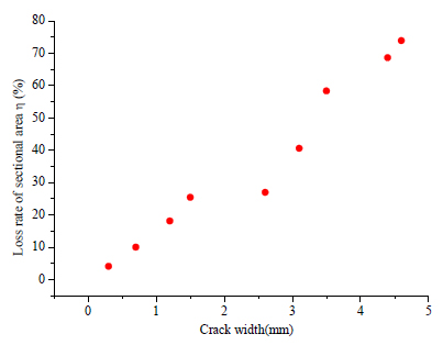
Fig. (5) demonstrates the maximum crack width and the corresponding loss rate of the sectional area η in the specimens with different corrosion level, which shows a relatively obvious linear relationship. Therefore, it is possible to judge the corrosion levels by crack width.
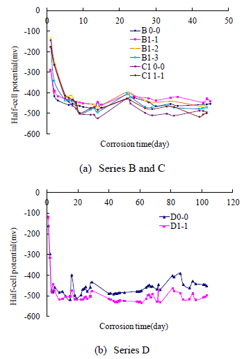
Fig. (6) shows the relationship between the corrosion time and the half-cell potential. According to ASTMC 876-80, measured potentials more positive than -200 mV, represent greater than 90% probability of no active corrosion; potentials between -200 and -350 mV, active corrosion is uncertain; and potentials more negative than -350 mV, there is greater than 90% probability of active corrosion. Fig. (6) indicates that the potentials in each beam quickly increased to a value negative than -350 mV in the first few days.
According to Table 1, two of the twenty specimens without cracks were classified as Level A, and the remaining eighteen corroded beams were classified into the other levels, four of which were Level B, five were C1, six were Level C2, and three were Level D. The details are shown in Table 4.
| Corrosion level |
Maximum crack width |
Unstrengthened beams |
Strengthened beams by DM | Strengthened beams by RM1 and RM2 | |||
|---|---|---|---|---|---|---|---|
| 1 layer | 2 layers | 3 layers | 1 layer | 2 layers | |||
| A | No cracks | 1 | 1 | - | - | - | - |
| B | 0.3mm | 1 | 1 | 1 | 1 | - | - |
| C1 | 1mm | 1 | 1 | 1 | 1 | 1 (RM1) | - |
| C2 | 3mm | 1 | 1 | 1 | 1 | 1 (RM1) | 1 (RM1) |
| D | >3mm | 1 | 1 | - | - | 1 (RM2) | - |
2.3. CFRP Repairing
Generally, the surfaces of corroded beams were chiseled and cleaned before bonding CFRP. However, for the on-sites corroded RC beams, it is a hard work to remove and rebuild the concrete cover before bonding the CFRP sheets. For beams with lower corrosion levels and small crack width, it is necessary to investigate that whether the CFRP sheets could be bonded directly to the surface of the concrete beam or not. Two strengthening methods were studied in this paper.
The composite Cymax L200-C, manufactured in Taiwan was used as the CFRP materials in this test, and its mechanical properties are listed in Table 5. The wet surface bonding binder with the adhesion strength no less than 2.5 MPa was adopted as the epoxy resin adhesive.
| Thickness (mm) |
Density (g/m2) |
Modulus of Elasticity E (GPa) |
Elongation when break |
Ultimate strength fu/MPa |
Ultimate strain (10-6) |
|---|---|---|---|---|---|
| 0.111 | 200 | 235 | 0.0168 | 3250 | 16800 |
2.3.1. Strengthening Method by Bonding CFRP Directly (DM)
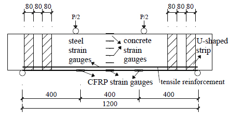
CFRP sheets were bonded directly on the bottom of the test beams, where usually the flexural and tensile region. The CFRP sheet was 1180mm long along the beam and the same width as the beam. In order to prevent the debonding failure, except Level B, two 80mm wide U-shaped strips spaced every 80mm were patched at each end of longitudinal CFRP. Fig. (7) shows the details of DM.
2.3.2. Strengthening Method by Bonding CFRP After Cutting or Chiseling Off Concrete (RM1 or RM2)
Strengthening method of bonding CFRP after cutting off concrete was suitable for the beams of level C1, C2, D with large crack width.
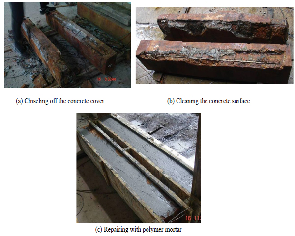
Before patching the CFRP, lossened concrete or the protection cover around the corroded rebars should be cut or chiseled away firstly, so that the rust of corroded rebar could be cleaned. Secondly, the protection cover was repaired according to the original size of the specimen with the epoxy polymer mortar. Finally, the specimen is strengthened by bonding CFRP sheets.
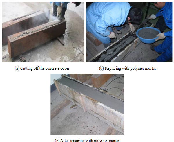
In this paper, two chiseling schemes were adopted in the process of dealing with the concrete. The first scheme (RM1) is suitable for the specimens with lower corrosion level. In this scheme, a V-shape groove was cut along the longitudinal cracks on the bottom of the beams, and then the CFRP sheets were bonded after repairing the grooves with polymer mortar. The process of RM1 is shown in Fig. (8). The second scheme (RM2) is suitable for the seriously corroded specimens in which the protection cover had become loosen, and there was severe slip between steel bars and concrete. Therefore, the loosened protection cover should be removed, then a form was established and new protection cover was built by the polymer mortar. Finally, the CFRP sheets were bonded. The process of RM2 is shown in Fig. (9).
Table 4 shows that among the twenty specimens, five were unstrengthened, eleven were repaired by DM, three were repaired by RM1, and one was strengthened by RM2.
2.4. Static Load Test
According to the corroded levels and the CFRP strengthening method, the specimens were named as Sm-n. S denotes the corrosion level; m is the different strengthening methods corresponding to 0~3, while 0 represents unstrengthening, 1 represents DM, 2 represents RM1, and 3 represents RM2; n is the number of CFRP sheets layers corresponding to 0~3, 0 represents unstrengthening. For example, C12-1 means the specimen is C1 corrosion level, the strengthening method is RM1 and the CFRP layer is 1. The number of specimens is shown in Table 6.
| Corrosion levels |
Name | Strengthened status | Ultimate load (kN) | Failure mode |
|---|---|---|---|---|
| A | A0-0 | unstrengthened | 102.74 | Under-reinforced beams fail |
| A1-1 | DM 1 layer | 150.58 | Over-reinforced beam failure | |
| B | B0-0 | unstrengthened | 99.39 | Under-reinforced beam failure |
| B1-1 | DM 1 layer | 140.54 | CFRP debonding | |
| B1-2 | DM 2 layers | 150.58 | CFRP debonding | |
| B1-3 | DM 3 layers | 160.62 | CFRP debonding | |
| C1 | C10-0 | unstrengthened | 93.71 | Under-reinforced beam failure |
| C11-1 | DM 1 layer | 135.53 | CFRP breaking | |
| C11-2 | DM 2 layers | 145.56 | U-wrap breaking,and debonding | |
| C11-3 | DM 3 layers | 152.25 | U-wrap breaking,and debonding | |
| C12-1 | RM1 1 layer | 132.18 | CFRP breaking | |
| C2 | C20-0 | unstrengthened | 82.00 | Under-reinforced beam failure |
| C21-1 | DM 1 layer | 118.80 | CFRP debonding | |
| C21-2 | DM 2 layers | 135.53 | CFRP debonding | |
| C21-3 | DM 3 layers | 148.91 | U-wrap breaking,and debonding | |
| C22-1 | RM1 1 layer | 138.87 | CFRP breaking | |
| C22-2 | RM1 2 layers | 172.33 | U-wrap breaking,and debonding | |
| D | D0-0 | unstrengthened | 58.58 | Scarce-reinforced beam failure |
| D1-1 | DM 1 layer | 55.23 | Shear failure | |
| D3-1 | RM2 1 layer | 76.98 | Shear failure |
A series of static load tests had been carried out on these corroded specimens to investigate the flexural behavior. The test device and the loading position are shown in Figs. (10 and 11).
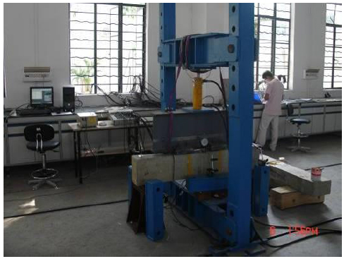
The strain of rebar, concrete, CFRP and the mid-span deflection of the beams were recorded, and the development of cracks and the failure modes of specimens were observed. The loading position and the layout of strain gauges are shown in Fig. (11). The concrete strain gauges were placed on both sides of the beams. The deflection of the beam was collected by linear variable differential transducer (LVDT). Both load and displacement control regimes were adopted during the tests.
3. EXPERIMENTAL RESULTS AND DISCUSSIONS
3.1. The Experiment Phenomena and Failure Mode
The experimental results of specimens are shown in Table 6. Part of the experimental failure modes of the specimens are shown in Fig. (12).
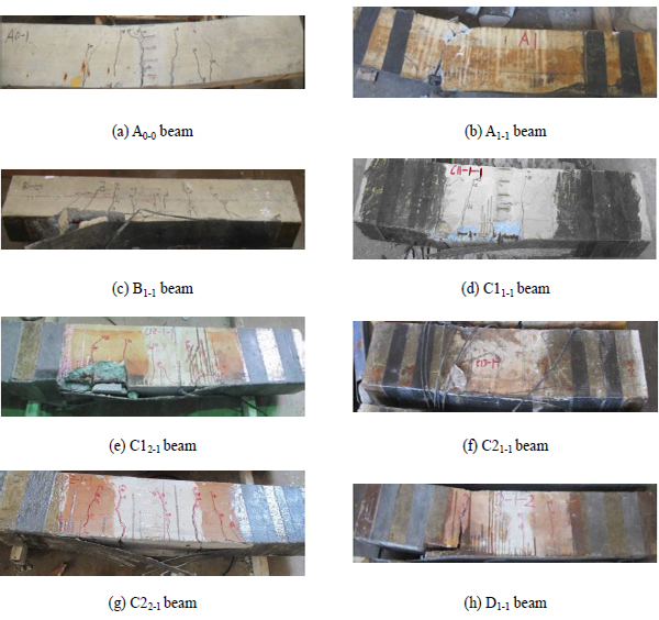
Typical flexural failure occurred in the unstrengthened specimens, A0-0, B0-0, C10-0, C20-0 and D0-0, and the cracks mainly appeared at the mid-span, most of which were vertical flexural cracks. The loading process was similar to the common RC members, and can be divided into three stages. No cracks appeared in the first stage, and in the second stage the cracks appeared and developed stably, and in the third stage the steel bars yielded and finally the concrete crashed. It can be seen from Table 6 that from corrosion Level A to D, as the steel area was gradually decreased due to corrosion, the flexural bearing capacity of the unstrengthened beams gradually decreased and the failure mode changed from the under-reinforced failure to scarce-reinforced failure.
For those specimens strengthened by CFRP, the test results is somewhat different to those unstrengthened ones. Part of the phenomenon of the experiment is summarized as followed,
- For specimen A1-1, whose corrosion level is A and one layer of CFRP was bonded, the cracks occurred later than A0-0 but developed rapidly. The concrete was finally crushed at the loading point and then the beam broke downward from the crush point suddenly followed by the fracture of CFRP U-shaped strips. It had the similarly failure as the over-reinforced beam.
- For specimens with Level B or C1 corrosion level and strengthened by DM, or with Level C1 or C2 corrosion level strengthened by RM1 or RM2, the failure modes were similar to under-reinforced failure of normal RC member. Next, the tensile concrete cracked and the strains of steel bars and carbon fiber increased rapidly, in which the steel bars played a more important role than the CFRP. Nevertheless, after the yielding of the steel bars, the strain of the CFRP keep on increasing. Finally, the CFRP fractured or deboned. For example, the CFRP and the concrete cover in B1-1 specimen debonded from the beam when the strain of CFRP increased to 7400με. The test results implies that the bearing capacity of the CFRP strengthening corroded RC beams was effectively enhannced, the crack width was restrained, and the flexural stiffness was improved.
- For the specimens with Level C2 corrosion and strengthened by DM or with Level D corrosion and strengthened by DM or RM2, the steel bars broke without obvious yielding for the sake of severely corrosion, and the specimens failed before the CFRP exerted its full strength. The cracks developed downward from the loading point and the U-wraps broke followed by the CFRP debonded. For these specimens with high corrosion level, the CFRP sheet couldn’t effectively prevent the cracks from developing. It may be because that there was a severe slip between the tensile steel bars and the concrete around results in lower bonding stress.
The test results indicates that the failure mode of the unstrengthened specimen with lower corrosion level A was under-reinforced failure, yet it might be over-reinforced failure when strengthened by CFRP. Therefore, if Level A members need to be strengthened, we should make sure that it would not be over-reinforced. As for level B or Level C1 specimens, although the steel bars lost some sectional area in corrosion, directly bonding CFRP sheet (DM) can still effectively prevent the cracks from developing and the failure mode of the beam can still be the under-reinforced failure. For Level C2 specimens, RM1 or RM2 is better than DM to strengthen the specimens. However, for Level D specimens, due to the excessive loss of steel bars area, the strengthening cannot effectively restrain the development of original cracks, and the scared-reinforced failure is likely to occur.
In summary, it is suggested that Level A, B and C1 corroded members can be strengthened by directly bonding CFRP. While the other level members should be strengthened by bonding CFRP after cutting and chiseling the concrete cover. In any case, the over-reinforced failure should be avoided.
3.2. Parametric Analysis
Following is the analysis on the ultimate flexural capacity of RC members strengthened by CFRP according to the experimental results. The influence of different strengthening methods and the CFRP layers is to be discussed.
(1) Influence of number of CFRP sheets layers on the ultimate flexural bearing capacity
Fig. (13) illustrates the comparison of bearing capacity between unstrengthened beams and beams strengthened by DM with different corrosion levels. In Fig. (13), 0-0 represents the unstrengthened beams, while 1-1, 1-2 and 1-3 represents the specimens strengthened by DM with 1 to 3 CFRP layers, respectively. Fig. (13) indicates that except level D, all the CFRP strengthening specimens have higher bearing capacity than the unstrengthened ones, and with the increase of the CFRP layers, the bearing capacity increases. Furthermore, generally with the increase of the corrosion levels, the bearing capacity of the specimens with the same CFRP layers decreases.
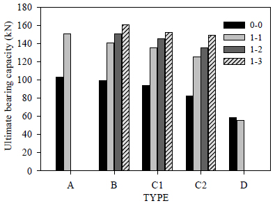
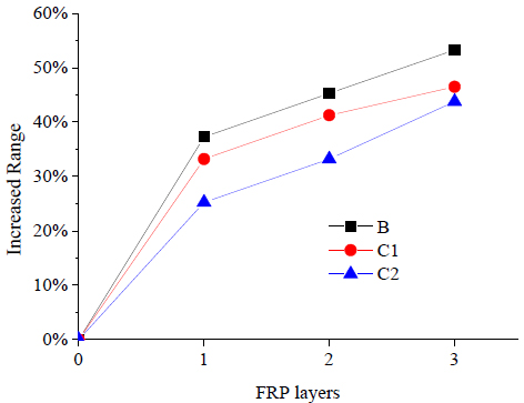
Fig. (14) shows the increased range of bearing capacity with different CFRP layers. It demonstrates that the bearing capacity increased significantly when strengthened by one layer of CFRP, The ultimate flexural capacity of members with one layer of CFRP raised by 30% to 50% than those unstrengthened ones. However, the trend slows down with the increase in the number of layers. Fig. (14) also shows that the increased range of bearing capacity declined with the growth of corrosion levels. This can be ascribed to the worse reinforcing situation under serious corrosion.
(2) Influence of different strengthening methods on bearing capacity
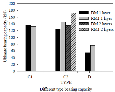
Fig. (15) presents the comparison of the increase of bearing capacity between the members with different corrosion levels under DM and RM1. As can be seen from the figure, for specimens with obvious cracks, it’s better to use RM to increase the bearing capacity than DM.
(3) Influence of different corrosion levels on stiffness
Figs. (16 and 17) show the load-middle span deflection curves of some specimens. As can be seen from Fig. (16), the final mid-span deflection of the unstrengthened beam A0-0 is 22mm, and the deflection of the strengthened beams is from 8mm to 15mm. Generally, the slope of the deflection curves of strengthened beams is greater than that of unstrengthened ones. The bearing capacity of the strengthened ones is higher than that of unstrengthened ones, yet the ductility of the strengthened ones are lower than that of the unstrengthened ones. This indicates that strengthened by CFRP is capable of improving the deformation performance and the integral stiffness of the beams obviously yet decreasing the ductility.
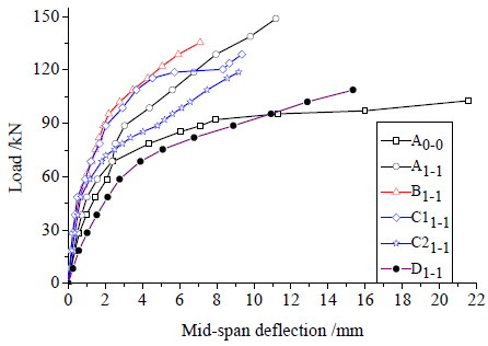
Except A1-1, under the same loading, larger deflection of the specimen can be achieved with the increase of the corrosion level. That means the mid-span deflection of the specimens was greater and their integral stiffness was weaker with the growth of the corrosion levels. It can be concluded that the cracking caused by corrosion has a great impact on the integral stiffness of strengthened beams. The more severe the corrosion, the greater impact on stiffness is and the worse reinforcing effect is.
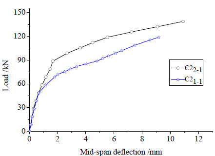
Fig. (17) demonstrates the load-deflection curves of C2 under two different strengthening methods (DM and RM1), it can be seen that the initial stiffness is close yet the bearing capacity is different, therefore for the specimens with serious cracks conditions, RM1 or RM2 is recommended for repair.
4. CALCULATION OF FLEXURAL BEARING CAPACITY OF CFRP STRENGTHENING CORRODED RC BEAMS
Currently some formulas for the calculation of flexural bearing capacity of corroded concrete beam or CFRP strengthening beams have been proposed separately. However, few researches have been focused on the bearing capacity calculation of CFRP strengthening corroded RC beams. In the following, the flexural bearing capacity of the CFRP strengthening corroded RC beam is to be studied.
(1) Calculation of flexural bearing capacity of corroded RC beams
There are some relevant provisions of bearing capacity calculation methods for corroded RC concrete members in Chinese related codes. According to Technical Specification for Detection and Assessment of Harbour and Marine Structures (JTJ302-2006) [17] , Design Code for Concrete structures of Port and Waterway Engineering (JTS151-2011) [18], the calculation formulas for the flexural bearing capacity of corroded RC members are shown as follows:
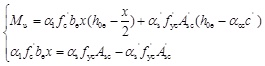
Where, fc' is the concrete strength on site, be is the equivalent cross-sectional width,
 , αcc is the protective layer damage coefficient, ci is the cover thickness on one side, h0e is the effective height of equivalent section,
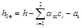 ; αs is the utilization coefficient of steel strength, which is determined by crack status of concrete cover and depth of steel corrosion, fyc and f ′yc are the designed value of steel bar strength after corrosion, fyc can be defined as:
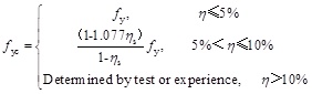
Where, η is the loss rate of the sectional area of the steel bar, fy is the strength of the original steel bars.
(2) Calculation of flexural bearing capacity of CFRP strengthening RC beams
For the rectangular flexural RC member strengthened by CFRP, Code for design of strengthening concrete structure (GB 50367-2013) [19] provides calculation formulas as follows:
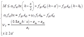
where, b and h are the width and height of the section ;fy0 and f′y0are tensile strength and compressive strength of tensile and compressive bars; As0and A′s0 are sectional area of tensile bars and compressive bars; a′ is the distance from the resultant force action points of compressive bars to the compressive edge of section; ftis tensile strength of CFRP; Afc is the effective sectional area of CFRP; ψf(≤1) is strength utilization coefficient, considering that CFRP’s practical tensile strain cannot reach its design value; εcu=0.0033 is the maximum pressure strain of concrete; εf is the strain designed value of CFRP; εf0 is the delayed strain of CFRP when considering the secondary load in strengthening.
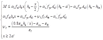
In this paper, formula (1) and formula (3) are combined into formula (4) for calculating the flexural bearing capacity CFRP strengthening corroded RC beams. It can be seen that h0, be, fy 0, and f′ y0 take the place of h, b, αsfyc and αsf′ yc, respectively.
Besides Chinese Code, the calculation formulas proposed by British Standard (BS8110-1997) [20], and fibBulletin 14 Externally Bonded FRP Reinforcement for RC Structures [21] for CFRP strengthening RC members were also adopted to combine with formula (1) for investigation.
Table 7 shows the comparison between experimental and calculated results of flexural capacity of the specimens, the maximum loss rate of the steel bar area are measured after the static test.
| Corrosion levels |
Name of specimens |
Percentage of loss of sectional area η |
ultimate load Nu(kN) |
NBri(kN) [NBri/ Nu] |
NFib(kN) [NFib/ Nu] |
NF4 (kN) [NF4/ Nu] |
NF5(kN) [NF5/ Nu] |
|---|---|---|---|---|---|---|---|
| A | A0-0 | 0 | 102.74 | - | - | 71.60[0.7] | 71.60[0.70] |
| A1-1 | 0 | 150.58 | 88.38[0.59] | 132.75[0.88] | 132.23[0.88] | 132.23[0.88] | |
| B | B0-0 | 5.00% | 99.39 | - | - | 68.06[0.68] | 68.06[0.68] |
| B1-1 | 5.00% | 140.54 | 88.49[0.63] | 129.45[0.92] | 128.95[0.92] | 128.95[0.92] | |
| B1-2 | 5.00% | 150.58 | 134.47[0.89] | 170.85[1.13] | 188.30[1.25] | 153.15[1.02] | |
| B1-3 | 5.00% | 160.62 | 154.91[0.96] | 191.70[1.19] | 238.57[1.49] | 167.97[1.05] | |
| C1 | C10-0 | 14.05% | 93.71 | - | - | 59.55[0.64] | 59.55[0.64] |
| C11-1 | 7.84% | 135.53 | 88.55[0.65] | 127.40[0.94] | 127.09[0.94] | 127.09[0.94] | |
| C11-2 | 3.44% | 145.56 | 134.39[0.92] | 172.10[1.18] | 189.28[1.30] | 154.16[1.06] | |
| C11-3 | 9.50% | 152.25 | 155.81[1.02] | 190.45[1.25] | 236.73[1.55] | 165.09[1.08] | |
| C12-1 | 15.00% | 132.18 | 88.49[0.67] | 122.55[0.93] | 122.38[0.93] | 122.38[0.93] | |
| C2 | C20-0 | 24.24% | 82 | - | - | 52.56[0.64] | 52.56[0.64] |
| C21-1 | 39.07% | 118.80 | 89.10[0.75] | 106.40[0.90] | 106.49[0.90] | 106.49[0.90] | |
| C21-2 | 52.59% | 135.53 | 136.73[1.01] | 149.65[1.10] | 158.14[1.17] | 122.23[0.90] | |
| C21-3 | 50.00% | 148.91 | 163.87[1.10] | 170.75[1.15] | 216.49[1.45] | 139.04[0.93] | |
| C22-1 | 53.95% | 138.87 | 89.28[0.64] | 96.20[0.69] | 96.61[0.70] | 96.61[0.70] | |
| C22-2 | 44.39% | 172.33 | 136.38[0.79] | 157.55[0.91] | 163.37[0.95] | 127.59[0.74] | |
| D | D0-0 | 52.00% | 58.58 | - | - | 33.43[0.57] | 33.43[0.57] |
| D1-1 | 68.17% | 55.23 | 89.40[1.62] | 86.55[1.57] | 87.13[1.58] | 87.13[1.58] | |
| D3-1 | 69.84% | 76.98 | 89.41[1.16] | 85.35[1.11] | 86.01[1.12] | 86.01[1.12] |
Notes: NBri, NFib, NF4, NF5= the corresponding calculated bearing capacity load from British standard, Fib bulletin, Formula (4), Formula (5) respectively.
It can be seen that, in the case of 1 layer of CFRP sheet, formula (4) based on Chinese Code and fib Bulletin [21] can give well prediction, yet in the case of 2 or 3 layers of CFRP sheet, British Code [20] gives more close results. Both the experimental and calculated results increase with the growth of CFRP layers, however the increase rate of experimental results is slower than that of calculated results. In addition, shear failure occurs in the beams under the corrosion level D, which would lead to lower experimental results than the calculated results by all the codes.
It’s worth noting that for the multi-layer CFRP strengthening RC members, the adhesives are used to bond together multiple layers of CFRP laminates, and the practical effect of using multi-layer CFRP is lower than that of the one-layer CFRP with same area [19].
Therefore, a fiber area reduction coefficient km was introduced in this paper, while km =1.0 for 1-layer CFRP, km =0.7 for 2-layer CFRP and km =0.55 for 3-layer CFRP is proposed. Then formula (4) is revised to formula (5).
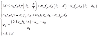
The calculated results are listed in Table 7, which indicates that, for the multi-layer CFRP strengthening beams, the formula (5) provides a better prediction on the ultimate flexural strength of the member than formula (4).
Due to limited number of the specimens, further researches should be carried out for a more accurate calculation formula for flexural bearing capacity CFRP strengthening corroded RC beams.
CONCLUSION
In this paper, in order to investigate the flexural behavior of CFRP strengthening corroded RC beam under different corrosion levels, a series of tests on twenty RC beams were carried out. Based on the experimental and analytical results, the following conclusions can be drawn:
- Based on crack width and loss rate of the sectional area, a classification table for evaluating the corrosion levels of the corroded reinforced concrete (RC) beams is presented. The results indicate that the corrosion levels of the members can be effectively classified.
- The bearing capacity of the CFRP strengthening corroded RC beams were significantly improved, the cracks width was restrained, and the flexural stiffness was increased. The ultimate flexural capacity of members with one layer of CFRP raised by 30% to 50% than those unstrengthened ones. However, with the increase of the corrosion level, the enhancement of CFRP decreased. With the increase of the CFRP layers, the bearing capacity increase, however, the increasing ratio reduced with the increase of layers.
- For specimens with obvious cracks, the effectiveness of the strengthening method by bonding CFRP after cutting or chiseling off concrete method (RM1 or RM2) is higher than the method of bonding CFRP directly (DM). It is suggested that the corroded RC members with Level A, B or C1 can be strengthened by DM, while the other level members should be strengthened by RM1 or RM2. In any case, the over-reinforced failure should be avoided.
- The formulae in current design code were used to calculate the flexural bearing capacity of the RC beam strengthened with CFRP, and a revised formula that can give a better prediction for multi-layers CFRP strengthening corroded RC members is proposed.
CONFLICT OF INTEREST
The authors confirm that this article content has no conflict of interest.
ACKNOWLEDGEMENTS
Funding for this research project was provided by Research and Development Project of Traffic Construction Technology of China (2007-ZJKJ-04), the State Key Lab of Subtropical Building Science, South China University of Technology (2013ZC19). The support for the research is acknowledged with thanks.

