All published articles of this journal are available on ScienceDirect.

Anisotropic Nonlinear Elastic Model of Concrete and Secondary Development in ABAQUS
Abstract
In order to solve the convergence problem of concrete constitutive in the softening phase, an anisotropic nonlinear elastic constitutive model (ANECM) was proposed, which was developed based on the uniaxial concrete constitutive relation in the Chinese code for design of concrete structures (GB 50010-2010). The user material subroutine (UMAT) based on ANECM is developed in ABAQUS software. The above UMAT is applied to analyze a simulation model in ABAQUS software. The result shows that compared to the default plastic-damage concrete constitutive in ABAQUS, ANECM is an effective and appropriate model to simulate the performance of concrete and it has improved the convergence problem.
1. INTRODUCTION
Concrete is a widely used material in civil engineering applications. The correct understanding of concrete behavior is an essential part for design [1]. Many scholars have done a lot of experiments and theoretical studies and proposed a variety of concrete constitutive models. These models can be divided into 4 parts: 1. The linear elastic model, 2. The nonlinear elastic model [2], 3. The plasticity theoretical model [3-7], 4. The other mechanics theoretical model [8]. Among these models, the plasticity theoretical model has been used extensively in recent years to describe the behavior of concrete. However, still some disadvantages limit the development of this model, such as the parameters of plasticity model are difficult to determine, and the convergence problem of concrete constitutive in the softening phase.
With the improvement of the material constitutive theory, more and more scholars considered the concrete material as anisotropic material. The anisotropic damage model can properly interpret the damage development in concrete material by describing the underlying micromechanical processes of micro-defects [9, 10]. In this paper, an anisotropic nonlinear elastic constitutive model (ANECM) was proposed. ANECM is the simplified method based on the uniaxial concrete constitutive relation in the Chinese code for design of concrete structures (GB 50010-2010), and this model expands uniaxial concrete stress-strain behavior into three principle directions and simulates the anisotropic nonlinear behavior of concrete by using the secant moduli to calculate the updated stresses. The secant modulus in uniaxial concrete constitutive relation is always positive, which can prevent the convergence problem in the iterative process of concrete constitutive. Compared to the default plastic-damage concrete constitutive in ABAQUS, ANECM is an effective and appropriate model to simulate the performance of concrete.
2. THE FORMULAS OF CONCRETE CONSTITUTIVE RELATION
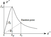
The stress-strain behavior of the concrete material can be separated into tension and compression components. The distinctive behavior of concrete has increased the complexity of the constitutive model. The tension part of the concrete stress-strain curve in the code for design of concrete structures (GB 50010-2010) is described as Formula 1:
 |
(1) |
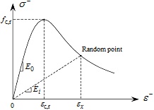
And the compression part of the concrete stress-strain curve is described as Formula 2.
 |
(2) |
where dt is a tensile damage parameter, dc is a compressive damage parameter, Ec is the initial elastic modulus of concrete. In the code for design of concrete structures (GB 50010-2010), the formulas of dt and dc are as follows:
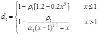 |
(3) |
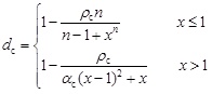 |
(4) |
where
 ,
,
 ,
,
 . In Formula 3,
 is the concrete peak tensile strain, ft,r is the corresponding value of concrete tensile strength at εt,r and αt is a descending parameter of tension part. In Formula 4,
 is the concrete peak compressive strain, fc,r is the corresponding value of concrete compressive strength at εc,r and αc is a descending parameter of compression part. The corresponding values of αt and αc may refer to Table 1.
| ft,r(N/mm2) | 1.0 | 1.5 | 2.0 | 2.5 | 3.0 | 3.5 | 4.0 |
| αt | 0.31 | 0.70 | 1.25 | 1.95 | 2.81 | 3.82 | 5.00 |
| fc,r(N/mm2) | 20 | 25 | 30 | 35 | 40 | 45 | 50 |
| αc | 0.74 | 1.06 | 1.36 | 1.65 | 1.94 | 2.21 | 2.48 |
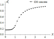
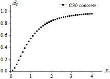
Taking C30 concrete as an example, the evolutions of dt and dc with respect to variable x are shown in Figs. (1 and 2), respectively. And the diagrammatic sketches of the concrete uniaxial behavior under tension condition and compression condition are shown in Figs. (3 and 4), respectively.
3. ANECM
ANECM is proposed to simulate the concrete behavior subjected to the complex stress-strain condition. The concrete constitutive relation in ANECM is based on Formula1 and Formula 2, which respectively describe the tension part and the compression part of the concrete uniaxial behavior. How to apply the uniaxial concrete behavior into Three-dimensional space is the key point. In three-dimensional stress-strain conditions, one of the main difficulties in simulating the concrete behavior is the proper stiffness matrix in the iterative calculations. In this chapter, the stiffness matrix used in ANECM will be described in detail.
The stiffness matrix of concrete is denoted as [D]. In three-dimensional stress-strain conditions, the stress-strain relation is described as Formula 5:
 |
(5) |
where
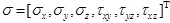 ,
,
 .
.
From Formula 5, the stresses value can be calculated by the corresponding strains value.
In order to expand the uniaxial concrete stress-strain relation into the three-dimensional concrete stress-strain relation, there are 4 steps to achieve this purpose.
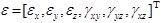
3.1. Calculate Principal Strains from General Strains
In the complex stress-strain state, the concrete behavior follows the uniaxial stress-strain relation in each principal direction. In general speaking, the stresses values (or the strains values) in principal directions are not the same as those in general directions. The strains states in general directions and in principal directions are shown in Fig. (5).
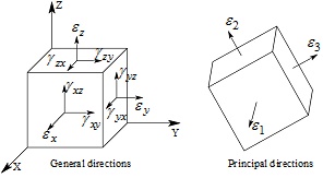
The transformation from the general strains state
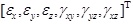 to the principal strains state
 can be accomplished by the principal strain conversion matrix [T1]. The formula is expressed as follows.
 |
(6) |
It is important to notice that εxy=γxy/2, εyz=γyz/2 , εxz=γxz/2.
The principal strain conversion matrix [T1] is expressed in Formula 7 [11]:
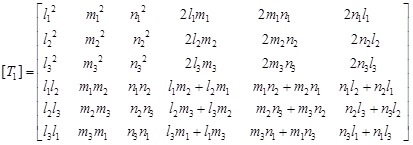 |
(7) |
where l2+m2+n2=1, and the values of l, m and n can be calculated by Formula 8.
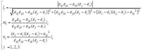 |
(8) |
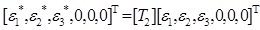
3.2. Calculate Effective Principal Strains from Principal Strains
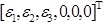
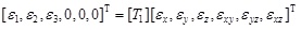
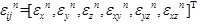
In ANECM, the effective principal strains [ε1*, ε2*, ε3*, 0, 0, 0]T are exactly following the uniaxial stress-strain rules, which can be calculated from the principal strains [ε1, ε2, ε3, 0, 0, 0]T by Formula 9.
 |
(9) |
where [T2] is the effective principal strain conversion matrix, and it is described as follow:
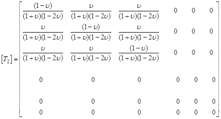 |
(10) |
where υ is Poisson’s ratio of the concrete material.
3.3. Calculate Principal Stresses from Effective Principal Strains
In each principal direction, the relation between principal stresses and effective principal strains follows the change law of uniaxial concrete constitutive relation, and the calculation of the secant modulus in each principle direction is independent of each other. The relation between principal stresses and effective principal strains is described as Formula 11:
 |
(11) |
where [D1] is the secant matrix, and it is described as Formula 12:
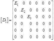 |
(12) |
where Ei is the secant modulus which is corresponding to the effective principal strains state. The formula of Ei is as follows: In the tension condition, Ei=(1-dti)Ec. In the compression condition, Ei=(1-dci)Ec.
3.4. Calculate General Stresses from Principal Stresses
The general stresses is corresponding to the global coordinate system. In the iterative process, it is convenient to update the stresses in the global coordinate system. The general stresses can be calculated from the principal stresses by Formula 13:
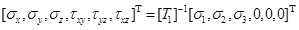 |
(13) |
where [T1] is the principal strain conversion matrix.
It can be concluded from the Formulas of 5, 6, 9, 11 and 13 that the expression of the concrete stiffness matrix can be written in the following form.
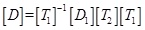 |
(14) |
Therefore, the general stresses can be calculated from the general strains by Formula 15.
 |
(15) |
Analogous to Formula 5, Formula 15 is the stress-strain relationship used in ANECM.
4. THE SECONDARY DEVELOPMENT IN ABAQUS
How to apply ANECM in ABAQUS software? First, it is needed to know the iteration principal in ABAQUS [12-15]. The main purposes of the constitutive iteration in ABAQUS are the stiffness matrix calculation and the stresses update. The stiffness matrix [D] can be calculated from Formula 14 and the stresses σijn+1 are updated based on the parameters of σijn, εijn and dεijn. The updated stresses σijn+1 are calculated by Formula 16:
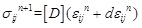 |
(16) |
where,
 ,
,
 ,
,
 .
.
It should be noticed that, each of the secant modulus E1, E2 and E3 in the stiffness matrix [D] has two forms which respectively corresponding to the tension state and the compression state. The effective principal strains [ε1*, ε2*, ε3*, 0, 0, 0]T are the key factors to judge the states. As the effective principal strain εi* is positive, in the corresponding principal direction, Concrete material is considered to be in a state of tension and dti should be selected as a damage parameter in the calculation process of Ei. In contrast, as the effective principal strain εi* is negative, in the corresponding principal direction, Concrete material is considered to be in a state of compression and dci should be selected as a damage parameter in the calculation process of Ei.
From Formula 16 it can be known that the updated stresses are calculated directly from the updated strains and it is not affected by the last step stresses. The iteration process in Formula 16 is called full incremental iterative method. In this method, the secant moduli in the stiffness matrix [D] are always kept positive. That means there is no singular problem in the stiffness matrix during the constitutive iteration [16]. In other words, in the process of solving displacement, it can directly calculate the inverse stiffness matrix [D]-1, and there is no convergence problem during the constitutive iteration.
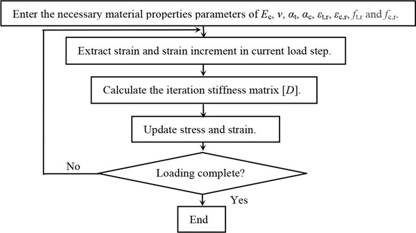
The algorithm flow chart of the constitutive iteration in ABAQUS is as Fig (6):
5. THE SIMULATION EXAMPLE
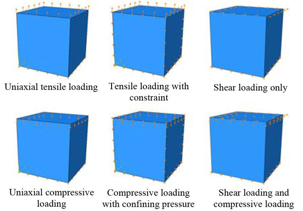
In order to text the proposed ANECM, a simulation example is taken in ABAQUS software, which is shown in Fig. (7). Because the main purpose of the simulation is to verify the correctness of the algorithm in ANECM, the finite element model size is chosen as 1m×1m×1m and the mesh size is chosen as 1m. Meanwhile the parameters of the concrete material property applied in the example are shown in Table 2.
| Parameters | Ec | ν | αt | αc | ft,r | fc,r | εt,r | εc,r |
| Value | 30000MPa | 0.3 | 2.81 | 1.36 | 3MPa | 30MPa | 0.000118 | 0.00164 |
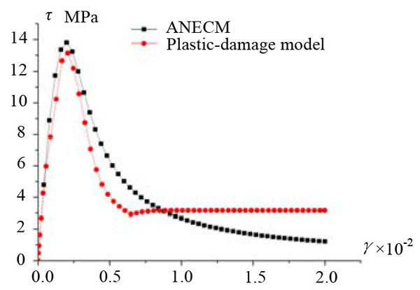
ANECM and the plastic-damage model are taken to analyze the simulation model, respectively. The calculated stress-stain curves in various loading conditions are shown in Figs. (8-13).
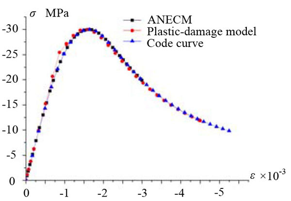
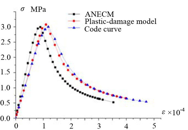
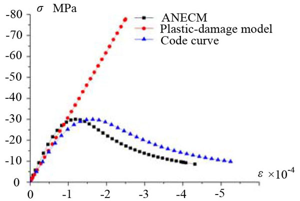
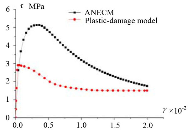
In Figs. (8-11), it can be seen that, under the uniaxial tensile loading (or the uniaxial compressive loading) without confining pressure, there is a generally good agreement in the shape of the curves calculated from ANECM and the plastic-damage model. But when the confining pressure is under consideration, the curves calculated from ANECM and the plastic-damage model have a bit difference. Compared to the plastic-damage model curve, the peak strain in ANECM curve is reduced due to the influence of the surrounding pressure, and because the plastic damage-model can not effectively simulate the mechanical behavior of concrete under high confining pressure (which is mentioned in Abaqus Analysis User’s Guide), the shape of the curve calculated by the plastic-damage model in Fig. (11) is obviously different from others. In Figs. (12 and 13), it is shown that the curves calculated by ANECM and the plastic-damage model have presented the same tendency while the simulation model is under shear loading and under complicated loading (shear loading and compressive loading).
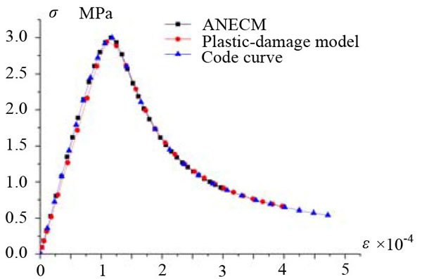
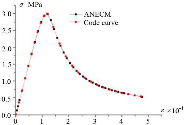
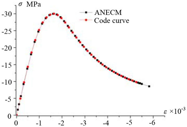
It should be noticed that, the stress-strain relation in principal directions are strictly following the code curve when ANECM is taken to analyze, which can be proved in Figs. (14 and 15). It means in three-dimensional space, ANECM successfully represented the code curves in principal directions. As we have seen, whether ANECM can effectively simulate the concrete performance is depended on the selected uniaxial constitutive model. Meanwhile, because the chosen constitutive model is not contained the stiffness recovery factors, ANECM is not suitable to simulate the performance of concrete under cyclic loading.
CONCLUSION
In this paper, ANECM was proposed to simulate the concrete behavior and a simulation model was taken to analyze. The result shows that compared to the default plastic-damage concrete constitutive in ABAQUS, ANECM is an effective and appropriate model to simulate the performance of concrete and it has improved the convergence problem.
However, ANECM still has the following limitations. 1) The calculation accuracy of ANECM is depended on the selected constitutive model. 2) ANECM is not suitable to simulate the performance of concrete under cyclic loading. For improving the above deficiencies, further work is being studied.
CONFLICT OF INTEREST
The authors confirm that this article content has no conflict of interest.
ACKNOWLEDGEMENTS
The project was supported by the National Nature Science Foundation of China (Grant No. 51008085).

