All published articles of this journal are available on ScienceDirect.

Inelastic Test and Design Method of Cold-formed Steel Lipped Channel Members in Bending
Abstract
The aim of this paper is to investigate the inelastic bending capacity and design method of cold-formed steel lipped channel bending members. The bending tests were conducted on 30 cold-formed steel lipped channel members. The nominal yield stress and the nominal thickness of the bending members were 235 MPa and 2mm. The theoretical global buckling stress was higher three times than the yield stress which can make sure the failure of members were in inelastic stage. For each specimen, an analytical analysis using Finite Element Method (FEM) was also conducted considering the influence of the boundary, the ultimate bending capacity, and the failure mode could also be captured. The test results show that the Chinese cold-formed steel specification Technical code of cold-formed thin-walled steel structures (GB50018-2002) is conservative for lipped channel bending sections in inelastic stage. The test results are used to put forward to a revised design method based on effective width method for the current Chinese cold-formed steel specification. The comparison on the bending capacity between the test results and the calculated results by using the proposed method, effective width method and direct strength method in North American cold-formed steel specification (AISI-S120-2016(draft)) shows that the proposed method can consider the inelastic reserve capacity of bending members well. The failure modes and bending capacity of bending members obtained using the idealized shell finite element model, which are close to the experimental results, shows that the idealized model is very well to model the buckling behavior and calculate capacity of bending members.
1. INTRODUCTION
Cold-formed steel members have been widely used in the secondary structural elements in portal frame building in China, in which the thickness of sections is between 1.5 and 6 mm. The cold-formed steel sections have been used in the domestic and agricultural structure as primary structures recently in China. Meanwhile, the application of residential buildings in China has an increased trend in recent years.
The ultimate moment capacity of cold-formed members can be calculated by using the effective width method (EWM) considering local buckling in North American [1] and Australian [2] cold-formed steel specification. The determining of distortional buckling using EWM in these two specifications is complicate. Direct strength method (DSM) has been found in the North American and Australia cold-formed specifications as an alternative design method to calculate the ultimate capacity of cold-formed steel members which is based on researches by Schafer and Pekoz [3] and Schafer [4]. Chinese cold-formed steel specification (Technical code of cold-formed thin-walled steel structures (GB50018-2002)) [5] uses the EWM to predict the ultimate capacity of the cold-formed steel lipped channel members, in which the local buckling interaction of elements is considered and distortional buckling is handled via a lower reduced plate buckling coefficient for the partially stiffened element.
EWM and DSM assume that the members attain in the ultimate condition when any fiber in sections reaches in the yield stress. While the members can exceed the initial yield stress and reach higher capacity which is called inelastic reserved capacity. Yener and Pekoz [6, 7] studied the inelastic reserve capacity for cold-formed steel beams and further put forward the design method of EWM for calculating the inelastic bending capacity according to the calculated maximum compressive strain in stiffened elements. The further method for unstiffened elements was developed by Bambach and Rasmussen [8]. These methods are used to calculate the strength of cold-formed steel sections without taking into account in the lateral-torsional buckling, local and distortional buckling. Shifferaw and Schafer [9] proposed an element-based EWM to predict the inelastic reserve capacity of bending members accounting for lateral-torsional buckling and local buckling and DSM considering global(lateral-torsional buckling), local and distortional buckling. These calculation method can be found in the draft of North American [10]. On the basis of experimental and analytical investigations performed by Maduliat, Bambach, and Zhao [11], a revision method for DSM to consider the inelastic reserve capacity was suggested. The test about interact buckling of bending members carried out in China by Zhang [12] displayed that cold-formed steel beams had a 15-25% inelastic reserve capacity higher than the yield strength.
However, little attention is conducted about the design method of inelastic reserve capacity of bending members based on EWM accounting for global, local and distortional buckling. The aim of this paper is to conduct experimental and analytical investigations of inelastic reserve capacity, and to put forward a general design approach to consider the inelastic reserve of the strength and stability capacity including global, local, and distortional buckling for cold-formed steel bending members based on effective width method.
2. EXPERIMENTAL SETUP AND SPECIMENS
2.1. Test Set-up
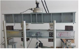
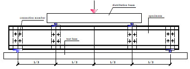
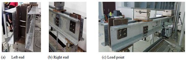
The overall view and the schematic view of our-point bending test arrangements are shown in Figs. (1 and 2). The beams were simply supported. The hinge support was simulated by roller support and slide support. The roller support was simulated by round bar which allows in-plane rotation and the slide support was simulated by slide block under the round bar which allows translation movement along the specimen. Two lipped channels were tested at the same time that bolted to T-shaped steel connective blocks. These steel connectors were located at the loading points and end supports. The sectional views at the loading points and end supports of the T-shaped steel blocks are detailed in Fig. (3). The four-point bending tests were loaded symmetrically at two points to the T-shaped steel blocks through a spread beam. A 100kN hydraulic jack testing machine was used to apply a downward force to the spread beam, as shown in Fig. (3). Round bar were also used at the two loading points. In this testing arrangement, pure in-plane bending of the specimens can be obtained between the two loading points without the presence of shear and axial forces, keep the two test members work together, and minimize the web crippling at the ends and load points. Near the 90% ultimate load, the static load was paused for half minute and loaded again. This allowed the stress relaxation with the occurrence of the plastics. A data acquisition system was used to record the displacement transducers and load readings during the tests. Displacement control was adopted to drive the hydraulic actuator a constant rate of 0.3 mm/min for the four-point bending tests. Three displacement transducers were positioned at the tension flange near the flange-web junctions of the two loading points and the mid-span point to measure the vertical deflection and curvature of the beams. One transducer was positioned near the compressive flange of web at mid-span to monitor the possible local buckling or distortional buckling.
2.2. Material Properties
Tension tests were conducted following the provisions of Metallic materials--Tensile testing--Part 1: Method of test at room temperature (GB/T228.1-2010) [13]. Six tensile coupons were cut from two ends of a test member including the web flat, the compression flange, and the tension flange. A 200kN capacity testing machine was used for applying load. The mean values of six coupon test results are summarized. The specimen yield stress, fy, is 295MPa, and the steel elastic modulus, E, is assumed as 2.074x10⁵Mpa, and the specimens elongation is 32%.
2.3. Section Dimensions
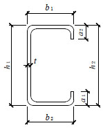
The dimensions and nomenclature for each specimen is presented in Fig. (4), and the measured value was recorded at 1/4 and 1/2 points in pure bending part, so there are three measurement locations for each specimen. The measured mean values for specimens are summarized in Table 1. The test specimens were labeled with characteristic information such that each beam can be easily identified. For example, the label “B600H160-1a”, where “B” means pure bending member, “600” indicates the pure bending length of specimen, “H160” refers that the nominal width of web is 160mm, If a test was repeated, then a symbol of “1” was added which means different repeated group. Finally, “a” indicates one lipped channel of a pair of channels tested at the same time. The inside bend radius of specimens is 2t, where t is the base thickness of members. The elastic theoretical local and distortional buckling moments (Mcrl and Mcrd) determined using CUFSM [14]. The yield moments (My), the plastic moments (Mp), and the nominal effective length (L) which is the distance between the loaded points for each specimen are reported in Table 1. The theoretical elastic buckling moments including local and/or distortional buckling of specimens are approximate to three times the yield moments which can ensure the occurrence of the elastic local or distortional buckling.
| Specimens |
L (mm) |
h1 (mm) |
h2 (mm) |
b1 (mm) |
b2 (mm) |
a1 (mm) |
a2 (mm) |
t (mm) |
My (kN.m) |
Mp (kN.m) |
Mcrl (kN.m) |
Mcrd (kN.m) |
|---|---|---|---|---|---|---|---|---|---|---|---|---|
| B600H160-1a | 600 | 156.0 | 157.0 | 58.24 | 57.99 | 17.00 | 16.29 | 1.95 | 8.00 | 8.98 | 21.56 | 14.78 |
| B600H160-1b | 600 | 158.0 | 156.0 | 58.32 | 58.24 | 17.75 | 19.18 | 1.98 | 8.26 | 9.29 | 22.83 | 16.53 |
| B600H160-2a | 600 | 156.0 | 157.0 | 58.19 | 58.72 | 17.99 | 17.82 | 1.93 | 8.01 | 9.00 | 21.04 | 16.56 |
| B600H160-2b | 600 | 157.0 | 159.0 | 58.60 | 58.46 | 17.60 | 17.95 | 1.95 | 8.19 | 9.21 | 21.66 | 15.55 |
| B600H160-3a | 600 | 159.0 | 158.0 | 58.22 | 59.67 | 18.06 | 18.34 | 1.95 | 8.28 | 9.31 | 21.76 | 15.86 |
| B600H160-3b | 600 | 157.0 | 158.0 | 58.27 | 58.19 | 17.92 | 18.54 | 1.93 | 8.07 | 9.08 | 21.07 | 15.60 |
| B600H180-1a | 600 | 172.0 | 178.0 | 60.59 | 60.30 | 12.50 | 13.25 | 1.95 | 9.23 | 10.40 | 20.35 | 12.68 |
| B600H180-1b | 600 | 177.0 | 181.0 | 58.25 | 58.42 | 15.54 | 9.19 | 1.94 | 9.23 | 10.45 | 20.03 | 18.77 |
| B900H140-1a | 900 | 137.0 | 137.0 | 38.32 | 38.98 | 15.72 | 16.88 | 1.95 | 5.33 | 6.12 | 20.50 | 16.71 |
| B900H140-1b | 900 | 137.0 | 135.0 | 38.96 | 38.99 | 15.66 | 16.37 | 1.95 | 5.17 | 6.06 | 20.14 | 16.11 |
| B900H140-2a | 900 | 138.0 | 136.0 | 38.38 | 39.10 | 15.56 | 18.03 | 1.96 | 5.19 | 6.18 | 20.34 | 16.82 |
| B900H140-2b | 900 | 138.0 | 135.0 | 38.12 | 38.16 | 16.28 | 15.64 | 1.92 | 5.05 | 5.94 | 19.09 | 15.67 |
| B900H140-3a | 900 | 138.0 | 136.0 | 38.11 | 38.14 | 15.74 | 17.05 | 1.93 | 5.12 | 6.03 | 19.44 | 16.05 |
| B900H140-3b | 900 | 137.0 | 138.0 | 38.36 | 38.10 | 15.81 | 15.71 | 1.96 | 5.19 | 6.12 | 20.13 | 16.26 |
| B900H180-1a | 900 | 173.0 | 178.0 | 61.15 | 61.73 | 13.77 | 14.37 | 1.95 | 9.50 | 10.63 | 20.77 | 13.53 |
| B900H180-1b | 900 | 174.0 | 179.0 | 60.51 | 60.95 | 13.80 | 13.34 | 1.96 | 9.52 | 10.66 | 20.98 | 13.56 |
| B900H180-2a | 900 | 173.0 | 176.0 | 60.36 | 60.75 | 12.56 | 12.66 | 1.96 | 9.30 | 10.41 | 20.81 | 12.61 |
| B900H180-2b | 900 | 177.0 | 182.0 | 58.29 | 58.41 | 16.59 | 19.13 | 1.96 | 9.78 | 11.02 | 21.56 | 17.41 |
| B900H200-1a | 900 | 199.0 | 200.0 | 58.29 | 57.95 | 16.78 | 18.76 | 1.95 | 11.21 | 12.68 | 20.52 | 18.43 |
| B900H200-1b | 900 | 199.0 | 203.0 | 58.00 | 58.01 | 19.21 | 18.52 | 1.93 | 11.27 | 12.77 | 20.06 | 19.10 |
| B900H200-2a | 900 | 199.0 | 202.0 | 58.63 | 58.14 | 18.37 | 18.89 | 1.96 | 11.43 | 12.94 | 20.93 | 19.38 |
| B900H200-2b | 900 | 199.0 | 203.0 | 59.12 | 58.37 | 19.09 | 19.55 | 1.96 | 11.56 | 13.08 | 21.16 | 19.98 |
| B900H220-1a | 900 | 218.0 | 219.0 | 67.56 | 68.15 | 18.32 | 18.36 | 1.93 | 13.70 | 15.42 | 20.67 | 17.88 |
| B900H220-1b | 900 | 218.0 | 221.0 | 67.34 | 68.65 | 18.21 | 18.24 | 1.94 | 13.86 | 15.61 | 20.91 | 18.09 |
| B1000H200-1a | 1000 | 198.0 | 203.0 | 58.59 | 58.38 | 19.09 | 19.58 | 1.94 | 11.37 | 12.88 | 20.44 | 19.47 |
| B1000H200-1b | 1000 | 198.0 | 203.0 | 58.33 | 58.12 | 19.07 | 18.25 | 1.93 | 11.24 | 12.73 | 20.01 | 18.86 |
| B1000H220-1a | 1000 | 217.7 | 222.0 | 68.90 | 67.64 | 17.15 | 18.21 | 1.93 | 13.81 | 15.54 | 20.59 | 17.32 |
| B1000H220-1b | 1000 | 218.0 | 219.0 | 67.44 | 69.92 | 18.12 | 18.21 | 1.95 | 13.92 | 15.66 | 21.24 | 17.94 |
| B1000H220-2a | 1000 | 219.0 | 221.0 | 67.77 | 68.02 | 18.57 | 18.70 | 1.94 | 14.08 | 15.68 | 21.24 | 18.61 |
| B1000H220-2b | 1000 | 219.0 | 219.0 | 67.54 | 68.27 | 17.90 | 17.96 | 1.96 | 14.06 | 15.68 | 21.69 | 18.35 |
3. EXPERIMENTAL RESULTS
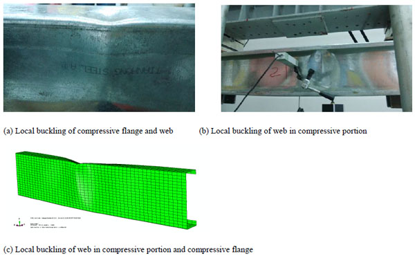
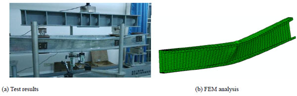
The tested lipped channel bending members typically failed with local buckling in the compressive flange and local buckling of web in the compressed portion (Fig. 5a and b) except specimens B900H140 which exhibited a combination of global lateral-torsional buckling of member and local buckling of compressive flange and web in the compressed portion, as shown in Fig. (6a).
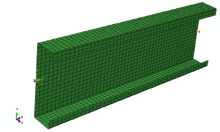
Moment-curvature diagrams captured in test are plotted between the bending capacity and the rotation angle in Figs. (7 and 8). The rotation angle is calculated according to the displacement of the specimen observed at 1/4 and 1/2 points of the pure portion.
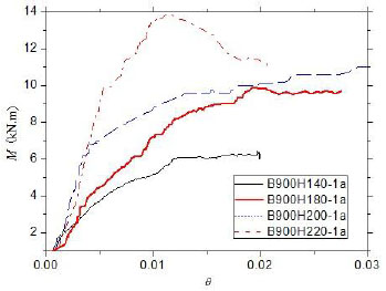
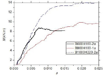
Fig. (7) depicts the moment–curvature diagrams for four different sections with a same effective length. The differences of their capacities indicate the bending moment capacity increases with the increase of the moment of sections when the bending members are in a same pure bending length. The curve demonstrates that the stiffness in inelastic stage for bending members becomes stronger as the increase of the moment of sections.
Fig. (8) shows the moment–curvature curves for three specimens in the different sections and effective length. Although the moment of section of specimen B600H160-2a is less than that of specimen B900H180-1a and B1000H220-2a, the stiffness is bigger than specimen B900H180-1a and approximates to specimen B1000H220-2a. This observation suggests that the global relative slenderness ratio has a significant impact on the stiffness of bending members because the global relative slenderness ratio of section B600H160-2a is close to that of section B1000H220-2a and more than that of section B900H180-1a.
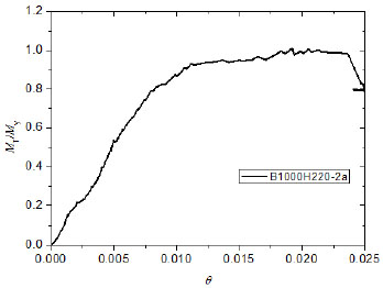
Fig. (9) showed the test result to the elastic yield moment ratio explains the loaded process of the bending member from elastic to inelastic and failure stage, using specimen B1000H220-2a as an example. The section is fully effective as an elastic member when the compression flange is under the small compressive stress. When the local and/or distortional buckling occurs at the compressive flange, the compressive flange starts to become non-fully effective and the stiffness decreases slightly. With the increase of the moment, the compressed portion of the web starts to buckle. Then effective area of the section decreases increasingly and the stress and strain in the compressive flange reach the yield stress and yield strain. At last, the compressive strain in compressive flange and partly compressive web increases beyond the yield strain, and the partly compressive web reaches the yield stress. The member exhibits the inelastic reserve capacity. The increase of capacity is slower than the increase of curvature.
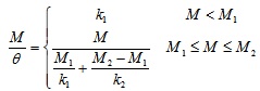
The moment-rotation curve of test specimens shows that there are two parts for these curves, which are the elastic and inelastic stages. To provide a model simple enough for the equations of moment-rotation of bending members a two-part linear model is explored for the moment-rotation response of cold-formed steel beams, elastic and inelastic stages. The parameters in the model are the elastic moment limit (M1) and the rotation corresponding to the elastic moment limit(θ1), the peak moment (M2) and the rotation corresponding to the peak moment (θ2). The elastic stiffness (ke) is assigned as the initial stiffness (k1) of the parameterized curve. The relationships of these parameters are shown in formulas (1) and (2).
 |
(1) |
 |
(2) |
So the equations of moment-rotation of bending members can be given using the formula (3).
 |
(3) |
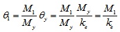
the rotation corresponding to the elastic moment limitθ1 can be calculated using formula (4).
 |
(4) |
Where θy is the rotation corresponding to the yield moment.
For θ2 a simple relationship is proposed as a function of buckling slenderness, which is shown as following:
 |
(5) |
For the elastic moment limit (M1) and the peak moment (M2) can be calculated using formula (6) and (7) based on test moment-rotation curve and design equation of effective width method.
 |
(6) |
 |
(7) |
Where
 fcr is the elastic buckling stress of bending members.
4. FINITE ELEMENT ANALYSIS
4.1. Finite Element Model
The general finite element non-linear analysis program ABAQUS was used to simulate the inelastic experimental behavior of the lipped channel bending members.
The back-to-back lipped channel sections were used in a 4-point bending test. Because of the special steel connector in the ends and the load points of specimens, the rotations of top flanges were prevented. So an idealized finite element model was selected to analysis the buckling failure mode and ultimate load carrying capacities of specimens. The analysis model is the constant moment region of the specimens, which can be considered as a pure bending test. At the two ends of the member, the warping keeps constraint and the sections keep from uniform rotation.
The material model adopts directly the results of the tensile tests. The ideal elastic-plastic curve is used based on the experimental steel elastic modular and yield stress for simplify finite element analysis. Residual stresses, residual strains and cold-work effects were not considered.
The ABAQUS S9R5 shell element was used to model bending members. The element aspect ratio was kept below 3:1 for lips, flange, web, and corners along the length direction. In the cross-section, 6, 18, 2, and 2 elements was used for the flange, web, lip, and corner, respectively. The ABAQUS solution control employed was the modified Riks method and the arc length method.
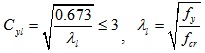
Imperfection sensitivity was considered in the finite element analysis. The value of the geometric imperfections adopted in analysis was L/750 according to Chinese cold-formed steel specification. The shape of the geometric imperfection was obtained from the first buckling mode shape of a finite element Eigen buckling analysis in ABAQUS. The finite element model for specimen is depicted in Fig. (10).
4.2. Buckling Mode and Capacity
The deformed shapes for the typical specimens obtained from the FEM analysis are presented in Figs. (5c and 6b), which is agree to the test failure mode depicted in Figs. (5a, b and 6a). This observation suggests that the idealized model can well model the buckling mode of the bending members.
The ultimate bending capacities (Mab) obtained from the FEM are compared with the test ultimate capacities (Mt) as shown in Table 2. Meanwhile, the bending capacities of every specimen calculated using Chinese cold-formed steel specification are shown in Table 2, Where MCI and MC are the bending capacity predicted using Chinese cold-formed steel specification with considering the interaction of the elements and without considering the interaction of the elements, Mey is the yield strength of bending members considering effective width. The mean value of the ratio of experimental-to-FEM ultimate bending capacities is 1.04 and the coefficient of variation is 0.0347 for all bending specimens. The comparison of ultimate capacity demonstrates that the ultimate bending capacity obtained from the FEM is close to the experimental ultimate capacity and the idealized model can also analyze the ultimate bending capacity well.
| Specimens | Mt(kN.m) | Mey(kN.m) | Mab(kN.m) | MCI(kN.m) | MC(kN.m) | Mt/Mey | Mt/Mab | Mt/MCI | Mt/MC |
|---|---|---|---|---|---|---|---|---|---|
| B600H160-1a | 8.65 | 7.27 | 8.47 | 7.58 | 7.61 | 1.19 | 1.02 | 1.14 | 1.14 |
| B600H160-1b | 8.65 | 7.54 | 9.09 | 7.86 | 7.88 | 1.15 | 0.95 | 1.10 | 1.10 |
| B600H160-2a | 8.77 | 7.27 | 8.50 | 7.58 | 7.62 | 1.21 | 1.03 | 1.16 | 1.15 |
| B600H160-2b | 8.77 | 7.44 | 9.02 | 7.76 | 7.80 | 1.18 | 0.97 | 1.13 | 1.12 |
| B600H160-3a | 9.04 | 7.52 | 9.01 | 7.84 | 7.88 | 1.20 | 1.00 | 1.15 | 1.15 |
| B600H160-3b | 9.04 | 7.33 | 8.66 | 7.65 | 7.69 | 1.23 | 1.04 | 1.18 | 1.18 |
| B600H180-1a | 9.78 | 8.29 | 9.53 | 8.64 | 8.75 | 1.18 | 1.03 | 1.13 | 1.12 |
| B600H180-1b | 9.78 | 8.32 | 9.62 | 8.67 | 8.79 | 1.18 | 1.02 | 1.13 | 1.11 |
| B900H140-1a | 5.83 | 5.42 | 5.68 | 5.35 | 5.30 | 1.08 | 1.03 | 1.09 | 1.10 |
| B900H140-1b | 5.83 | 5.25 | 5.54 | 5.31 | 5.26 | 1.11 | 1.05 | 1.10 | 1.11 |
| B900H140-2a | 5.75 | 5.36 | 5.71 | 5.42 | 5.37 | 1.07 | 1.01 | 1.06 | 1.07 |
| B900H140-2b | 5.75 | 5.12 | 5.49 | 5.18 | 5.13 | 1.12 | 1.05 | 1.11 | 1.12 |
| B900H140-3a | 5.79 | 5.20 | 5.53 | 5.26 | 5.21 | 1.11 | 1.05 | 1.10 | 1.11 |
| B900H140-3b | 5.79 | 5.26 | 5.63 | 5.34 | 5.29 | 1.10 | 1.03 | 1.08 | 1.09 |
| B900H180-1a | 9.88 | 8.79 | 9.36 | 8.82 | 8.94 | 1.12 | 1.06 | 1.12 | 1.11 |
| B900H180-1b | 9.88 | 8.83 | 9.47 | 8.86 | 8.98 | 1.12 | 1.04 | 1.12 | 1.10 |
| B900H180-2a | 10.09 | 8.62 | 9.14 | 8.65 | 8.76 | 1.17 | 1.10 | 1.17 | 1.15 |
| B900H180-2b | 10.09 | 9.17 | 10.05 | 9.21 | 9.33 | 1.10 | 1.00 | 1.10 | 1.08 |
| B900H200-1a | 11.99 | 10.49 | 11.05 | 10.49 | 10.60 | 1.14 | 1.08 | 1.14 | 1.13 |
| B900H200-1b | 11.99 | 10.55 | 11.38 | 10.55 | 10.65 | 1.14 | 1.05 | 1.14 | 1.13 |
| B900H200-2a | 12.10 | 10.71 | 11.82 | 10.71 | 10.82 | 1.13 | 1.02 | 1.13 | 1.12 |
| B900H200-2b | 12.10 | 10.82 | 12.03 | 10.82 | 10.93 | 1.12 | 1.01 | 1.12 | 1.11 |
| B900H220-1a | 13.84 | 12.07 | 13.06 | 12.47 | 12.59 | 1.15 | 1.06 | 1.11 | 1.10 |
| B900H220-1b | 13.84 | 12.22 | 13.78 | 12.62 | 12.74 | 1.13 | 1.00 | 1.10 | 1.09 |
| B1000H200-1a | 12.53 | 10.64 | 11.78 | 10.64 | 10.75 | 1.18 | 1.06 | 1.18 | 1.17 |
| B1000H200-1b | 12.53 | 10.51 | 11.46 | 10.51 | 10.62 | 1.19 | 1.09 | 1.19 | 1.18 |
| B1000H220-1a | 14.15 | 12.54 | 13.04 | 12.54 | 12.65 | 1.13 | 1.09 | 1.13 | 1.12 |
| B1000H220-1b | 14.15 | 12.66 | 13.10 | 12.66 | 12.79 | 1.12 | 1.08 | 1.12 | 1.11 |
| B1000H220-2a | 14.21 | 12.82 | 13.17 | 12.68 | 12.81 | 1.11 | 1.08 | 1.12 | 1.11 |
| B1000H220-2b | 14.21 | 12.82 | 13.14 | 12.70 | 12.84 | 1.11 | 1.08 | 1.12 | 1.11 |
| Mean | 1.142 1 | 1.040 0 | 1.125 1 | 1.118 8 | |||||
| Variance | 0.040 1 | 0.036 1 | 0.030 1 | 0.026 6 | |||||
| Coefficient of variation | 0.035 1 | 0.034 7 | 0.026 7 | 0.023 8 | |||||
4.3. Buckling Stress
To provide a stress distribution of the bending member under the different loading stages including the yield moment, peak moment, and peak displacement, the moment–rotation response of cold-formed steel beam analyzed by Abaqus is depicted in Fig. (11). The bending moment applied to the specimen B900H140-2b is 4.96 kN.m, 5.55 kN.m and 3.8kN.m for each of the three cases, respectively. Fig. (12) shows the Misses stress and stress along longitudinal direction for the specimen B900H140-2b in three different stages.
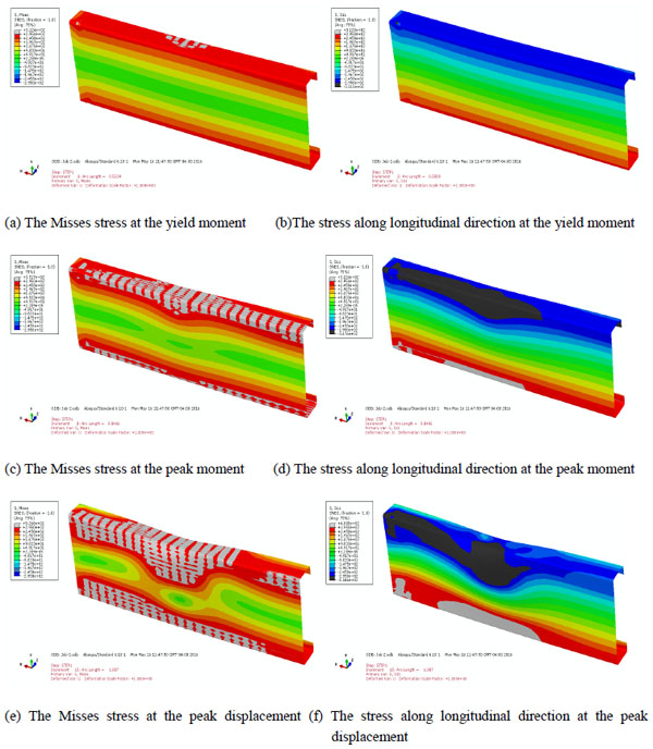
At the yield moment (Fig. 12a, b), the Misses stress and longitudinal stress of the flange reach the yield stress while the stress of the web is less than the yield stress. So the moment of member attains the yield moment. At the peak moment (Fig. 12c, d), the Misses stress and longitudinal stress of the flange reach the yield stress and the stress of the partially compressive web reaches the yield stress. This phenomenon shows that the inelastic reserve of the partially compressive web is worked and the ultimate moment is higher than the yield moment. Finally at the peak displacement (Fig. 12e, f), the Misses stress and longitudinal stress of the flange and the partially compressive web reach the yield stress and the maximum stress in the web is concentrate at the a small portion of member, which shows that the plastic hinge of beam occurs and the moment of member decreases increasingly.
5. COMPARISON OF TESTS AND DESIGN RULES
5.1. Chinese Cold-formed Steel Specification [5]
The strength and stability capacity should be calculated in Chinese cold-formed steel specification for bending members.
The strength of the bending member, M, is
 |
(8) |
Where Wen is the moment of the effective net section of the bending member.
The stability capacity of the bending member, Me, is
 |
(9) |
Where We is the moment of the effective section of the bending member φx, and is the global stability coefficient of the bending member.
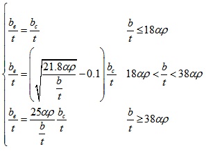
The relationship between the global stability coefficient (φx) and the global relative slenderness ratio
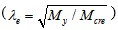 is depicted in Fig. (13). The maximum value of the global stability coefficient equals 1 which means that the bending capacity of members should be less than or equal the yield strength (My) of the bending members.
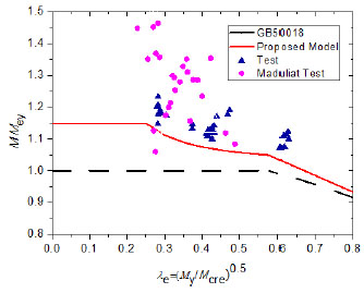
The effective width of elements can be calculated using following expression when the effective moment of section (We) need to be determined.
 |
(10) |
where b is the width of the element; t are the thickness of the element; be is the effective width of the element; bc is the compressive width of the element; α is a coefficient, and α=1.15-0.15ψ; ψ is an uneven coefficient of the compression stress distribution (for pure bending members, ψ=-1); ρ is a calculating coefficient,
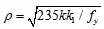 ; k is the buckling stability coefficient of the element; k1 is the interaction buckling coefficient of elements.
5.2. North America Cold-formed Steel Specification (Draft) [10]
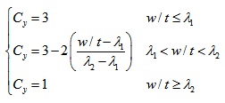
There are two existing methods to consider the inelastic reserve capacity in North American cold-formed steel specification (draft), which includes the Element-based method and DSM. The Element-based method is aligned with the EWM and only using the compression strain factor (Cy) varies from 1 to 3 to take into account the plasticity of compressive flange and partly compressive web. The compression strain factor can be predicted by using the following equation:
 |
(11) |
Where
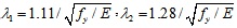 and w is the width of flange. The Element-based method can be also used to calculate the interaction of local buckling and yielding and global buckling.
The nominal strength considering inelastic flexural reserve capacity for DSM can be calculated as follows for global, local, and distortional buckling, respectively.
The expression of the inelastic global buckling capacity, Mnℓ, is:
For Mcre > 2.78My
 |
(12) |
Where Mcre is the critical elastic lateral-torsional buckling moment.
The inelastic local buckling capacity, Mnℓ is:
For λl ≤ 0.776
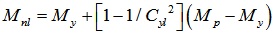 |
(13) |
Where
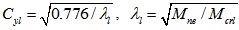 , Mne is the global buckling capacity defined as expression (12) and Mcrl is the critical elastic local buckling moment.
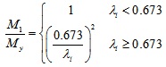
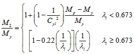
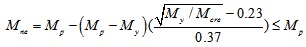
The inelastic distortional buckling capacity, Mnd, is:
For λd ≤ 0.673
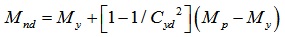 |
(14) |
Where
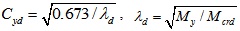 Mcrd is the critical elastic distortional buckling moment.
The inelastic bending capacity for the bending member is the minimum value calculated using expression (12), (13), and (14).
5.3. Comparison of Design Rules
The bending capacities of every specimen calculated using Chinese cold-formed steel specification, Element-based method, and DSM in North America cold-formed steel specification (draft) considering inelastic reserve capacity are provided in Tables 2 and 3, respectively, including ratios of test-to-calculated capacities using various design methods for each specimen, Where MNDSM is the ultimate capacity predicted using direct strength method (the minimum value of local buckling and distortional buckling capacity), and MNEWM is the bending capacity calculated using Element-based method. The mean value of ratios of test results to calculated bending capacities MCI and MC obtained using Chinese specification is 1.1251 and 1.1188, respectively. The comparison results indicate that the current Chinese cold-formed steel specification is too conservative to predict the inelastic bending capacity of bending members.
| Specimens |
Mt (kN.m) |
Mnl (kN.m) |
Mnd (kN.m) |
MNDSM (kN.m) |
MNEWM (kN.m) |
MCIP (kN.m) |
MCP (kN.m) |
Mt/ MNDSM | Mt/ MNEWM | Mt/MCIP | Mt/MCP |
|---|---|---|---|---|---|---|---|---|---|---|---|
| B600H160-1a | 8.65 | 8.21 | 8.14 | 8.14 | 8.36 | 8.53 | 8.56 | 1.06 | 1.03 | 1.01 | 1.01 |
| B600H160-1b | 8.65 | 8.50 | 8.61 | 8.5 | 8.69 | 8.88 | 8.90 | 1.02 | 1.00 | 0.97 | 0.97 |
| B600H160-2a | 8.77 | 8.21 | 8.42 | 8.21 | 8.32 | 8.55 | 8.59 | 1.07 | 1.05 | 1.03 | 1.02 |
| B600H160-2b | 8.77 | 8.40 | 8.40 | 8.4 | 8.55 | 8.76 | 8.80 | 1.04 | 1.03 | 1.00 | 1.00 |
| B600H160-3a | 9.04 | 8.49 | 8.52 | 8.49 | 8.62 | 8.86 | 8.91 | 1.06 | 1.05 | 1.02 | 1.01 |
| B600H160-3b | 9.04 | 8.27 | 8.32 | 8.27 | 8.41 | 8.63 | 8.67 | 1.09 | 1.07 | 1.05 | 1.04 |
| B600H180-1a | 9.78 | 9.36 | 8.55 | 8.55 | 9.51 | 9.69 | 9.82 | 1.14 | 1.03 | 1.01 | 1.00 |
| B600H180-1b | 9.78 | 9.35 | 9.66 | 9.35 | 9.74 | 9.66 | 9.80 | 1.05 | 1.00 | 1.01 | 1.00 |
| B900H140-1a | 5.83 | 5.62 | 5.97 | 5.62 | 5.93 | 5.60 | 5.54 | 1.04 | 0.98 | 1.04 | 1.05 |
| B900H140-1b | 5.83 | 5.44 | 5.91 | 5.44 | 5.89 | 5.56 | 5.50 | 1.07 | 0.99 | 1.05 | 1.06 |
| B900H140-2a | 5.75 | 5.50 | 5.98 | 5.5 | 6.01 | 5.68 | 5.62 | 1.05 | 0.96 | 1.01 | 1.02 |
| B900H140-2b | 5.75 | 5.32 | 5.78 | 5.32 | 5.75 | 5.41 | 5.36 | 1.08 | 1.00 | 1.06 | 1.07 |
| B900H140-3a | 5.79 | 5.39 | 5.86 | 5.39 | 5.84 | 5.49 | 5.44 | 1.07 | 0.99 | 1.05 | 1.06 |
| B900H140-3b | 5.79 | 5.47 | 5.96 | 5.47 | 5.93 | 5.57 | 5.52 | 1.06 | 0.98 | 1.04 | 1.05 |
| B900H180-1a | 9.88 | 9.63 | 8.86 | 8.86 | 9.59 | 9.45 | 9.58 | 1.12 | 1.03 | 1.05 | 1.03 |
| B900H180-1b | 9.88 | 9.66 | 8.88 | 8.88 | 9.76 | 9.48 | 9.61 | 1.11 | 1.01 | 1.04 | 1.03 |
| B900H180-2a | 10.09 | 9.44 | 8.53 | 8.53 | 9.55 | 9.24 | 9.36 | 1.18 | 1.06 | 1.09 | 1.08 |
| B900H180-2b | 10.09 | 9.93 | 9.80 | 9.8 | 10.33 | 9.86 | 9.99 | 1.03 | 0.98 | 1.02 | 1.01 |
| B900H200-1a | 11.99 | 11.22 | 10.93 | 10.93 | 11.83 | 11.23 | 11.35 | 1.10 | 1.01 | 1.07 | 1.06 |
| B900H200-1b | 11.99 | 11.22 | 11.10 | 11.1 | 11.84 | 11.30 | 11.41 | 1.08 | 1.01 | 1.06 | 1.05 |
| B900H200-2a | 12.10 | 11.45 | 11.25 | 11.25 | 12.07 | 11.48 | 11.59 | 1.08 | 1.00 | 1.05 | 1.04 |
| B900H200-2b | 12.10 | 11.57 | 11.45 | 11.45 | 12.16 | 11.61 | 11.73 | 1.06 | 1.00 | 1.04 | 1.03 |
| B900H220-1a | 13.84 | 12.95 | 12.38 | 12.38 | 12.59 | 13.52 | 13.65 | 1.12 | 1.10 | 1.02 | 1.01 |
| B900H220-1b | 13.84 | 13.10 | 12.53 | 12.53 | 12.74 | 13.68 | 13.82 | 1.10 | 1.09 | 1.01 | 1.00 |
| B1000H200-1a | 12.53 | 11.36 | 11.23 | 11.23 | 11.93 | 11.32 | 11.44 | 1.12 | 1.05 | 1.11 | 1.10 |
| B1000H200-1b | 12.53 | 11.19 | 11.03 | 11.03 | 11.79 | 11.17 | 11.28 | 1.14 | 1.06 | 1.12 | 1.11 |
| B1000H220-1a | 14.15 | 13.00 | 12.31 | 12.31 | 12.65 | 13.46 | 13.58 | 1.15 | 1.12 | 1.05 | 1.04 |
| B1000H220-1b | 14.15 | 13.21 | 12.53 | 12.53 | 12.79 | 13.60 | 13.74 | 1.13 | 1.11 | 1.04 | 1.03 |
| B1000H220-2a | 14.21 | 13.35 | 12.69 | 12.69 | 12.81 | 13.62 | 13.75 | 1.12 | 1.11 | 1.04 | 1.03 |
| B1000H220-2b | 14.21 | 13.43 | 12.63 | 12.63 | 12.84 | 13.62 | 13.78 | 1.13 | 1.11 | 1.04 | 1.03 |
| Mean | 1.0885 | 1.0334 | 1.0412 | 1.035 4 | |||||||
| Variance | 0.0399 | 0.0458 | 0.0306 | 0.030 8 | |||||||
| Coefficient of variation | 0.0367 | 0.0443 | 0.0293 | 0.029 8 | |||||||
The mean value of ratios of test results to calculated bending capacities using Element-based method considering inelastic reserve capacity in North America specification (draft) is 1.0334 and the coefficient of variation is 0.0443 for bending members. Meanwhile, the mean value of ratios of test results to calculated bending capacities using DSM considering inelastic reserve capacity in North America specification (draft) is 1.0885 and the coefficient of variation is 0.0367 for bending members. The comparison demonstrates that Element-based method and DSM in North America cold-formed steel specification (draft) well takes into account the increase on capacity because of inelastic reserve strength of the bending member. The DSM is more conservative and accurate than Element-based method.
6. PROPOSED DESIGN METHOD
The model proposal should be investigated based on the existing EWM in Chinese cold-formed steel specification in order to utilize the increase of capacity because of the effect of inelastic reserve capacity for the bending member.
6.1. Proposed Inelastic Capacity for Strength
In international cold-formed steel specifications, the compression strain factor (Cy) is usually used to consider the increase of moment because of inelastic reserve capacity, where the compression strain factor is the ratio of the ultimate strain to the yield strain and can be determined using expression (11). The partial plasticity shall be considered for the web of bending members in order to utilize the inelastic reserve capacity. Expression (11) means that the plastic height of web equals one third of the height of overall web when the flange is full effective. So the plastic height of web proposed for Chinese cold-formed steel specification can be determined using expression (15) based on expression (11) and EWM of Chinese cold-formed steel specification when the bending strength are calculated using formula (8).
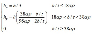 |
(15) |
The plastic strength of the lip of bending member is negligible in order to simplify calculation when the inelastic strength is calculated.
6.2. Proposed Inelastic Capacity for Stability
As shown in expression (16), the increasing of the global stability coefficient can increase the stability bending capacity. So the suggested method for stability capacity considering the inelastic reserve capacity can be put forward via increasing the global stability coefficient in inelastic stage. The global stability coefficient is increased at 1.15 and 1.05 when the global relative slenderness ratio equals 0.25 and 0.7, respectively. The revised curve for the global stability coefficient is depicted in Fig. (13).
The proposed global stability coefficient, φx, is
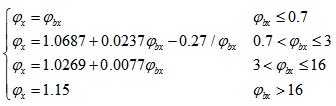 |
(16) |
Where φbx is the elastic global stability coefficient.
6.3. Comparison of Proposed Method
Fig. (13) compares the current Chinese design curve and the proposed design curve considering inelastic capacity based on EWM with the experimental results, in which effective section yield moment was used to determine the ratio of test-to-predicted results. Meanwhile, the test results performed by Maduliat, Bambach, and Zhao [11] are illustrated in the same figure. The comparison demonstrates that the proposed design method to predict the ultimate bending capacity is better than the existing Chinese method and less conservative.
The bending capacities of each specimen calculated using proposed method are provided in Table 3. MCIP and MCP are the bending capacity calculated using proposed method with considering the interaction of the elements and without considering the interaction of the elements, respectively. The mean value of ratios of test results to predicted results MCIP and MCP using the proposed method is 1.0412 and 1.0354 and the coefficient of variation is 0.0293 and 0.0298, respectively.
Meanwhile, the mean value of ratios of test results conducted by Maduliat, Bambach, and Zhao [11] to predicted results MCIP and MCP is 1.057 and 1.0699 and the coefficient of variation is 0.0742 and 0.0728, respectively. While the mean value of ratios of test results [11] to calculated results MCI and MC is 1.1568 and 1.1709 and the coefficient of variation is 0.0818 and 0.0804, respectively. The comparison indicates that the proposed method is less conservative. Additionally, the proposed method is slightly less conservative than DSM considering inelastic reserve capacity in draft of North America cold-formed steel specification.
Reliability analysis was performed in order to evaluate the appropriateness of the proposed effective width method to calculate the inelastic buckling load-carrying capacities for the cold-formed steel channel sections subjected to bending. The second-order moment method is used to estimate the design reliability of the bending member in this study. When the calculated reliability index (β) is larger than the target reliability index(β0), the proposed design method is regarded to be probabilistically safe. The target reliability index for cold-formed steel structural members is 3.2 according to the Chinese cold-formed steel specification.
The resistance of structural members is predicted by the following equation:
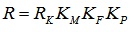 |
(17) |
Where RK is the characteristics value of the resistance of structural members; KM is the uncertainty of the material strength of structural members; KF is the uncertainty of the geometric characteristics of structural members; KP is the uncertainty of the calculation method.
Statistical parameters of the uncertainties of different kinds of external load in China can be obtained according to the existing research reference [15].
The load combinations of 1.2DL+1.4LL+0.84W as specified in the Chinese load specification were adopted in the calculation, where DL is the dead load, LL is the live load, and W is the wind load. The resistant partial coefficient for steel Q235 is taken as 1.087.The live load to dead load ratio used in calculation is 0.25, 0.5, 1, and 2. Based on the given resistance partial coefficient and calculation, the reliability indexes of the bending members are 4.1611, 4.2075, 4.1615, and 4.0207 for different load ratio and the mean value for reliability indexes is 4.1377 which is larger than the target reliability index(3.2). It is shown that the modified formulae of effective width method are accurate and reliable for bending members. Hence, proposed effective width method formulae (Eqs. (15)–(16)) are recommended for the design of cold-formed steel channel sections.
CONCLUSION
- The inelastic buckling test results on cold-formed lipped channel bending members have shown that the un-slender members display an important inelastic behavior, which results in that the moment capacities of bending members exceed the yield moment capacity of the bending member.
- The failure modes and ultimate bending capacities obtained from the FEM analysis are close to test results. This comparison indicates that the simply idealized finite element model can well analyze the buckling failure mode and ultimate capacity of cold-formed steel bending members.
- Current Chinese cold-formed steel specification has been verified to be too conservative for un-slender bending members due to the limit of the maximum value of capacity. Modifications about strength and stability capacity based on effective width method in Chinese specification have been proposed. Comparison between predicted results using proposed method and the test value demonstrates that the proposed method is less conservative. The proposed method provides a reliable and accurate calculation method for cold-formed steel lipped channel members in bending.
- The proposed method is slightly less conservative than DSM considering inelastic reserve capacity in draft of North America cold-formed steel specification.
CONFLICT OF INTEREST
The authors confirm that this article content has no conflict of interest.
ACKNOWLEDGEMENTS
The author gratefully acknowledgements the financial support provided by National Natural Science Foundation Projects of China (No: 51308277), Department of Science and Technology Natural Science Foundation Projects of Jiangxi Province in China (No: 20151BAB206055), and China Postdoctoral Science Foundation funded project (No: 2016M590382). The author really appreciates the professor Schafer B.W. in Johns Hopkins University who provided the suggestion and guidance.

