All published articles of this journal are available on ScienceDirect.
Overall Stability Analysis of Improved Buckling Restrained Braces
Abstract
In order to improve the behavior of double-tube buckling restrained braces (BRBs), it is proposed to set contact rings between inner tube and outer tube of the brace. As a result, they can provide lateral constraint for the inner tube; this is the improved buckling restrained braces (IBRBs). In this paper, a program was edited by the language of MATLAB based on theoretical model formulation of IBRBs and applied to the calculation of overall stability strength capacity. Finite element models of IBRBs were carried out and both load displacement curves and strength capacity were obtained. Tests on IBRBs were also conducted. The results of numerical simulation agreed with the ones of the program and tests. It indicated that the program was reasonable so it could provide a basis for the analysis of overall stability strength capacity of these kinds of IBRBs.
1. Introduction
Under rare earthquake actions, the braces in steel frames are easy to buckle so they will be out of action owing to a sharp decline in their stiffness and strength capacity. For this reason, the BRBs have been proposed. The outer tube restricts kernel, which can ensure the brace in elastic working stage under frequent earthquake actions and prevent overall buckling from prematurely occurring under rare earthquake actions. The BRBs can not only provide lateral stiffness, but also consume seismic energy by hysteretic behaviors of the kernel of the brace. BRBs overcome the shortcomings of traditional brace and have stable hysteretic energy dissipation performance and good fatigue capability. The traditional BRBs are generally composed of cross shaped and I-shaped section steel plate and the constraints are composed of concrete filled with steel tube. The study started in Japan; Fujimoto M, et al. [1] developed a kind of BRB, which is filled with mortar between outer steel tube and inner kernel. Theoretical analysis and test research were carried out and strength capacity and stiffness design criteria were obtained. Watanbe, et al. [2] put forward the relationship between elastic buckling strength of outer constraints and yield strength of inner tube based on the test of BRBs. Clark, et al. [3] studied the BRBs with cross section of inner tube, finding that the hysteretic behaviors of these kinds of BRBs were stable. However, the traditional BRBs have some drawbacks, such as the big connection length in the position of joints between the main structure and the splice plate, instability of plastic torsion, shortness of effective constraint region. Therefore, after then, the different types of all steel BRBs had been put forward. Cai ke-shuan et al. [4] in Taiwan developed a double-sleeve and double-kernel model of brace, and carried out theoretical analysis and test. The results showed that, when the frame reach the maximum lateral displacement angle, tensile strain of inner kernel of the brace would be greater than compressive strain of adjacent braces. Double-tube BRB is the displacement dependent energy dissipation damper [5]. However, it still has some drawbacks: 1) In order to make full use of energy dissipation of inner tube, clearance should be set between inner tube and outer tube. Owing to the existence of clearance, construction difficulties have been increased, and uniform distribution of clearance can hardly be achieved. Thus, the energy dissipation ability will be decreased. 2) Local buckling occurs easily in the joints of the brace and the structure. 3) Research results [5] show that, there is no obvious effect on the improvement of its strength capacity. Therefore, based on the research of double-tube buckling restrained braces, it is proposed to set one or several steel rings, which are called contact rings, between inner tube and outer tube. These are the improved buckling restrained braces (IBRBs) [6, 7]. The characteristics are: 1) the weight of the IBRBs with the material of steel is lighter compared with the concrete, and easy to process. 2) The clearance between inner tube and outer tube is the thickness of contact rings, this construction can ensure the energy dissipation of inner tube. 3) The contact rings at both ends will improve the rigidity and stability of inner tube, and avoid the problems of plastic torsional buckling and local buckling. 4) The IBRBs are composed of common steel, and are also suitable for long-span spatial structure. The inner tube of BRBs is generally low yield point steel [8-11], which has no large-scale domestic production. Therefore, it is necessary to make use of the existing steel. In this paper, theoretical research on the overall stability strength capacity of IBRBs was conducted and the finite element analysis and test study had been carried out to verify the theoretical analysis. The three results approximately agreed with each other.
2. The stability analysis of IBRBs
2.1. Design Methodology of the Specimens
2.1.1. Sectional Area of Inner Tube of BRBs
Fig. (1) shows the schematic of a structure, in which the BRBs are designed to resist all lateral loads. The columns and beams are designed for gravity load and the force transferred from brace, so that they remain elastic during the earthquake. It is intended that the maximum roof displacement is almost the same with the given target displacement. The lateral stiffness of BRB of the single story structure is derived as follows:
 |
(2.1) |
Thus,
 |
(2.2) |
The lateral stiffness of BRB is
 |
Where E is young's modulus, A is the sectional area of inner tube, θ is the slope.
Define nominal rigidity ratio as Rs = KD/Kf . KD is the lateral stiffness of BRB. Kf is the lateral stiffness of steel frame and the recommended value of Rs is between 3 to 5. The lateral stiffness of steel frame is obtained by D-value method with Kf = 12αEcIc/h3, α is correction coefficient with the derivation in Table 1. Ec is young's modulus of the column, Ic is the moment of inertia of the column. h is the height of column.
Derivation of correction coefficient
| Floors | Schematic of the structure | Beam-column stiffness ratio | Correction coefficient of stiffness |
|---|---|---|---|
| The ground floor |  |
 |
 |
| The other floors |  |
 |
 |
Notes: i1, i2, i3 and i4 are the linear stiffness of beam which can be deviated by the formula of i = EI/l. E is young's modulus of the beam, I is the moment of inertia of the beam. l is the length of beam.
From the statement above, the sectional area of inner tube of BRB can be obtained, that is
 |
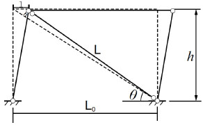
Schematic structure with BRB.
2.1.2. The Clearance Between Inner Tube and Outer Tube
Assume that the clearance between the core element and the constraint element is approximately zero when the structure of the interlayer deformation is 1.5 times of the maximum elastoplastic layer displacement.
According to code for seismic design of building structures in China, the elastoplastic deformation limit of the steel frame is h/50, h is height of column. the axial displacement of BRB is
 the Poisson’s ratio is v = ε'/ε, ε' is the transverse strain of inner tube of BRB, ε' = Δd/d, ε is the axial strain of inner tube of BRB, ε = Δl/l, d is the length of inner tube. So the deformation of BRB is Δd = 0.0045dsin2θ. Thus, the minimum clearance value between inner tube and outer tube can be obtained.
2.1.3. Sectional Area of Outer Tube of BRBs
The inner tube is combined tightly with outer tube through contact rings. At initial stage, both inner tube and outer tube deformed together under axial compression so that the deformation of inner tube is agreed with outer tube at the midpoint. Assume that contact pressure of central contact ring is Q when inner tube and outer tube bending together. In the real structure, two ends of the brace are articulated with main body structure. The simplified calculation model is shown below (see Fig. 2). The differential equations [12] are based on small deflection theory of mechanics of materials. Balance equation of inner tube is:
 |
(2.3) |
E1 is the Young’s modulus of inner tube.
I1 is the moment of inertia of an area of inner tube.
v1 (x) is y axial displacement of inner tube
Q is external force by outer constraints
P is external axial force
Balance equation of constraint is :
 |
(2.4) |
E2 is the Young’s modulus of outer constraints.
I2 is the moment of inertia of an area of outer constraints.
v2 (x) is y axial displacement of outer constraints.
Substitute Eq. (2.4) into Eq. (2.3), Eq. (2.5) can be obtained :
 |
(2.5) |
Apply boundary conditions to Eq. (2.5), the overall critical load can be obtained as Eq. (2.6):
 |
(2.6) |
µ-represents the coefficient of calculation length, l represents the length of inner tube. When µ = 1.0 it illustrates that both ends are articulated, µ = 0.5 are fixed. However, in the real structure, µ is between 0.5 and 1.0.
In recent researches, scholars hold the opinion that the flexural stiffness of inner tube is far less than the flexural stiffness of outer tube. Compare E2I2 with E1I1, E1I1 could be ignored, the formula can be simplified as Eq. (2.7):
 |
(2.7) |
To make full use of energy dissipation of inner tube, the members of BRBs are required to bear the maximum axial force, the value is Pmax = fyA1. It is necessary that Pmax ≤ Pcr when considering the safety of stability of BRBs. Define ζ = Pcr/Pmax = π2E2I2/(πl)2fyA1, in theory, if ζ ≥ 1, overall buckling of the member will not occur, however considering the safety, ζ ≥ 1.5 is suggested. The value of I2 can be obtained, also, the sectional area of outer tube can be acquired.
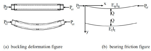
Figures of bearing friction of IBRBs.
The geometrical size and section parameter of IBRBs.
| Specimens | Length of member/cm | Member specification/mm | Stability strength capacity/kN |
||||
|---|---|---|---|---|---|---|---|
| Outer tube | Inner tube | Outer tube | Inner tube | Contact ring | |||
| Number | Specification | ||||||
| IBRBs-1 | 2.4 | 2.0 | Ф89×4.0 | Ф60×3.5 | 2 | Ф80×10.0 | 87.9 |
| IBRBs-2 | 2.4 | 2.0 | Ф89×4.0 | Ф60×3.5 | 3 | Ф80×10.0 | 129.1 |
| IBRBs-3 | 2.4 | 2.0 | Ф89×4.0 | Ф60×3.5 | 5 | Ф80×10.0 | 138.5 |
| IBRBs-4 | 2.4 | 2.0 | Ф76×4.0 | Ф60×3.5 | 5 | Ф68×4.0 | 136.4 |
| IBRBs-5 | 2.4 | 2.0 | Ф108×4.0 | Ф60×3.5 | 5 | Ф100×20 | 137.2 |
2.2. Geometrical Parameter
According to the above statement, it indicates that IBRBs in the condition of reasonable design can have good energy dissipation ability. Because of the limitation of equipment, reduced scale test was done by us. Geometrical parameters of IBRBs are shown in Table 2 and Fig. (3).
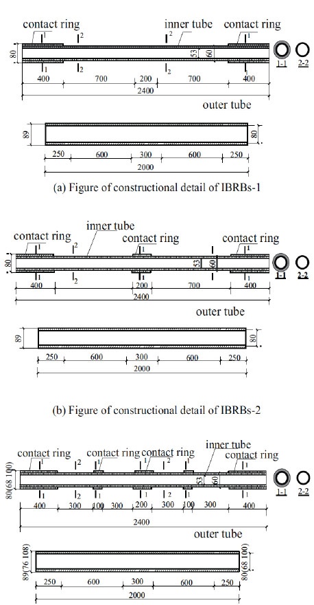
Figure of constructional detail of different IBRBs.
2.3. Theoretical Analysis
After development of the deformation of inner tube, it will be constrained by outer tube. Assume outer tube is in elastic stage, it provides inner tube with some equivalent force (see Fig. 4). The force depends on the deformation of outer tube and geometric parameters. When the number of the spring approaches to infinite, it equals to the double-tube without clearance. When the number of the spring is finite, it refers to the IBRBs. However, some more assumptions should be considered. 1) Both ends of the brace are articulated and the brace is considered as axially loaded member; 2) the outer tube is considered as elastic model and inner tube is considered as elastoplastic model; 3) the contact rings and outer tube are considered as springs, with the stiffness of ki.
Assume that each contact ring provides inner tube with stiffness ki and the stability strength capacity can be obtained according to the energy theory. The derivation can be expressed as Eq. (2.8):
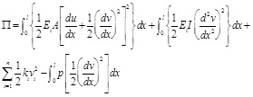 |
(2.8) |
In the formula, Ei is elastic modulus, when σx < fy, Ei equals E, when σx ≥ fy, Eiequals 0;
ki is the ith stiffness coefficient of the spring
vi is y axial displacement of the ith spring
u is x axial displacement of inner tube
v is y axial displacement of inner tube
x is the external load
In local system, Eq. (2.8) can be expressed as Eq. (2.9),
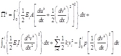 |
(2.9) |
Due to the axial displacement has little effect on the whole system, it can be omitted. The formula can be expressed as:
 |
(2.10) |
The incremental displacement of the element in local coordinate can be expressed as:
 |
(2.11) |
The node incremental displacement and shape function matrix in local coordinate are:
 |
(2.12) |
 |
(2.13) |
 |
(2.14) |
The relationship of the incremental displacement of the element between local coordinate and global coordinate is:
 |
(2.15) |
In which,
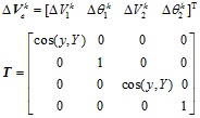 |
Discrete Eq. (2.10), Eq. (2.16) can be obtained.
 |
(2.16) |
In which,
 |
Consider the relationship between local system and whole system, set
 |
Then, the whole system can be expressed as Eq. (2.17)
 |
(2.17) |
For δΠk=0, the differential calculus of Eq. (2.17) is Eq. (2.18)
 |
(2.18) |
In Eq. (2.18), the last item is the part of spring. This item can also be expressed as a column vector where the nodes ki with springs has non zero value and the others without springs have zero values. Thus,
 |
(2.19) |
The characteristics is that V ≠ 0, Thus | K-pM + kik | = 0, the minimum value of p is the value of stability strength capacity.

Brief figure of the inner tube of IBRBs.
According to the above process, a program can be applied by using MATLAB; this program can calculate the values of stability strength capacity of different IBRBs. The values are listed in Table 1.
3. Finite element analysis of IBRBS
3.1. Models of the IBRBs
The model is established by using the ANSYS finite element analysis software. Solid45 is applied to the inner tube, outer tube and contact rings of IBRBs. There is a large room of contact area between inner tube and outer tube. Conta174 which has high order quadrilateral element of 8 nodes is adopted. For the displacement of structure will cause nonlinear structure. The comprehensive yield strength of inner tube is 235Mpa. The yield strength of outer tube is 235Mpa, employing steel Q235 with 0.3 elastic modulus. Mapped meshing method and displacement load method are applied, both ends are articulated. The figures of different IBRBs are as Fig. (5).
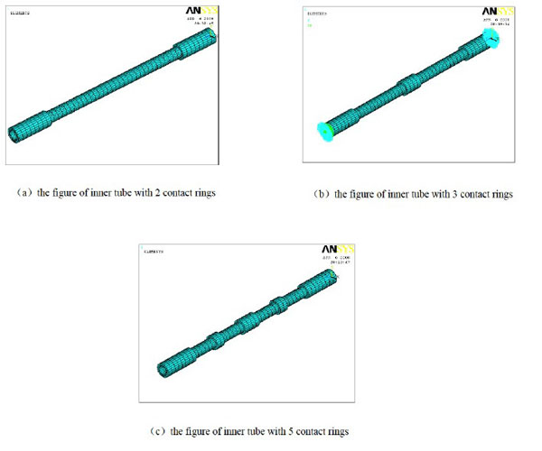
Figure of finite element model.
3.2. Strength Capacity Analysis
Generally, the strength capacity of the member mainly depends on its geometry and material. As for the IBRBs, inner tube is under constraint of outer tube and the strength capacity has been significantly improved. The main factors are: 1) The number of contact rings; 2) The restraining stiffness; 3) Geometric imperfection.
3.2.1. The Effect of the Number of Contact Rings
Through tracking one-way loading of IBRBs-1, IBRBs-2 and IBRBs-3, the load displacement curves (see Fig. 6) and the calculation results (see Table 3) can be obtained.
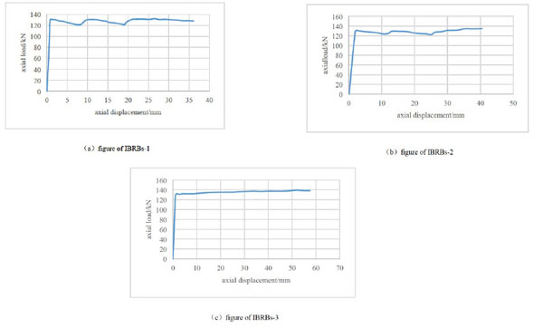
Axial load displacement curves.
(1) The curves can be divided into two stages. Namely, elastic stage, which is from the beginning to the first turning point, and plastic stage, which is from the first turning point to the end. In the plastic stage, the curve is smooth, assuming it as a flat line. Therefore, the model can be simplified as an ideal elastoplastic model.
(2) The yield strengths of the members are respectively: 124.8kN, 126.4kN and 128.6kN with the increase of contact rings. It shows that the effect of contact ring is good and can improve the yield strength.
(3) After the development of the four curves reaching to the first turning point, there is a small fluctuation on the curves with the increase of the number of contact rings. The member of IBRBs-1 has the greatest curve fluctuation and the load has a downward trend. However, the curves of IBRBs-2 and IBRBs-3 have a remarkable rising trend. The stability of IBRBs-3 is good and fully meets the standard of ideal plasticity.
Table of calculation results.
| Number | Yield strength Pu/kN | Ultimate strength Pu/kN | Clearance/mm | Number of contact ring |
|---|---|---|---|---|
| IBRBs-1 | 124.8 | 131.6 | 10 | 2 |
| IBRBs-2 | 126.4 | 135.3 | 10 | 3 |
| IBRBs-3 | 128.6 | 142.5 | 10 | 5 |
3.2.2. Effect of Restraining Stiffness
The strength capacity of the brace is influenced by the restraining stiffness. However, owing to the clearance between inner tube and outer tube, the inner tube is under fewer constraints in the process of initial load. The larger the clearance distance is, the larger the deformation is. As a result, it can cause the decrease of strength capacity. Owing to the effect of restraining stiffness; the clearance should be taken into consideration. Now combine the stiffness ratio with the clearance, comprehensive restraining stiffness coefficient η can be applied. Stiffness ratio is ζ = Pcrta/Py, flexural rigidity EI which is proportional to the strength capacity can be applied to simplify the stiffness ratio. The clearance c is in inverse proportion to the strength capacity. Thus, comprehensive restraining stiffness coefficient is η' = ζ/c
 η = EI/c
From the calculation results of Table 4, following conclusions can be obtained:
Table of the calculation results.
| Specimens | Stiffness of outer tube E/KN ∙ m2 | Yield strength Py/KN | Ultimate strength Pu/KN | Clearance /mm |
Comprehensive restraining stiffness coefficient η | Number of contact ring |
|---|---|---|---|---|---|---|
| IBRBs-3 | 196.3 | 128.6 | 142.5 | 10.0 | 19.6 | 5 |
| IBRBs-4 | 121.1 | 127.7 | 153.5 | 4.0 | 30.3 | 5 |
| IBRBs-5 | 364.5 | 131.2 | 132.6 | 20.0 | 18.2 | 5 |
(1) With the development of the restraining stiffness, the yield strengths of three members are increased from 127.7kN to 131.2kN. Due to the load at initial stage, the deformation of the inner tube is mainly the axial deformation. At this time, the contact ring is closely combined with outer tube. So the greater the constraint ability is, the better the strength capacity is.
(2) The ultimate strengths of three members are increased from 132.6kN to 153.5kN. As if the ultimate loads are decreased with the increase of restraining stiffness, this strange phenomenon mainly lies in the clearance. The larger the clearance is, the more decline of the constraint ability is. All things considered, the ultimate strength becomes larger with the development of the comprehensive restraining stiffness. According to the results of finite element analysis, in order to make full use of energy dissipation capacity of inner tube, the comprehensive restraining stiffness coefficient should be guaranteed in an appropriate value.
(3) The ultimate strength of the three members exceed the yield strength. It shows that the strength capacity of BRBs with contact rings has been enhanced.
3.3. Analysis of Load Displacement Curve
Through the calculation of restraining stiffness of the three members, three curves (see Fig. 6 and Fig. 7) could be obtained. In general; the curve of IBRBs-5 has a poor stability. In contrast, the curves of IBRBs-3 and IBRBs-4 are stable.
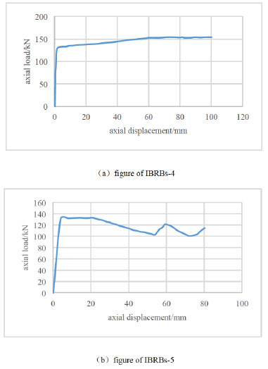
The displacement curves of one way loading.
(1) The development tendency of IBRBs-3, IBRBs-4 and IBRBs-5 agreed with each other. They are all in the ideal linear period. The initial stiffness of the three members has a little difference, for it mainly reflects the stiffness of inner tube at the initial stage.
(2) The curves of the three members from the yield point to the displacement reaching to 20mm are relatively stable. It means they are all in the plastic stage with mainly axial deformation.
(3) After the displacement of 20mm, the strength capacity of IBRBs-3 and IBRBs-4 have been enhanced. They are all in the strengthening stage. However, the strength capacity of IBRBs-5 is unstable. It means that the member has been affected by the outer tube. For the comprehensive restraining stiffness coefficient η is large and the clearance is small, with deformation of inner tube well constrained by outer tube. Thus, the continuing development is stable. The comprehensive restraining stiffness coefficient η of IBRBs-5 is small and the clearance is large, so the constraint can hardly meet the deformation of inner tube. As a result, the constraint effect is declined and the curve is fluctuated.
(4) After the displacement of 60mm the curve is a horizontal line, IBRBs-3 and IBRBs-4 reach to their ultimate strength.
4. Test verification
4.1. The Test Load Program
The loading device consists of a rigid base and loading portal frame (see Fig. 8). The test adopts one way loading and cyclic loading. In order to check the experimental apparatus and data acquisition system, 1.5mm preload should be applied for the specimen before loading. After then, 3 specimens are under one way loading and cyclic loading, the load should be terminated under these following circumstance:
(1) Overall buckling of the brace.
(2) Insufficient rigidity of constraint leads to higher order buckling instability.
(3) Crack of weld seam between flanges and brace.
(4) Fracture of the end of inner tube.
Considering the strength capacity of the loading device and the load program of exiting test, displacement load method is adapted for the whole loading process. Before the value of 100kN, the incremental displacement is 1.5mm, when the value exceeds 100kN; the incremental displacement is 1mm, each stage of load cycling once.
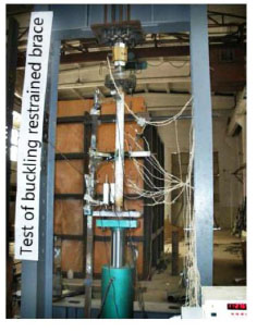
Test loading device.
4.2. The Arrangement of Survey Points
There is a load sensor arranged between the upper flanges plate and the load beam (see Fig. 9). The arrangements of displacement meter are:
(1) One is arranged at the upper flanges, mainly to determine the out of plane lateral displacement.
(2) Three of them are distributed along the trisection of circumference of outer tube.
(3) Two of them are arranged at the brace of bottom flanges, mainly to measure axial displacement. Strain gauges (see Fig. 9) are distributed along the position of the trisection of circumference of the steel tube; with a strain gauge set in each position. Thus, three strain gauges are arranged in each section.

The arrangement of strain gauge.
4.3. Strength Capacity Analysis
Table 5 lists the main information of the test and Fig. (10) is the load displacement curve. Following conclusions can be obtained.
Results of bearing capacity and displacement.
| Number | Maximum axial displacement/mm | Bearing capacity of inner tube in yield form/kN | Bearing capacity when yield/kN | Maximum bearing capacity/kN | Maximum lateral displacement/mm |
|---|---|---|---|---|---|
| IBRBs-3 | 54.5 | 147.3 | 147 | 171 | 1.0 |
| IBRBs-4 | 54.0 | 147.3 | 146 | 169 | 1.4 |
| IBRBs-5 | 54.5 | 147.3 | 149 | 164 | 0.5 |
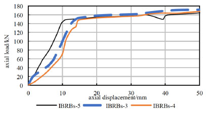
The load displacement curve.
(1) The yield strengths of IBRBs-3, IBRBs-4 and IBRBs-5 are close to each other. On the whole, the yield strength increases with the increase of restraining stiffness. Because at the initial stage, the main deformation is the axial deformation and the contact ring is closely combined with outer tube. The grater the constraint of outer tube is, the better the strength capacity is. The strength capacity is proportional to the constraining stiffness. Compared with the finite element numerical calculation results, the test results are relatively large, because the value of yield strength in reality is larger than that in theory. However the main principles between them are the same.
(2) In the process of the test, the three members of lateral displacement are very small and the maximum lateral displacement is 2.1mm. The deformation of the member is 1.75‰ of its length. It means overall buckling doesn't occur. The test value of strength capacity has exceeded the calculated value of yield strength (see Table 5). In view of the results, the inner tube is on yield form. That means it reaches to the goal that the buckling restrained brace of the tube is on yield form without buckling.
4.4. Hysteretic Loops Analysis
The hysteretic loops of the specimens under cyclic loading are shown in Fig. (11). The weld in IBRBs-5 was cracked due to the poor quality in the test and the core of the member wasn’t in plastic stage. Thus, the figure of IBRBs-5 hasn’t been presented below. The load and displacement loop is plump and fusiform shaped so that specimen energy dissipation is good. Hysteresis loops show:
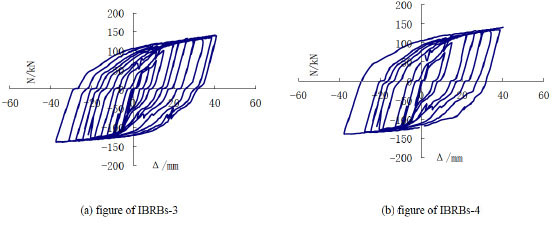
The hysteretic curves.
(1) The shapes of the hysteresis loops of both IBRBs-3 and IBRBs-4 are similar with each other, they have basically the same envelope area and the same energy dissipation ability.
(2) The hysteresis loops without big fluctuations and strength degradation are plump. The reason is that, with the increment of contact rings, the outer tube plays an important role in constraining the inner tube so that it will yield without buckling, reaching to the effect of same performance in compression and tension.
4.5. The Strength Back-Bone Curves
The strength back-bone curves of IBRBs-3 and IBRBs-4 are shown in Fig. (12). As can be seen from the figure:
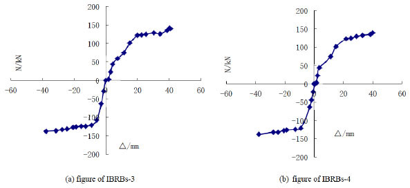
The skeleton Curves.
(1) The maximum load in tension and compression of IBRBs-3 and IBRBs-4 are similar with each other.
(2) The compression and tension curves of IBRBs-3 and IBRBs-4 are relatively smooth.
(3) The shape of the strength back-bone curves by cyclic loading is similar with the curve of the one way loading, however, the maximum load is slightly lower.
5. Comparison
As can be seen from Table 6, comparing theoretical stability strength capacity with the ones of bearing strength of simulation and bearing strength of test, only the value of theoretical stability strength capacity of IBRBs-1 can’t meet the engineering accuracy requirement compared with others. The reason mainly lies in that, as can be seen in Fig. (3) (the IBRBs-1 with two contact rings at both ends), there are no supports such as the equivalent springs of K1,K2…(middle contact rings) in the middle so only first order mode occurs. As a result, the value of 87.9kN is only just a reference value. However, compared with the classical Euler formula, the program of the overall stability capacity without contact rings in the middle is reliable. For the value of 87.9kN coded by MATLAB closely equals Euler critical load with the value of 87.7kN. Due to the constraint by equivalent springs, high order mode will occur. Thus, theoretical stability strength capacity can reach to the values of numerical simulation and test. For the numerical simulation, with the increment of contact rings, the yield strength has been improved with smaller fluctuation. With the larger clearance of IBRBs-5, the constraint can hardly meet the deformation of inner tube. Consequently, the constraint effect is declined and the curve is fluctuated. However, they are basically in line with the test results and numerical simulation.
(1) Comparing simulation with test results, the tendency of the load displacement cures are basically agreed with each other; theoretical and numerical simulation match well with the test.
(2) Comparing results of yield strength of simulation with theoretical strength capacity, the values of the theoretical results of IBRBs-2 and IBRBs-3 are 2.14% and 7.7% larger than the values of numerical simulation respectively. Compare bearing strength of test with theoretical results, the values of the theoretical results of IBRBs-3, IBRBs-4 and IBRBs-5 are respectively 5.78%, 6.58% and 7.92% lower than the test.
(3) Comparing theoretical results with yield strength of simulation and yield strength of test results, theoretical results meet the engineering accuracy requirement. Thus, the program is feasible.
| Specimens | Euler critical load kN | Theoreticalstability strength capacity/kN | yield strength of simulation/kN | Ultimate strength of simulation/kN | Bearing strength of test/kN | Ultimate strength of test/kN |
|---|---|---|---|---|---|---|
| IBRBs-1 | 87.7 | 87.9 | 124.8 | 131.6 | - | - |
| IBRBs-2 | 87.7 | 129.1 | 126.4 | 135.3 | - | - |
| IBRBs-3 | 87.7 | 138.5 | 128.6 | 142.5 | 147 | 171 |
| IBRBs-4 | 87.7 | 136.4 | 127.7 | 153.5 | 146 | 169 |
| IBRBs-5 | 87.7 | 137.2 | 131.2 | 132.6 | 149 | 164 |
Conclusion
(1) The results of theoretical calculation and the ones of numerical simulation and test are close with each other. The maximum deviation is 7.92%; fully meeting the requirements of engineering accuracy. The derivation of simplified calculation mode of IBRBs based on energy theory is reliable. The programming calculation of overall stability strength capacity using MATLAB can be obtained directly, which is convenient for calculation.
(2) Through numerical simulation and test verification, strength capacity is acquired. The main factors affecting the strength capacity are the number of contact rings and the restraining stiffness. The overall stability of IBRBs has been improved with the increment of contact rings. With the function of restraint, the member yield without buckling under the action of both compression and tension.
(3) The finite element analysis agreed with the text results and the whole member has good energy dissipation ability.
CONFLICT OF INTEREST
The authors confirm that this article content has no conflict of interest.
ACKNOWLEDGEMENTs
This research is supported in part by National NSFC (Natural Science Foundation of China) (50678078), Basic Research Foundation of Colleges and Universities of Gansu Province.


