All published articles of this journal are available on ScienceDirect.
Cracking Resistance of Reinforced SFRFLC Superposed Beams with Partial Ordinary Concrete in Compression Zone
Abstract
A new reinforced SFRFLC (abbr. steel fiber reinforced full-lightweight concrete) superposed beam was proposed to sufficiently utilize the good peculiarities of ordinary concrete in compression and SFRFLC in tension, and reduce its self-weight. Experimental study was carried out on the flexural behaviors of reinforced SFRFLC superposed beams compared with reinforced concrete beams and reinforced SFRFLC beams, the effects of such factors as sectional depth of SFRFLC, volume fraction of steel fiber, longitudinal tensile reinforcement ratio and strength of ordinary concrete were analyzed. Based on the composite principle, formulas are proposed for calculating the cracking resistance of reinforced SFRFLC superposed beam and the reasonable sectional depth of SFRFLC. The results showed that there was the optimal sectional depth of SFRFLC, steel fiber was the main factor while high-strength ordinary concrete and proper reinforcement ratio were beneficial to enhance the cracking resistance of reinforced SFRFLC superposed beam.
1. INTRODUCTION
Steel fiber reinforced lightweight-aggregate concrete (SFRLC) is a relatively new structural material developed by adding short steel fibers oriented randomly in lightweight-aggregate concrete, which has good peculiarities of tensile performance [1, 2], compressive ductility [3, 4] and impact resistance [5]. To further lighten the self-weight of concrete, by using sintered expanded shale as lightweight coarse and fine aggregates, steel fiber reinforced full lightweight-aggregate concrete (SFRFLC) for structural application was also developed [6, 7]. Several studies were carried out to verify the flexural behaviors of reinforced SFRLC beams, where influencing factors such as volume fraction of steel fiber [8, 9], strength of concrete [9, 10], longitudial tensile reinforcement ratio [11] and depth to shear-span ratio [12] were considered. These demonstrated that the significant roles of steel fibers are restraining the formation and growth of cracks, and carrying the released tensile stress from cracked concrete. Similar to the technique called layered beam [13], by using the ordinary concrete in compression zone to improve the flexural behavior of reinforced SFRFLC beams, a new kind of cast-in-place reinforced SFRFLC superposed beam was developed [14, 15]. The purposes of this innovation are to comprehensively utilize the good peculiarities of ordinary concrete subjected to compressive stress and SFRFLC undertaken tensile stress, and to lighten the self-weight of concrete structures as much as possible. This will be much more suitable to the construction of long-span structures bearing vertical loads.
To throughly study the flexural behaviors of reinforced SFRFLC superposed beams, a series of tests were carried out [15]. This paper focuses on the cracking resistance of these beams, and gives the calculating method for the design of reinforced SFRFLC superposed beams.
2. EXPERIMENTAL STUDY
2.1. Test Beams
Test beams were rectangular section in dimensions of width b=150 mm and depth h=300 mm, and length L=3 m. For each beam, two longitudinal tensile rebars were used as reinforcement in the tensile zone, 2ϕ10 rebars in the compression zone and ϕ 8@100 mm stirrups in the shear-span were used as the constructional reinforcements. The longitudinal tensile rebars were 14 mm, 18 mm, 20 mm, 22 mm and 25 mm in diameter, respectively, corresponding to the longitudinal tensile reinforcement ratio (ρ) as 0.77%, 1.28%, 1.58%, 1.92% and 2.49%. Their mechanical properties are listed in Table 1. The thickness of concrete cover for longitudinal tensile rebars was 25 mm. As shown in Fig. (1), the sectional depth (h1) of SFRFLC changed from zero to 300 mm (where h1=0 corresponding to ordinary reinforced concrete beam and h1=300 mm corresponding to reinforced SFRFLC beam), the volume fraction of steel fiber (ρf) of SFRFLC ranged in 0~1.6%,
| Rebar | Diameter (mm) |
Yield strength fy (MPa) |
Ultimate stregth fu (MPa) |
Elongation (%) |
|---|---|---|---|---|
| HRB400 | 14 | 480.8 | 617.3 | 14.3 |
| HRB400 | 18 | 451.9 | 564.2 | 23.3 |
| HRB335 | 20 | 404.2 | 520.4 | 22.5 |
| HRB335 | 22 | 344.7 | 581.4 | 24.8 |
| HRB335 | 25 | 392.1 | 520.5 | 23.6 |

Grade 42.5 and 52.5 ordinary silicate cements, crushed limestone with continuous grading of 5~20 mm particle size, natural sand with 2.86 fineness modulus, high-performance water reducer and tap-water were used for ordinary concrete. Grade 42.5 ordinary silicate cement, expanded shale, ceramisite sand, steel fiber, high-performance water reducer and tap-water were used for SFRFLC. Steel fiber was cut sheet type in dimension of 32 mm long and 0.6 mm equivalent diameter. References [6, 15] detailed the mix proportion of ordinary concretes and SFRFLCs. Their cubic compressive strength (fcu, ffcu), axial compressive strength (fc, ffc), tensile strength (ft, fft) and modulus of elasticity (Ec, Efc) are presented in Table 2.
Table 2 lists the series of test beams. The meaning of serial number is: strength of ordinary concrete (C**) or SFRFLC (LC**)-sectional depth of SFRFLC-diameter of longitudinal rebar-volume fraction of steel fiber, where a/b represents 2 beams in each group. The construction of test beams included steel reinforcement framework, formwork assembling, concrete mixing, casting and curing. The concrete cover was ensured by using four inverted U-shape rebar holders welded on the undersurface of longitudinal tensile rebars in shear-span segments. The steel formworks were used to ensure the dimensional precision within ± 3 mm. The SFRFLC was firstly cast as the designed depth after compaction, the ordinary concrete was cast on SFRFLC and compacted by vibrating needle which was controlled within 10 mm depth into SFRFLC to ensure the interface integrity. After 48 hours, the formwork was removed. The beams were cured by water spraying for 7 days, then placed indoors up to 28 days for testing. The basic mechanical properties of ordinary concrete and SFRFLC were tested by the standard cubes in dimension of 150 mm and prisms of 150 mm×150 mm×300 mm cast accompany test beams.
| No. of test beam | Ordinary concrere | SFRFLC | Influencing factors considered | ||||||
|---|---|---|---|---|---|---|---|---|---|
|
fcu (MPa) |
fc (MPa) |
ft (MPa) |
Ec (GPa) |
ffcu (MPa) |
ffc (MPa) |
fft (MPa) |
Efc (GPa) |
||
| C40-0-20-0a/b | 47.4 | 43.7 | 4.02 | 3.41 | — | — | — | — | Depth ratio of SFRFLC (h1/h) |
| C40-120-20-1.2a/b | 47.8 | 43.2 | 3.96 | 3.42 | 42.6 | 39.7 | 3.38 | 2.51 | |
| C40-150-20-1.2a/b | 47.8 | 43.2 | 3.96 | 3.42 | 42.6 | 39.7 | 3.38 | 2.51 | |
| C40-180-20-1.2a/b | 49.3 | 44.1 | 4.12 | 3.44 | 41.9 | 38.5 | 3.32 | 2.48 | |
| C40-210-20-1.2a/b | 49.3 | 44.1 | 4.12 | 3.44 | 41.9 | 38.5 | 3.32 | 2.48 | |
| LC30-300-20-1.2a/b | — | — | — | — | 41.9 | 38.5 | 3.32 | 2.48 | |
| C30-0-18-0a/b | 39.6 | 34.2 | 2.98 | 3.25 | — | — | — | — | Fraction of steel fiber by volume in SFRFLC (ρf) |
| C30-180-18-0.8a/b | 39.0 | 33.8 | 2.93 | 3.25 | 42.3 | 37.9 | 3.10 | 2.50 | |
| C30-180-18-1.2a/b | 39.6 | 34.2 | 2.98 | 3.25 | 41.9 | 38.2 | 3.28 | 2.48 | |
| C30-180-18-1.6a/b | 39.0 | 33.8 | 2.93 | 3.25 | 43.5 | 39.4 | 4.10 | 2.53 | |
| C30-210-14-1.2a/b | 38.6 | 33.4 | 2.90 | 3.22 | 43.4 | 39.8 | 3.43 | 2.53 | Longitudinal reinforcement ratio of tensile rebar (ρ) |
| C30-150-22-1.2a/b | 38.6 | 33.4 | 2.90 | 3.22 | 43.4 | 39.8 | 3.43 | 2.53 | |
| C30-120-25-1.2a/b | 38.6 | 33.4 | 2.90 | 3.22 | 43.4 | 39.8 | 3.43 | 2.53 | |
| C30-160-20-1.2a/b | 39.6 | 34.2 | 2.98 | 3.25 | 41.9 | 38.2 | 3.28 | 2.48 | |
| C40-210-18-1.2a | 49.0 | 44.0 | 4.08 | 3.44 | 41.9 | 38.2 | 3.28 | 2.48 | Strength grade of ordianry concrete (fc) |
| C60-230-18-1.2a/b | 69.0 | 55.4 | 4.32 | 3.70 | 41.1 | 37.2 | 3.25 | 2.46 | |
| C70-240-18-1.2a/b | 82.3 | 65.8 | 4.80 | 3.81 | 43.6 | 38.9 | 3.49 | 2.53 | |
2.2. Test Method
Third-point loading tests of the beams were carried out. The loading device was composited by the steel-frame and the hydralic jacks, the concentrated loads were measured and controlled by the load transducer on top surface of the beam, as shown in Fig. (2). The concrete strains at mid-span section were measured by the strain gauges and handheld deformeter with test points bonded on the side and top surfaces of the beam, the deflection was measured by the electrical displacement meters installed on the supports and mid-span of beam.
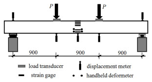
The load corresponding to the cracking resistance was determined under the comprehensive judgement as follows: (1) the initial cracks on the side surface of beam were not less than 2 in number, and elongated over the center of longitudinal tensile rebar; (2) the first point changing slope was on load-deflection curve of beam. The cracks were detected by the crack visualizer.
2.3. Overview of Test Results
According to the test data, the concrete strain distributed as linear along the depth of cross-section, the neutral axis moved from centroid axis to compressive edge with the increase of test load, resulting in the reduction of depth of compressive zone. As the ordinary concrete was subsequently cast-in-place on SFRFLC, the interface between them was well bonded without any slip being observed. The flexural capacity was mainly affected by the reinforcement ratio, and secondly affected by the compressive strength of ordinary concrete, the volume fraction of steel fiber and the sectional depth of SFRFLC [15, 16].
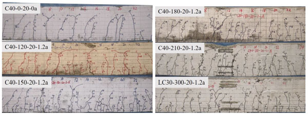
As shown in Fig. (3), compared with the reinforced concrete beam, the cracks distributed on reinforced SFRFLC superposed beams were smaller in space, short elongation, more secondary and rhizoid; with the increase of sectional depth of SFRFLC, the crack distributions of reinforced SFRFLC superposed beams were close to that of reinforced SFRFLC beams.
From Fig. (4), the crack space decreased with the increase of volume fraction of steel fiber, hence the crack width decreased under normal service loads correspondingly. Less effect of the increase of volume fraction of steel fiber was on the failure states of test beams.

From Fig. (5), with the increase of longitudinal tensile reinforcement ratio, the elongation of cracks shortened, the space of cracks reduced, and the crack width under normal service loads minimized. Meanwhile, the sectional depth of compressive zone increased, and the failure of compressive concrete took place normally on test beams after the yield of longitudinal tensile rebars.

From Fig. (6), less effect of the strength increase of ordinary concrete was on the crack distribution and elongation under normal service loads, while failure of test beams took place with lower compressive zone and larger crack width.

3. CALCULATION FORMULAS OF CRACKING RESISTANCE
Based on the researches [18, 19], the calculation of cross-sectional cracking resistance can be made by using the mechanics of materials for the reinforced concrete beam, where the sectional plasticity coefficient (γ) of elastic resistance moment is used to reflect the favorable effect of subsistent plastic deformation of concrete in the tensile zone of cross section. The formulas are
 |
(1) |
 |
(2) |
Where, Mcr is the sectional cracking resistant-moment of reinforced concrete beam; ft is the tensile strength of ordinary concrete; W0 is the elastic resistance moment to tensile edge of transformed section; h is the sectional depth.
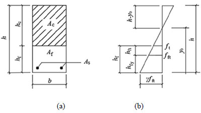
As stated above, no slip were visually observed regarding the interface between ordinary concrete and SFRFLC, and the cross section of reinforced SFRFLC superposed beam maintains the plane [15, 17]. The calculation method of cross-sectional cracking resistance of reinforced concrete beam can be extended to reinforced SFRFLC superposed beam. For the reinforced SFRFLC superposed beam with rectangular cross-section and longitudinal tensile rebars, shown in Fig. (7), when the sectional depth of SFRFLC is reasonable to allow the full play of the tensile performance of SFRFLC, the cross-sectional cracking resistance can be calculated by the formula (3),
 |
(3) |
Where, Mfcr is the sectional cracking resistant-moment of reinforced SFRFLC superposed beam; fft is the tensile strength of SFRFLC.
The elastic resistance moment to tensile edge of transformed section can be calculated as follows,
 |
(4) |
 |
(5) |
 |
(6) |
When y0 ≥ h-hf,
 |
(7) |
When y0 < h-hf,
 |
(8) |
Where, A0 is the sectional area of transformed section where the sectional areas of longitudinal tensile rebars and SFRFLC are transformed to the equivalent sectional area of ordinary concrete; y0 is the distance of centroid to compressive edge of transformed section; I0 is the inertia moment of transformed section to its centroid; b is the width of section; hf is the reasonable sectional depth of SFRFLC; αEc is ratio of the modulus of elasticity of SFRFLC to that of ordinary concrete; αEs is ratio of the modulus of elasticity of rebar to that of ordinary concrete; As is the sectional area of longitudianl tensile rebars; as is the distance from the sectional center of longitudinal tensile rebars to the tensile edge of section.
Based on the sectional composite principle, one of the main functions of SFRFLC is to effectively increase the sectional cracking-resistance of reinforced SFRFLC superposed beam. Therefore, two conditions should be satisfied to determine the reasonable sectional depth (hf) of SFRFLC: (1) the tensile performance of SFRFLC should be developed effectively; (2) the tensile strength of ordinary concrete should be reached on the interface, as shown in Fig. (7b), in accordance with the proportional relation of tensile stress figure, the formulas can be obtained as follow,
 |
(9) |
 |
(10) |
Where, hfy is the depth of tensile zone with the plasticity deformation of SFRFLC.
Introduce the formula (11) as follow to represent the relationship between the tensile strength of SFRFLC and full lightweight-aggregate concrete with the same mix proportion,
 |
(11) |
Where, αt is the enhancement coefficient of tensile strength of ordinary concrete by steel fiber; λf is the amount characteristic value of steel fiber, which is the product of volume fraction (ρf) and aspect ratio (lf/df), i.e. λf =ρflf/df.
Given that the compressive strength of SFRFLC equals to that of ordinary concrete, the tensile strength of full lightweight-aggregate concrete could be taken as that of ordinary concrete. Therefore,
 |
(12) |
It can be seen that the sectional depth of SFRFLC relates not only to the sectional depth of beam, but also to the type and admixing amount of steel fiber. The sectional depth of SFRFLC decreases with the increase of the sectional depth of beam, and increases with the admixing amount of steel fiber. According to the corresponding experimental study on basic mechanical properties of SFRFLC [6, 15], αt=0.31. For this study, when the volume fraction of steel fiber ranged from 0.6% to 2.0%, the sectional depth of SFRFLC can be obtained from Fig. (8).
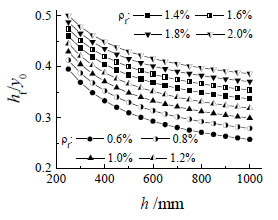
Take h=300 mm and ρf =0.6-1.6%, and suppose y0=0.5h, we can get hf=(0.18-0.22)h. Therefore, all test reinforced SFRFLC superposed beams satisfied the requirement of h1≥hf.
4. ANALYSES OF TEST RESULTS
4.1. Effect of the Sectional Depth of SFRFLC
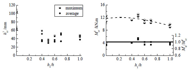
As shown in Fig. (9), the test initial crack height (hcrt) of reinforced SFRFLC superposed beam was shorter obviously than that of reinforced concrete beam, and almost equal to that of reinforced SFRFLC beam. This is because of the restraining of steel fibers to the growth of cracks developed with the increase of sectional depth of SFRFLC. In this study, because the optimal sectional depth of SFRFLC was about half of the sectional depth of beam, resulted in the maximum elastic resistance moment (W0 ) to tensile edge of section of beam, the cracking resistant-moment of reinforced SFRFLC superposed beam with h1/h=0.5 reached the highest.
However, due to the lower modulus of elasticity of SFRFLC, other reinforced SFRFLC superposed beams had the cracking resistant-capacity between reinforced concrete beam and reinforced SFRFLC beam. The reinforced SFRFLC beam had the lowest capacity resisting cracking, as the tensile strain arrived early with larger deflection of beam.
The comparison of test and calculated results of beam with different h1/h is also drawn in Fig. (9) as ratio of Mcrt/Mcrc (here and the same below, Mcrt is the test value of Mcr or Mfcr, Mcrc is the calculated value of Mcr or Mfcr). The ratio varied from 0.908 to 1.117, which shows the good fitness of above formulas. To ensure the sectional cracking resistance no less than reinforced concrete beam, the sectional depth of SFRFLC was better between hf calculated by formula (12) and 0.7h.
4.2. Effect of the Volume Fraction of Steel Fiber
As admixing steel fibers directly improves the tensile strength of SFRFLC, the sectional cracking resistant-moment of reinforced SFRFLC superposed beam is increased correspondingly. Meanwhile, the test initial crack height decreased with the increase of volume fraction of steel fiber, as listed in Fig. (10). The relationship is clear with formulas (3) and (12). As mentioned above, based on the mechanical tests by using the same materials, the enhancement coefficient αt=0.31 in formula (12). From the study of test beams with different volume fraction of steel fiber, the slope and intercept of fitted liner showed in Fig. (10) is 1.72 and 10.43, take λf =ρf×32/0.6, it can be obtained αt=0.309. Therefore, the improvement of steel fibers to the cracking resitance of reinforced SFRFLC superposed beam is identical to the tensile strength of SFRFLC.
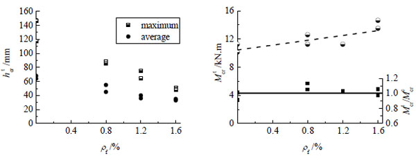
The comparison of test and calculated results of beam with different ρf is also drawn in Fig. (10) as ratio of Mcrt/Mcrc. The ratio varied from 0.912 to 1.132, which shows the good fitness of above formulas.
4.3. Effect of the Longitudinal Tensile Reinforcement Ratio
As shown in Fig. (11), no regularity was the test initial crack height, however the cracking resistant-moment increased with longitudinal tensile reinforcement ratio. This is identical to the reinforced concrete beam [18]. The reasonable increase of longitudinal tensile reinforcement ratio improves the valid development of tensile plasticity to be a larger deformation, which benefits to the tensile-stress adjustment of SFRFLC in tensile zone, and produces a larger sectional plasticity coefficient (γ) of elastic resistance moment. However, when ρ>2%, the cracking resistant-moment did not increse.
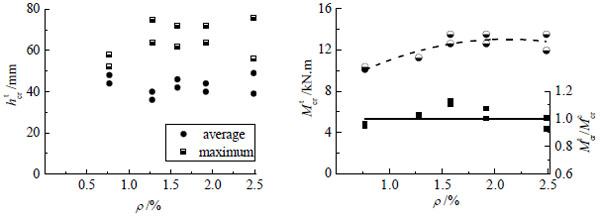
The comparison of test and calculated results of beam with different ρ is also drawn in Fig. (11) as ratio of Mcrt/Mcrc. The ratio varied from 0.928 to 1.132, which shows the good fitness of above formulas.
4.4. Effect of the Compressive Strength of Ordinary Concrete
With the increase of compressive strength of ordinary concrete in compression zone, as Fig. (12), the test initial crack height decreased in some extent, however the cracking resistant-moment did not change obviously. The comparison of test and calculated results of beam with different fc is also drawn in Fig. (12) as ratio of Mcrt/Mcrc. The ratio varied from 1.006 to 1.128, which shows the good fitness of above formulas.
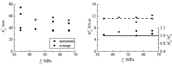
Finally, by using formulas (3)-(8), the calculated Mcrc of reinforced SFRFLC superposed beam can be obtained. The average of all ratios Mcrt/Mcrc is 1.029, the mean square error is 0.086.
CONCLUSION
To ensure the cracking resistance and produce self-lightweight of reinforced SFRFLC superposed beam, the sectional depth of SFRFLC should be taken in a reasonable range. Based on the study, the range was better between hf determined by formula (11) and 0.7h.
Steel fibers restrained the formation and growth of cracks appearing on the tensile zone of superposed beams. The initial crack height was shortened, and the cracking-resistance was improved. This was the main factor affecting cracking resistance and serviceability of reinforced SFRFLC superposed beam.
The reasonable increase of longitudinal tensile reinforcement ratio was beneficial to the cracking resistance of reinforced SFRFLC superposed beam, the effect was identical to reinforced concrete beam. The change of compressive strength of ordinary concrete in compression zone had little influence on the cracking resistance of tested beams.
For design of reinforced SFRFLC superposed beams, calculation formulas of the cross-sectional cracking resistant-moment and the reasonable sectional depth of SFRFLC in tensile zone were proposed. The fitness was evaluated with test data. However, considering the lightweight aggregate used in this paper is expanded shale, researchers may need to consider modification when used for other types of lightweight aggregate such as pumice, expanded clay, polystyrene, oil palm shell etc. since the properties of the resulting concrete may vary significantly. As an important content of structural design, the shear resistance of reinforced SFRFLC superposed beams should be further studied.
CONFLICT OF INTEREST
The authors confirm that this article content has no conflict of interest.
ACKNOWLEDGEMENTS
This work was financially supported by the Scientific and Technical Innovation Team of Eco-building Materials and Structural Engineering in the University of Henan Province, China (13IRTSHN002), the Collaborative Innovation Center of New Building Technology for Cities and Towns, Henan Province, China (Jiaokeji [2013] 638), and the NCWU Innovation Funds for Doctoral Candidate (201515601).


