All published articles of this journal are available on ScienceDirect.
The Collapse Mechanism and Anchored Effect of Bolt-supported Tunnel in Soft Ground
Abstract
The instability even collapse of tunnel would occur during the construction in soft ground. A collapse of expressway tunnel which suddenly encountered soft ground took place just after completing the anchor bolts was investigated as the study background. Based on the plastic and damage constitutive laws, the numerical method of finite element was funded for analyzing the failure mechanism of anchored rock mass and support effects of bolts. Some results were concluded as following by comparing the numerical calculations and field investigations, which would be adopted in further similar engineering. The tunnel collapse is a progressive process with the damage evolution and stress redistributions. The failure zone concentrated near the tunnel crown which can be considered to be the main load on the tunnel structure. According to the length of bolts increases or the spacing distance of bolts decreases, the loosening zones, damage zones, and failure zones will simultaneously become less and less. Nevertheless, those effects become less obvious when the length increases more than 5m or the spacing decreases less than 1m in practice.
INTRODUCTION
The soft ground e.g. faults and fracture zones which are formed by geological deposition or ground moving commonly exists in all types of rock masses. According to the fast development of expressways in China, more and more high classed tunnels would have to be built in soft ground in spite of more adventure and cost [1-3]. Due to its low strength and concealment, soft ground would bring collapses during tunnel construction without timely and reasonable support [4].
Since the bolt was widely used as a stabilization method in tunnel preventing failure of surrounding rock mass, it has attracted more and more attention of researchers about its effects [5]. Since the method of numerical simulation has some advantages, i.e., less cost, more result information and less time, the numerical analysis for the effects of anchored tunnel have greatly been carried out, which mainly included the continuum-based methods. For example Maghous et al. [6] introduced an anisotropic constitutive law by using a 3D finite element computer codes to deal with the processes of excavation, installation of bolts and lining placement. Li et al. [7] used the finite difference software FLAC to investigate the effects of length, density, and rigidity of bolts of tunnel within soft rock. To some extent, the results of numerical simulation are not too accurate to meet the requirements of engineering applications due to the parameters and constituting law of rock mass [7]. On the other hand, the mechanism study is acceptable to meet the requirement of engineering by studying some mechanical rules of structure. For example Dhawan et al. [8] analyzed the effects of weak zones in the ground and creation of multiple cavities in the inhomogeneous rock mass using finite element method.
Despite fully grouted bolts are nowadays widely used for tunnel support, bolting design of tunnel in China is still based on empirical or semi-empirical considerations in many cases [9]. In this paper, firstly, a case history of tunnel collapse is investigated. And then, a numerical simulation is carried out by finite element method for comparison with the field results to understand the failure mechanism of rock mass surrounding tunnel. Finally, other numerical simulations are further done for analyzing the anchored effect of bolt-supported tunnel.
ENGINEERING BACKGROUND
The expressway from Wuning to Yanji is located in Jiangxi province of China, which is one part of the national road from Daqing to Guangzhou and 285.809 km in all. The road line meets some serious geological disasters e.g. landslide during investigation stage. Therefore, tunnel is considered to be a better plan to deal with them. As a result, there are 24 tunnels and 60.8435 km built in all.
A collapse took place in the middle section of Nashaling tunnel with a length of 1785 m, which is selected as the study background. The dimension of tunnel is shown in Fig. (1). The overburden depth is 32.5 m, the crossing section is about 150 m2, the span is 16 m and the height is 9 m. According to the initial field investigation, the ground near tunnel mainly is made up of metamorphic rocks which is referred as Grade III according to Chinese design codes of road tunnel [10], which is a relatively good classification and can be excavated by the method of full section tunneling. Since the overburden depth of tunnel is relatively low, the in-situ stress along vertical direction meets the rule of gravity loading, and the horizontal direction is evaluated to be 0.47 time of vertical one according to the equilibrium theory. The grouted anchor bolts were designed as what is shown in Fig. (1), which is a diameter of 25 mm, a length of 5 m, and a tangential spacing distance of 1.5 m.
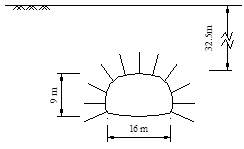
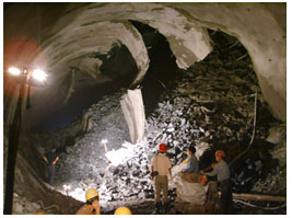
Unfortunately, a fracture zone was encountered when the tunnel went to the middle section with a buried depth of 32.5 m as shown in Fig. (1), which was not foreseen because of front better rock mass. Due to the sudden variation of ground softening and inadequate support strength, the collapse with large volume took place during shooting concrete as shown in Fig. (2). It will not be considered because of not giving birth to strength and we will pay more attention to the effects of anchor bolts in the further numerical simulations.
According to field investigations, the rock mass of the soft ground is mainly made up of sandy slate, which is badly weathered and fractured with just a little underground water. The physical and mechanical parameters of the rock mass are presented in Table 1 by the field investigations and laboratory tests including uniaxial compression test and conventional triaxial test. They will be adopted as the parameters of rock mass in numerical simulations.
| Bulk weight | Elastic modulus | Poisson’s ratio | Cohesion | Friction angle | Uniaxial compression |
|---|---|---|---|---|---|
| kN/m3 | GPa | MPa | ° | MPa | |
| 21 | 3.1 | 0.32 | 0.5 | 35 | 10 |
NUMERICAL SIMULATION METHOD
Constitution Model
The numerical simulations are performed using the finite element (FE) software ABAQUS. A plastic damage constitution model is adopted with a criterion of Drucker-Prager yield [11], which was verified to be reasonable for study the problems of strain softening and progressive failure of soft rock mass [12] and recited as following:
If the stress estimation was beyond yield criterion, it appeared that the material damage initiated with plastic strain. According to strain equivalent law proposed by Lemaitre [13], the Cauchy stress σ ij will be replaced by effective stress
 , while material stiffness is degraded progressively according to the specified damage evolution response. The relationships can be defined as following form:
 |
(1) |
where,
 is the renewed elastic stiffness, D is the value of damage variable, which generally ranges from 0 to 1. Considering the residual strength of the material, the maximum value of damage variable is set as 0.8 according to the uniaxial compression test of similar rock materials [12].
Thus, the initialization and evolution of damage variable are critical specifications of the model. The initiative damage is determined by the equivalent plastic strain ε0pl, which is obtained by Equations (3). The damage variable will evolve with a linear form defined by equivalent plastic strain, which is given as:
 |
(2) |
where, ε fpl is equivalent plastic strain when the damage variable reaches the maximum. In the failure process of the model material, there are linear elastic, plastic hardening, and plastic softening phases. The relations between strain values at different phases are proposed as follows [14]:
 |
(3) |
where, the uniaxial compression strength σc can be obtained from Table 1 and the maximum elastic strain εe can be automatically passed by ABAQUS during calculation iteration.
FE Models and Schemes
A kind of 8-nodes linear brick element is introduced for rock mass surrounding tunnel, whose parameters are adopted according to the Table 1. An elastic structure element Truss3D adhere to ABAQUS is selected for simulating the anchor bolts with the elastic modulus of 300 GPa, Poisson’s ratio of 0.3 and geometric parameters presented in Fig. (1).
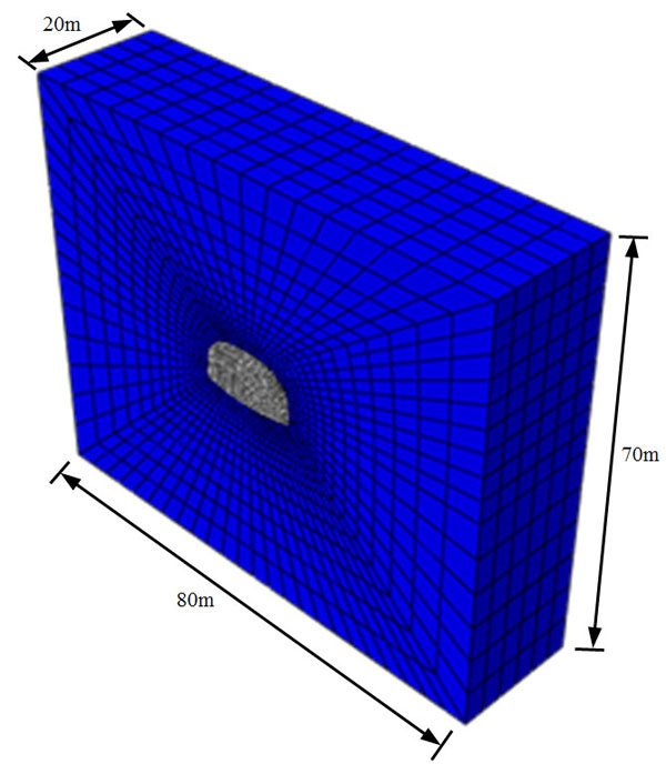
According to the size of tunnel, the study dimension simulated by numerical method is 80m×75m×20m. The model of finite element is constructed for studying the failure mechanism of tunnel collapse by mapping mesh as shown in Fig. (3), which includes 8160 elements and 9972 nodes. The lateral boundaries are only constrained along normal directions and the bottom one is restricted by three directions.
For studying the support effects of anchor bolts of tunnel, some other numerical simulations are carried out by changing the geometric parameters. The schemes are presented in Table 2.
| Item | Study aims | The Parameters of bolts /m | |
|---|---|---|---|
| Length L /m | The spacing B /m | ||
| 1 | Comparison with field | 0.5 | 2.5 |
| 2 | The effects of length | 0, 3, 5, 8 | 2.5 |
| 3 | The effects of spacing | 5 | 0.5, 1, 2.5, ∞ |
COLLAPSE MECHANISM
The Progressive Process of Failure
The process of tunnel collapse is reproduced by the numerical simulation as shown in Fig. (4), which is completed by 1000 sub steps in all after excavation. The red zones mean the failure zone with the complete damage of rock mass (D=0.8), the blue zones mean no damage of the rock mass (D=0), and the other zones indicate the partial damage of rock mass (0.8>D>0). At initial stage as shown in Fig. (4a), the failure zones distribute with some gaps at the positions of anchor bolts and the zones will develop as the calculation sub step increases as shown in Fig. (4b). Finally as shown in Fig. (4c), the terminal failure zones are almost continuous concentrated inner about 4m to tunnel surface which will bring on the tunnel collapse, while the damage zones are analogously distributed but greatly more than it.
(a)sub step=100 (b)sub step =500 (c)sub step =1000
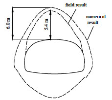
The final failure zone of rock mass surrounding tunnel is compared between numerical simulation and field investigation, which is shown in Fig. (5). They are very similar to each other, especially for the part on the top of tunnel crown, which is always made up of the loosening load to tunnel structure. The comparison shows that the method of numerical simulation is reasonable and believable.

The Stress Adjustment After Tunneling
Generally speaking, tunnel excavation will break the initial stress balance of ground and cause stress redistribution [15]. According to the results of ground stress redistribution, the inner surrounding rock mass of tunnel can be divided into: stress loosening zone (Δσθ < 0, Δσr < 0), stress bearing zone (Δσθ > 0, Δσr < 0) and in-situ stress zone (Δσθ → 0, Δσr → 0), as presented in Fig. (6).
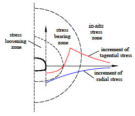
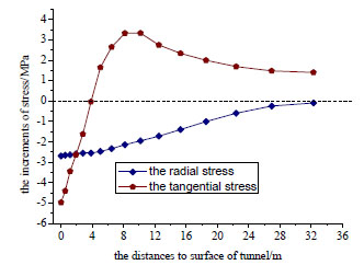
The tangential stress increment Δσθ and radial one Δσr of tunnel hance are presented in Fig. (7). Their distributions of variation with the depth greatly agree with the rules of Huang’s results as shown in Fig. (6) [15]. The stress loosening zone derived from ground is about 4 m according to the rule of stress increment Δσθ < 0.
ANCHORED EFFECTS
The Effects of Bolts Length
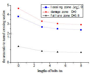
The damage zone, failure zone and loosening zone with the different length of bolts are compared as shown in Fig. (8). It is not difficult to find out that the 3 kinds of zones have the analogous rules: the more is the length, the less is the zone area. However, the zones variation with length of bolt become less obvious when the length is more than 5 m. Therefore, the length of more than 5 m is usually not expected, which also meets the requirements of Chinese design codes of road tunnel [10].
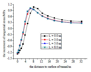
The tangential stress increments Δσθ of tunnel hance with the different length of bolts are presented in Fig. (9). Since the rock mass are strengthened by anchor bolts, the peak stress increment move inner tunnel, which means there will be less loosening zone with more length of bolts. Since the results of length of 5 m are almost same as the case of 8 m, the support effect of bolt is very little when the length is over 5m. Consequently, the length of bolts is not expected to be over 5 m in practice for not wasting money.
The Effects of Bolts Spacing
The damage zone, failure zone and loosening zone with different spacing of bolts are presented in Table 3. The 3 kinds of zone also become less with less spacing of bolts. In fact, the results of spacing of 1m are almost the same as the one of 0.5 m. It indicates the support effect of bolt is very little when the spacing of bolts is less than 1m, which is unnecessary and uneconomical in practice. It agrees with the Zou and Wang’s results from model tests in laboratory, which suggested that the ratio between the length and spacing of bolts should be less than 5 [16].
| Spacing between bolts /m | The area ratios to tunnel crossing section | ||
|---|---|---|---|
| Loosening zone | Damage zone | Failure zone | |
| ∞ | 3.812 | 4.674 | 0.633 |
| 2.5 | 2.496 | 3.06 | 0.414 |
| 1 | 1.654 | 2.028 | 0.274 |
| 0.5 | 1.503 | 1.842 | 0.249 |
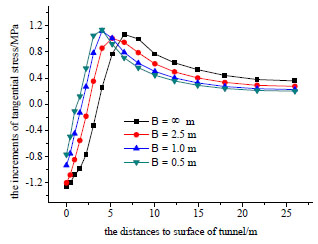
The tangential stress increments Δσθ of tunnel hance with the different spacing of bolts are presented in Fig. (10). With the decrease in spacing of bolts, the stress increments move inner tunnel because the strength of rock mass is enhanced by bolts. By comparison, the effects of bolts spacing are more notable than the effects of bolt length under other same conditions.
CONCLUSION
By introducing plastic damage constitutive laws, a numerical simulation is conducted by finite element method, which is validated by comparing with the results of field investigations. On this basis, the mechanism of tunnel collapse and the support effects of anchor bolts are studied by some further numerical simulations.
The tunnel collapse can be described to be a progressive process of failure of rock mass surrounding tunnel, which would be reasonably denoted by the maximum value of damage variable. The failure zone concentrated mainly near the tunnel crown which can be considered to be the loose load on the tunnel structure. Based on the redistribution of tangential stress increment, the ground surrounding tunnel can be divided into stress loosening zone, bearing arch zone, and in-situ stress zone.
As the length of bolts increases or spacing of bolts decreases, the loosening zone, damage zone, and failure zone will simultaneously become less and less. Nevertheless, it is noteworthy that the support effects of anchor bolts will be less and less obvious when the length increases more than 5m or spacing decreases less than 1m, which should be paid great attention in designing parameters of anchor bolts especially for tunnels in soft ground.
CONFLICT OF INTEREST
The authors confirm that this article content has no conflict of interest.
ACKNOWLEDGEMENTS
This work is supported by the National Natural Science Foundation of China (No. 51308574), the project of Chongqing science and technology commission (No. cstc2016shmszx30009, No. cstc2013jcyjA30007), the Fund of State Key Laboratory Breeding Base of Mountain Bridge and Tunnel Engineering (No. CQSLBF-Y13-4), the post doctor Science Foundation of China (No. 2014M562286), and the natural science project of Chongqing education commission (No. KJ130404, No. KJ130408).


