All published articles of this journal are available on ScienceDirect.
Simulation Study of the Load-settlement Behavior of a Single Pile Using the Osterberg-cell Test Based on the Load Transfer Theory
Abstract
In this paper, a theoretical relationship between the load and settlement of a single pile in an Osterberg-Cell test was developed, considering the joint action of piles and soil and a detailed deformation analysis was conducted based on the load transfer theory of piles. The shear test and the compression test were used to determine the load transfer parameters for soil layers around a pile at various depths as well as the parameters for pile-tip soils. Based on this method, a simulation analysis program was applied to determine the location of the balance point in the Osterberg-Cell test to provide a reference for the test design. The analytical methods presented in this paper could be considered practical because the results from the simulation test and on-site measurement indicate that the theoretically predicted result is consistent with the measurements. A reasonable selection of the location of the hydraulic jack-like device (O-cell) could maximize the bearing capacity of testing piles to obtain a more accurate ultimate bearing capacity. This study provides a reference for the design of the Osterberg-Cell test as well as pile foundations.
1. INTRODUCTION
The Osterberg-Cell test (O-cell or bi-directional loading test) is commonly used to predict the load-settlement behavior of large-diameter drilled shafts. In 1984, Osterberg used this method in a practical application and made it widely accessible [1]. The O-cell works in two directions - upward against the side shear and downward against the end bearing, thus separating the upper and lower resistance components [2]. The Osterberg-Cell test provides high capacities at an affordable cost, which has made it a widely used alternative method for testing drilled shafts. Although the Osterberg-Cell test still requires theoretical improvements, its technological and economic advantages enable it to be widely used in practical engineering in China and many other countries [3-6]. Previous studies on the Osterberg-Cell test have primarily focused on its engineering applications [7-9] and issues during pile tests [10-12], also an equivalent pile load-head settlement curve to predict pile capacity [13-17]. Y. Choi et al. [18] had conducted a study on the determination of loading capacities for bi-directional pile load tests based on actual load test results. A modified analytical solution is presented to analyze the axial pile response of bi- direction O-cell loading by F.S. Niazi and P.W. Mayne [19].
In this paper, a theoretical relationship between the load and settlement of a single pile in an Osterberg-Cell test was developed, considering the joint action of piles and soil and a detailed deformation analysis was conducted based on the load transfer theory of piles. Additionally, this paper provides detailed deformation analysis procedures. The shear and the compression tests were used to the determine load transfer parameters for different soil layers around a pile at various depths as well as the parameters for soil at the tip of a pile. Based on this method, simulations can be conducted to determine the locations of the hydraulic jack-like device (O-cell) in the Osterberg-Cell test and determine a reasonable location of the O-cell. A relatively accurate ultimate bearing capacity can be obtained to provide a reference for the design of the Osterberg-Cell test and the bearing capacity of the pile foundation.
2. THEORETICAL ANALYSIS OF A SINGLE PILE DEFORMATION USING THE OSTERBERG-CELL TEST
2.1. Hyperbolic Model of the Load Transfer Function
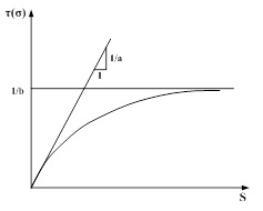
The hyperbolic model, which uses in the load transfer function of the pile shaft, has been proposed by H.B. Seed and L.C. Reese [20], the relationship between the skin friction along the pile shaft and the displacement as well as the relationship between the end-bearing resistance and tip settlement was expressed by the hyperbolic function:
On the lateral side of the pile:
 |
(1) |
At the tip of the pile:
 |
(2) |
Where, τ is the skin friction along the pile, σb is the end-bearing resistance, S is the displacement of the pile, Sb is the tip settlement, af and bf are the load transfer parameters of soil layers around the pile, and ab and bb are the load transfer parameters of the pile-tip soils.
Fig. (1) presents the model that uses the hyperbolic load transfer, where 1/a and 1/b are the reciprocals of the load transfer parameters.
2.2. Iterative Model of the Load-settlement Relationship of the Pile Shaft
A finite element dz from the pile shaft and Eq.(3) can be obtained in accordance with static equilibrium conditions:
 |
(3) |
Where, P(z) is the axial force of the pile shaft, up is the perimeter of the section of the pile, and τ(z) is the skin friction along the pile shaft.
The elastic compression modulus produced by the micro-module is expressed as follows:
 |
(4) |
Where, S is the displacement of the pile shaft, E is the elastic module of the pile, and A is the cross-sectional area of the pile shaft.
Applying a differential transformation to Eq. (3) yields
 |
(5) |
Substituting Eq. (3) and Eq. (4) into Eq. (5) yields
 |
(6) |
Substituting the hyperbolic modular form of Eq. (1) of the load transfer function into Eq. (6) and setting α = up EA yields
 |
(7) |
Expressing Eq. (7) in incremental form yields
 |
(8) |
Eq. (8) is the iterative model that was used to solve the load-settlement relationships of the pile shaft [21].
3. LABORATORY TEST METHOD USED TO DETERMINE THE LOAD TRANSFER PARAMETERS
The shear test and the compression test can be used to determine the load transfer parameters of the soil, which can then be used to analyze the load-settlement relationships of the piles, if the pile diameter is too large to conduct complete on-site load test [21-23].
3.1. Laboratory Shear Test
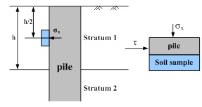
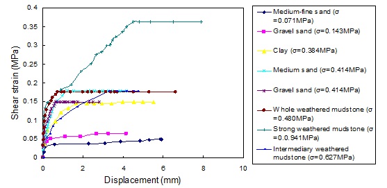
In this paper, a laboratory shear test was conducted to determine the load transfer parameters of lateral soils of a pile that are more representative of actual conditions between the piles and soil. The theoretical background of the laboratory shear test is discussed by B. Qi et al. [24]. The gravity stress and lateral soil pressures can be calculated at various depths according to the detailed depths of all soil samples in the natural soil layer. Fig. (2) presents schematic profile of the load transformation. These parameters can be used as the normal stress in the shear test to determine the relationship between the shear stress τ and shear displacement S if equal strain shear is achieved. A hyperbolic curve was fit to the test curve, as shown in Eq. (1), which yields the load transfer parameters af and bf on the contact surface between the pile and soil.
3.2. Laboratory Compression Test
The compression test can be used to determine the compression modulus ES on the tip of the soil to calculate the modulus of deformation EO. In 1979, M.F. Randolph and C.P. Wroth [25] suggested that the equation for the displacement soil at the tip of the pile can be solved by using the Boussinesq formula, yielding
 |
(9) |
Where, ω was set as 0.79 for the rigid block. The load is smaller; the curve of Pb and Sb is approximately linear. From Eq. (2), the slope can be expressed as 1/ab, yielding
 |
(10) |
The term 1/bb in Eq. (2) indicates that the maximum force of the reaction can be obtained by performing laboratory triaxial test. The sample soil on the tip of the pile is collected and placed in a triaxial apparatus. Lateral confining pressure is applied, and axial compression is exerted until the sample is destroyed. As a result, the compressive strength of the sample is determined, and the maximum force of reaction on the tip of the pile is determined by considering the size effect and theory of the equivalent sample cross section.
4. METHODS OF CALCULATING THE LOAD-SETTLEMENT RELATIONSHIPS OF THE PILE SHAFT
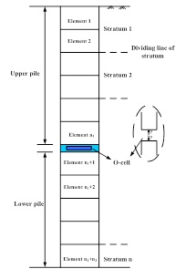
In this paper, the body of the pile in the Osterberg-Cell test is divided into upper and lower parts based on the location of the O-cell. The body is also subdivided into several units (the interface of the natural soil layer and the location of the O-cell must be selected as the interface of the subsection), as shown in Fig. (3).
The calculation procedure for the upper section of the pile is described as follows:
(1) First, the upper section of the pile is divided into n1 subsections.
(2) Given the displacement on the top of the pile as S 0, the skin friction along the pile of the first subsection can be calculated using Eq. (1), yielding
 |
(11) |
(3) The change in the axial force of the pile shaft (ΔP1) and the axial force of the pile shaft (P1) on the top surface of the first subsection are calculated according to τ, yielding
 |
(12) |
| P1 = ΔP1 | (13) |
(4) The average axial force of the first subsection (
 ) is calculated according to P1, yielding
 |
(14) |
(5) The elastic compression of the first subsection (ΔS1) and the displacement of the pile shaft on the underside of the first subsection (S1) are calculated according to
 , yielding
 |
(15) |
 |
(16) |
(6) In the above calculations, the skin friction along the pile of the first subsection should be equally distributed along the pile; however, the displacement of the pile shaft varies with depth. As a result, the lateral friction distributed along the pile shaft also varies. Therefore, satisfactory results can only be obtained by substituting P1 , S1 , and ΔS1 into Eq. (12) and performing iterative calculations on the first subsection, yielding
 |
(17) |
 |
(18) |
 |
(19) |
 |
(20) |
 |
(21) |
(7) In general, the values of ΔP'1 , P'1 , ΔS'1 , and S'1 from the calculation at this time are not equal to the values of ΔP1 , P1 , ΔS1 , and S1 and obtained above. So, iterative calculations are required. At each iteration, the values of P'1 , ΔS'1 , and S'1 that were obtained from the calculation are used for the values of P1 , ΔS1 , and S1 and substituted into Eq. (17) to calculate new values for P'1 , ΔS'1 , and S'1 until the results are within the specified accuracy. In general, the results are acceptable if the relative error of the load (or displacement) increment calculated at both times is less than 5%. The values of P1 and S1 calculated from Eq. (18) and Eq. (21) represent the axial force and displacement, respectively, of the pile shaft on the underside of the first subsection and on the top surface of the second subsection.
(8) P1 and S1 are used as the axial force and displacement respectively, of the pile shaft on the top surface of the second subsection and substituted into Eq. (11) through Eq. (21). P2 and S2 can be obtained after the same iterative calculations are performed on the second subsection, and so on. The calculations can be performed until the bottom of the upper section of the pile and Pn1 and Sn1 and are obtained. During the calculations, various values of and are applied to different soil layers (such as af1, bf1, af2, bf2).
The calculation procedure for the lower section of the pile is described as follows:
(9) First, the lower section of the pile is divided into n2 subsections.
(10) Given the settlement on the tip of pile as Sb. The reaction on the tip of the pile (Rb) is calculated according to Eq. (2) as follows:
 |
(22) |
(11) The skin friction along the pile on the n1 + n2 subsection is calculated according to Eq. (1) as follows:
 |
(23) |
(12) The change in the axial force of the pile shaft on the top surface of the n1 + n2 subsection (Δ Pn1 + n2) and the axial force of the pile shaft on the top surface of the n1 + n2 subsection (Pn1 + n2) are calculated according to τ as
 |
(24) |
 |
(25) |
(13) The average axial force on the n1 + n2 subsection (
 ) is calculated according to Pn1 + n2 as follows:
 |
(26) |
(14) The values of ΔSn1 + n2 , the elastic compression on the n1 + n2 subsection, and Sn1 + n2 , the settlement of the pile on the top surface of the n1 + n2 subsection, are calculated according to
 as follows:
 |
(27) |
 |
(28) |
(15) The iterative calculation steps for the lower part of the pile are the same as steps (7) and (8). The calculations can be performed until the top of the lower section of the pile and Pn1+1 and Sn1+1 are obtained.
Different values of S 0 and Sb can be used to calculate various bottom loads (P 0) and the bottom displacement (Sn1) of the upper section of the pile as well as various upper loads (P 0) and the upper displacement (Sn1 +1) on the top of the pile.
5. DETERMINATION OF THE LOCATION OF THE BALANCE POINT IN THE OSTERBERG-CELL TEST
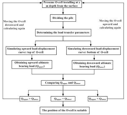
For the Osterberg-Cell test, the ultimate bearing capacity can only be accurately measured if the O-cell is located at the balance point. Otherwise, one section of the pile reaches the ultimate bearing capacity and the other section fails. As a result, the calculated ultimate bearing capacity will be less than the actual capacity, indicating that the result tends to be conservative [10, 11]. The actual ultimate bearing capacity is not measured, and unnecessary loads are produced. An empirical correlation is frequently used to determine the location of the O-cell. However, this method has some limitations. As a result, a simulation analysis was conducted on the relationship between the load and settlement of the pile shaft on both the upper and lower sections of the piles based on the load transfer mechanism to determine the location of the load box in the Osterberg-Cell test. It presents the calculation procedures that were used to determine the location of the O-cell in Fig. (4).
6. FIELD OBSERVATION CALCULATIONS AND DISCUSSION
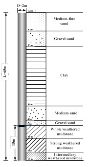
By means of Osterberg-Cell test, data and laboratory test information were obtained from test piles in the Longhua Temple-Songhua River Grand Bridge project in Jilin Province, China. A computational analysis of the load-settlement relationships of the Osterberg-Cell test was conducted by using the numerical simulation method described in this paper. The location of the O-cell was also discussed. The diameter of the test pile was 2 m, the length of the pile was 65 m, the elastic modulus of the pile shaft was 31500 MPa, and the O-cell was installed at a depth of 50 m. Fig. (5) presents a schematic profile of the soil conditions and test pile. The main geotechnical parameters of the soils around the pile are shown in Table 1.
According to the depths of the soil layers, the normal stress required to be exerted to all soil samples during the shear test was calculated and is provided in Table 2.
| Medium-fine sand |
Gravel sand |
Clay | Medium sand |
Gravel sand |
Whole weathered mudstone |
Strong weathered mudstone |
Intermediary weathered mudstone |
|
|---|---|---|---|---|---|---|---|---|
| Density (g/cm3) |
2.07 | 2.14 | 1.91 | 1.95 | 2.14 | 2.10 | 1.90 | 2.10 |
| Water content (%) |
20.45 | 13.20 | 29.38 | 18.91 | 13.20 | _ | _ | _ |
| Liquid limit (%) |
_ | _ | 37.22 | _ | _ | _ | _ | _ |
| Cohesion (kPa) |
0 | 0 | 10 | 0 | 0 | 35 | 70 | 100 |
| Friction angle (°) |
19.9 | 25.5 | 11.0 | 21.0 | 25.5 | 16.5 | 18.0 | 20.0 |
| Elastic modulus (MPa) |
_ | _ | _ | _ | _ | 25.99 | 10.31 | 14.62 |
| Poisson ratio | _ | _ | _ | _ | _ | 0.345 | 0.335 | 0.330 |
| Soil sample | Medium-fine sand |
Gravel sand |
Clay | Medium sand |
Gravel sand |
Whole weathered mudstone |
Strong weathered mudstone |
Intermediary weathered mudstone |
|---|---|---|---|---|---|---|---|---|
| Normal stress (MPa) |
0.071 | 0.143 | 0.384 | 0.414 | 0.414 | 0.480 | 0.941 | 0.627 |
The laboratory shear test can be used to obtain results for the shear stress between the contact layers of the soil layers and piles (represented by τ) and the horizontal shear displacement (represented by S), as shown in Fig. (6).
The laboratory compression test conducted on the soil at the tip of the pile can be used to obtain the compression modulus of the soil at the tip of the pile (Es=307 MPa) by applying Eq. (10) and the laboratory triaxial test as follows:
1/ab=500 MN/m3, and 1/bb=250 MPa.
The laboratory test can be conducted to obtain the load transfer parameters of the soil on the lateral side of the pile and at the tip of the soil, as shown in Table 3.
| Stratum | Medium-fine sand | Gravel sand | Clay | Medium sand | Gravel sand | Whole weathered mudstone | Strong weathered mudstone | Intermediary weathered mudstone |
Bottom soil |
|---|---|---|---|---|---|---|---|---|---|
| a | 0.047 | 0.031 | 0.022 | 0.0048 | 0.0036 | 0.0003 | 0.0002 | 0.003 | 0.002 |
| b | 20.576 | 15.561 | 6.711 | 5.622 | 6.732 | 5.676 | 2.755 | 5.628 | 0.004 |
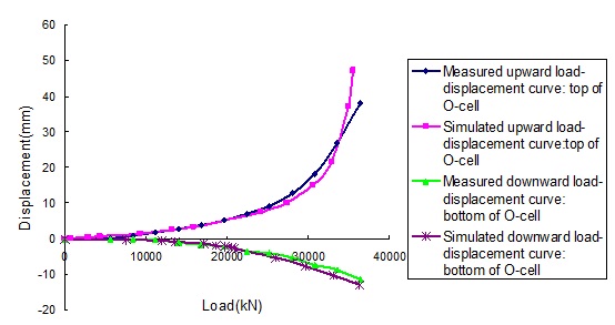
The above calculation steps can be used to obtain the load-displacement curve of the pile shaft in the Osterberg-Cell test, as shown in Table 4. Fig. (7) presents the load-displacement curves from the Osterberg-Cell test and simulation on the pile. In this figure, downward displacement is represented by negative values.
| Load (kN) |
Measured upward displacement (mm) |
Measured downward displacement (mm) |
Load (kN) |
Simulated upward displacement (mm) |
Load (kN) |
Simulated downward displacement (mm) |
|---|---|---|---|---|---|---|
| 5600 | 0.25 | 0.07 | 690.55 | 0.067 | 7617.41 | 0.37 |
| 8400 | 0.86 | 0.15 | 2820.99 | 0.31 | 11916.80 | 0.74 |
| 11200 | 1.75 | 0.43 | 4385.37 | 0.53 | 13570.29 | 0.93 |
| 14000 | 2.74 | 1.18 | 9322.51 | 1.46 | 17081.63 | 1.48 |
| 16800 | 3.86 | 1.71 | 13233.81 | 2.47 | 18655.13 | 1.86 |
| 19600 | 5.11 | 2.31 | 15833.92 | 3.32 | 19743.01 | 2.18 |
| 22400 | 6.82 | 3.63 | 24122.76 | 7.33 | 20598.42 | 2.49 |
| 25200 | 8.95 | 3.96 | 27401.81 | 10.13 | 20972.04 | 2.64 |
| 28000 | 12.57 | 5.32 | 30622.64 | 14.91 | 25961.94 | 5.31 |
| 30800 | 18.2 | 7.44 | 32819.64 | 21.44 | 29686.94 | 7.84 |
| 33600 | 26.88 | 8.86 | 34907.26 | 36.94 | 33097.32 | 10.34 |
| 36400 | 38.03 | 11.44 | 35512.79 | 47.08 | 36361.17 | 12.83 |
After-test residue checking method is used to check the reliability of the simulated values. The principle of this method is as follows [26].
 |
(29) |
Where, ε(i) is the difference in values between the measured and simulated displacements, x(i) is the measured displacement,
 is the simulated displacement, n is the number of data.
The mean value of ε(i) can be obtained by Eq.(30).
 |
(30) |
The variance ε(i) of can be obtained by Eq.(31).
 |
(31) |
The mean value of measured displacements can be obtained by Eq.(32).
 |
(32) |
The variance of measured displacements can be obtained by Eq.(33).
 |
(33) |
C is the ratio of S1 and S2 , P is the small error probability, and they are the test indexes. The accuracy level which is divided by these two indexes is shown in Table 5.
 |
(34) |
 |
(35) |
| Accuracy level | P | C |
|---|---|---|
| GOOD | >0.95 | <0.35 |
| QUALIFIED | >0.8 | <0.5 |
| JUST MARK | >0.7 | <0.45 |
| UNQUALIFED | ≤0.7 | ≥0.65 |
In order to check the simulated values, the measured displacements and simulated displacements under the same load which are found from Fig. (7) are shown in Table 6. And the difference values between the measured and simulated displacements are also shown in Table 6.
| Load (kN) |
Measured upward displacement (mm) |
Simulated upward displacement (mm) |
ε(i) | Measured downward displacement (mm) |
Simulated downward displacement (mm) |
ε(i) |
|---|---|---|---|---|---|---|
| 5600 | 0.25 | 0.50 | -0.25 | 0.07 | 0.25 | -0.18 |
| 8400 | 0.86 | 1.10 | -0.24 | 0.15 | 0.40 | -0.25 |
| 11200 | 1.75 | 1.75 | 0 | 0.43 | 0.70 | -0.27 |
| 14000 | 2.74 | 2.75 | -0.01 | 1.18 | 1.00 | 0.18 |
| 16800 | 3.86 | 3.86 | 0 | 1.71 | 1.60 | 0.11 |
| 19600 | 5.11 | 5.11 | 0 | 2.31 | 2.20 | 0.11 |
| 22400 | 6.82 | 6.50 | 0.32 | 3.63 | 3.20 | 0.43 |
| 25200 | 8.95 | 7.20 | 1.75 | 3.96 | 4.20 | -0.24 |
| 28000 | 12.57 | 11.00 | 1.57 | 5.32 | 5.30 | 0.02 |
| 30800 | 18.20 | 16.00 | 2.20 | 7.44 | 6.60 | 0.84 |
| 33600 | 26.88 | 26.88 | 0 | 8.86 | 7.60 | 1.26 |
Calculation results of each parameter which are obtained by Eq. (29) to Eq. (35) are shown in Table 7.
 |
 |
 |
 |
C | P |
|---|---|---|---|---|---|
| 0.33 | 5.59 | 0.49 | 41.06 | 0.109 | 1 |
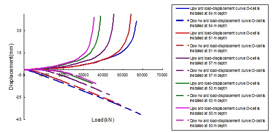
According to Table 6, C=0.109<0.35,P>0.95, so the accuracy level is good, and the results show that the simulated results are in good agreement with the measured results. In Fig. (7), it illustrates that the load-displacement curves obtained through simulation are in good agreement with the results obtained from the Osterberg-Cell test. If the lower section of the pile does not reach its ultimate bearing capacity when the upper section of the pile reaches its ultimate bearing capacity, then the O-cell is not in its correct location (but is partially above it). The calculation steps shown in Fig. (4) can be used to move the O-cell downward to obtain curves that provide the load-displacement curve of the pile shaft for different O-cell locations, as shown in Fig. (8). If the O-cell moves downward, then the length of the pile on the upper section of the O-cell increases, and the skin friction also increases and allows for a higher load bearing capacity in the upper section of the pile. The load bearing capacity of the lower section of the pile is gradually utilized as the O-cell moves downward. If the O-cell is installed at a depth of 64 m from the top of the pile, then the ultimate bearing capacity of the piles (both on the upper and lower sides of the O-cell) can be maximized.
The compressive ultimate bearing capacity of the single pile can be calculated according to Eq. (36).
 |
(36) |
Where, Qu is the vertical compressive ultimate bearing capacity, Quu is the limit value of the pile on the upper side of the O-cell, Qud is the limit value of the pile on the lower side of the O-cell, W is the dead weight of the pile on the upper side of the O-cell, and γ is the correction factor of the lateral resistance of the pile on the upper side of the O-cell (0.8 is used for cohesive soil and silt, and 0.7 is used for sandy soil).
It presents the ultimate bearing capacity of the pile shaft if the O-cell is installed at different depths in Table 8. If the resistance on the tip of the pile is greater than the skin friction or approximately equals to the skin friction, the measured bearing capacity is closer to the ultimate bearing capacity when the O-cell was located on the bottom of pile or near the bottom of the pile.
| Position of O-cell | 50 m | 53m | 57 m | 61 m | 64 m |
| Ultimate bearing capacity of upper pile Qupper (kN) |
34907 | 38172 | 44782 | 53209 | 56947 |
| Ultimate bearing capacity of lower pile Qlower (kN) |
>34907 | >38172 | >44782 | >53209 | 56947 |
| Length of upper pile (m) | 50 | 53 | 57 | 61 | 64 |
| Weight of upper pile (kN) |
3925 | 4160.5 | 4474.5 | 4788.5 | 5024 |
| Correction coefficient γ | 0.8 | 0.8 | 0.8 | 0.8 | 0.8 |
| Ultimate bearing capacity Qu (kN) |
>73634 | >80686 | >95166 | >113734 | 121850 |
CONCLUSION
The study can be summarized as follows:
(1) The load transfer parameters of various soil layers at different depths and the load transfer parameters of soil at the tip of the pile can be determined by the shear test and the compression test. This result can provide parameters that can be used in the numerical simulation method.
(2) According to the after-test residue checking method, C=0.109<0.35,P>0.95, so the accuracy level is good, and the results show that the simulated results are in good agreement with the measured results. Moreover, curves obtained by the Osterberg-Cell test are in good agreement with the curves that demonstrate the load-displacement curve determined by using the numerical simulation method described in this paper. Therefore, this method can be used to analyze the deformation law of the pile shaft in the Osterberg-Cell test measurement and to determine the ultimate bearing capacity of the test pile, which can reduce or replace a partial pile test on-site. Thus, the method described in this study has economic implications.
(3) The simulation analysis procedures proposed in this paper are used to determine the location of the O-cell in the Osterberg-Cell test, and the measured bearing capacity is closer to the ultimate bearing capacity if the O-cell is in the right position. A reference for the design of the Osterberg-Cell test and pile foundation can be provided.
CONFLICT OF INTEREST
The authors confirm that this article content has no conflict of interest.
ACKNOWLEDGEMENTS
This work is financially supported by the National Natural Science Foundation of China (51678275).


