All published articles of this journal are available on ScienceDirect.
Design Device for Suspension Type Disaster-prevention and Rescue, and Maintenance of Tunnel
Abstract
A suspension tunnel rescue device is studied, which includes a guide rail installed on the top of the tunnel, and an operating system platform mounted on the bottom of the wheel. Advantages: firstly, the rescue platform can achieve a barrier-free movement as it is suspended on the guide rail. In the case of fire in the tunnel, the rescue platform can quickly reach the disaster location to avoid personal injury and property loss even if the tunnel is blocked; secondly, the rescue platform and fire extinction platform can be disassembled from each other, to provide a non-blocking working platform for inspection and maintenance in tunnel. In addition, an umbrella type combined nozzle which is composed of the auxiliary nozzle and the main nozzle was designed. The auxiliary nozzles spray water to isolate the fire while the distribution circumference of the subsidiary nozzles is adjustable.
1. INTRODUCTION
Tunnel is a peculiar run-through structure, normally it is used for water or mountain crossings, construction of urban three-dimensional traffic, composing of urban comprehensive pipe gallery and other functions. However, with the increase of the scale of the tunnel project, the major disaster also occurred frequently in the tunnel in the recent years [1, 2]. Laura Moretti offered that safety measures for tunnel account a big part of total budget for the management of tunnel, and is essential [3]. The causes of the tunnel fire incident are complicated. In the survey of vehicle fires in Norwegian road tunnels, Tor-Olav Nævestad concluded that heavy and light vehicles have different influence on tunnel fires and technical failures may also cause tunnel fires. The economic loss caused by the long-term fire is as serious as the direct loss of fire [4, 5]. A flue gas concentration, and a high temperature scenario will occur due to the closed tunnel condition, and the fire can spread quickly, resulting in a extremely difficult personnel evacuation and other issues [6-9].
The key to solving these problems is the rapid arrival of professional personnel and the timely delivery of the wounded. However, the previous tunnel fire accidents show that, due to the blockage of the channel or the large fire, all fire-fighting and rescue vehicles cannot be timely to enter the tunnel in such a confined space for efficient rescue. And the wounded cannot be sent out in the prime time which would lead to second damage to personnel due to the radiation heat or secondary accident of fire [10].
Therefore, it is urgently needed to invent an equipment that can reach the rescue location quickly.
1.1. Design Ideas
In order to achieve an emergency rescue and the routine maintenance of long tunnel, the following aspects should be taken into the consideration during the design process:
- How to ensure a rapid delivery of disaster relied equipment and firefighter in the shortest time and perform professional rescue.
- Deliver the wounded personnel from the tunnel to nearest hospital safely to get medical emergency.
- How to carry out the fire fighting against different types of fire rapidly.
- How to conduct the maintenance or replacement of equipment (e.g. lighting, fans, traffic signs, etc.) without affecting the traffic, and carrying out routine inspection of the tunnel.
Based on the four points above, a suspension tunnel rescue and maintenance equipment is proposed, which can provide a working platform for the development of the tunnel detection robot, and it also improves the maintenance and operation level of the tunnel.
1.2. Design Method
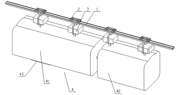
A suspension type tunnel rescue device (as shown in Fig. 1) which can quickly reach the rescue position through the top guide rails was designed. The suspension type tunnel rescue device consists of following parts:
- The guide rails mounted at the top of the tunnel.
- The wheels travel on the rails.
- A power plant system.
- A fire extinguishing system.
- A platform that is mounted below the wheel and travels along the tunnel.

(1. Rail; 2. Travel and Brake system; 3. Drive system; 4. Comprehensive platform; 41. Rescue carriage;
42. Fire-fighting carriage; 43. Exit)
One of the rescue carriage’s (41) function is to provide safe and fast delivery for the personnel who lose their mobility during the accident. The other function of the rescue carriage is to provide space for the equipment which is used for tunnel maintenance personnel. The elevator (43) in the lower part of the rescue carriage can not only provide passage transport for the rescued personnel, but also provide a plug-in work platform in order to carry out tunnel maintenance. The fire-fighting system can be connected with the tunnel fire hydrant after reaching the designated area, and firefighter can remotely control the fire extinguishing system in a secure location on the ground and complete the task of fire-fighting and protection of the tunnel structure.
2. EQUIPMENT COMPOSITION ANALYSIS
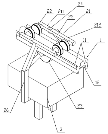
As shown in Fig. (2), the guide rail (1) has two openings which are an up rail groove (11) and a lower rail groove (12). The wheel (2) is comprised of a connecting frame (21), two pair of front and back guide wheels (22) and a driving wheel (23) which are arranged on the connecting frame. Each pair of guide wheels (22) is comprised of two guide wheels which are located in the two upper rail grooves, respectively. And the driving wheel (23) is located at the lower rail groove. The driving equipment (3) is mounted on the connecting frame (21) and drives the driving wheel. The platform (4) is connected to the bottom of the connecting frame (21). The connecting frame (21) is divided into a front connecting frame (211) and a rear connecting frame (212) between the two pairs of front and back guide wheels. The front and rear connecting frames are hinged through a hinge shaft (24) which is vertically oriented.

The integrated platform (4) assembles with a fire extinguishing system which comprises a hydraulic station equipped with a fire extinguishing medium, a spraying device for spraying the fire extinguishing medium and a pipeline for the flow of the fire extinguishing media.
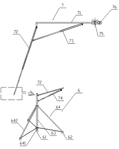
As shown in Fig. (3), the combined spray head is included by the spraying equipment (6). The combined spray head is composed of main spray head (61), a plurality of auxiliary spray heads (62) uniformly distributed along the circumferential direction. The bracket connects mian spray heads and auxiliary spray heads. The bracket is comprised of a main rod (63) and crank and slide block mechanisms (64) which make the main rod as fixed link and same as the number of auxiliary spray heads. All the cranks and slide block mechanisms (64) share one sliding block on the main rod. The main spray head (61) is located at the lower end of the main rod (63), and the auxiliary spray heads (62)are installed at the cranks belonging to crank and slide block mechanisms (64). The spraying equipment also comprises a mechanical arm (7), including the supporting arm (71) which is oriented on the vertical axis of the horizontal setting, the first telescopic rod (72) is hinged at one end of the supporting arm, and the second telescopic rod (73) which is respectively hinged at two ends of the supporting arm and the fixed end of the first telescopic rod, respectively. The main rod (63) is hinged on the output end of the first telescopic rod. The mechanical arm (7) also comprises the third telescopic rod (74) which is hinged at both ends of the main rod (63) and a fixed end of the first telescopic rod (72).
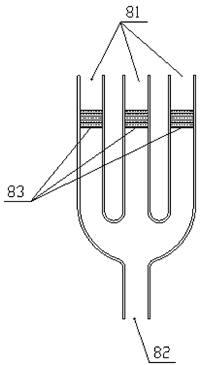
The hydraulic pressure station equips fire-fighting carriage (42) which contains the special fire extinguishing medium for tunnel. The connection pipe is provided with three inlets which are respectively connected to the foam extinguishing agent, inert gas and water and an outlet (82) connected with the main nozzle (61). The three inlets connect with the outlets (82) respectively through three one-way valves (83) as shown in Fig. (4). Meanwhile the auxiliary nozzle (62) is connected with the fire hydrant.

The platform also provides the thermal imaging equipment, the lighting system, daily maintenance platform (only used in the tunnel maintenance period), rescue ladder and the elevator which can fal1 to the ground.
3. THE IMPLEMENTATION OF THE DEVICE
As shown in Fig. (1), the platform (4) of the invention is distinguished into rescue platform (41) and fire-fighting platform (42) according to function. The rescue platform (41) is used to rescue trapped personnel. And the fire-fighting platform (42) is used to put out a fire. In detail, the rescue platform (41) adopts a closed compartment structure. And rescue workers conduct the operation of rescue and fire-fighting by taking a rescue platform to the rescued position. The elevator is set in the rescue platform, and it can pass the lifting port (43) which is in the bottom of the rescue platform to the ground. It can ensure a rapid rescue of injured person by using rescue platform (41). At the same time, the rescue platform is equipped with lighting system to facilitate and guide the rescue mission.
The fire extinguishing system is an active fire extinguishing system which itself contains a fire extinguishing media. The system contains a hydraulic power station which contains the fire extinguishing medium, a spraying device, and a pipeline which are sprayed out by the fire extinguishing medium. The hydraulic power station comprises a container provided with a fire extinguishing medium, a hydraulic pump and a control valve for providing power for the fire extinguishing medium. The fire extinguishing medium in the hydraulic power station is set in a certain pressure to reach the spraying equipment through the pipeline, and then spray the fire site through the spray equipment, such as the spray head. Because the hydraulic power station is provided with a high pressure system, the fire extinguishing system is provided with a water cooling channel for cooling the equipment in the hydraulic power station. The fire-fighting platform (42) is provided with a fire extinguishing system which is used to put out a fire and thermal imaging equipment to determine the location of the fire source in the condition of smoking, low visibility and poor environment.
Due to the existence of small curvature bending alone tunnel’s length direction or the others facilities located in the roof of the tunnel, the rail will bend to meet the tunnel shape or avoid interference. The platform could move freely on the condition that the guide wheels between before and after meet a certain angle. To this end, the horizontal frame (25) of the connecting frame (21) is composed of a front connecting frame (211) and a rear connecting frame (212), and the front and rear connecting frames are hinged by a hinge axis (24). Two front guide wheels are arranged on the front connecting frame (211), and the two rear guide wheels are arranged on the rear connecting frame (212). The vertical frame is arranged on the rear connecting frame (212), so that the turning of the front and back guide wheels can be realized.
The spraying device comprises a combined spray head (6) and a mechanical arm (7). The combined spray head (6) comprises a main spray head (61) and three auxiliary nozzles (62). Three auxiliary nozzles (62) are distributed on the circumference of the main nozzle (61) as the center. The main nozzle (61) is connected with the auxiliary nozzle (62) through a support, and the number of the auxiliary nozzle (62) can be set arbitrarily according to the process requirement. Foam fire extinguishing agent and inert gas fire extinguishing medium are contained in the hydraulic power station.
As shown in Fig. (4), the pipeline is provided with three inlets (81) and an outlet (61) connected with a foam extinguishing agent, an inert gas and water, and an outlet (82) connected with the main nozzle. The three inlets are respectively communicated with the outlet (82) through one-way valves (83). The auxiliary nozzle (62) to access the hydraulic station in the water, the auxiliary nozzle (62) spray mist to form a water curtain closed area. Main nozzle (61) is as main fire extinguishing nozzle. Open different one-way valves (83), you can choose to spray fire-fighting foam, inert gas and water. The hydraulic power station opens different one-way valve orderly according to the fire program, so as to achieve high efficiency of the fire.

The mechanical arm (7) are composed of a supporting arm which is horizontally arranged around the vertical axis (75) to rotate (71), a first telescopic rod (72) which is hinged at one end of the supporting arm (71), the second telescopic rods are respectively hinged on the fixed end of the supporting arm (71) and the first telescopic rod (72), the third telescopic rod which are respectively hinged on the main stem (63) and the telescopic rod (74) on the fixed end of the first telescopic rod (72). The main stem (63) of the combined spray head (6) is hinged on the output end of the first telescopic rod (72). The first, second and third telescopic rods are all hydraulic telescopic rods, and the structure form is the same as that of the hydraulic cylinders. It means that the piston rod can change the whole length of the telescopic rod in the cylinder body, the output end of the telescopic rod is the piston rod of the hydraulic cylinder, and the fixed end of the telescopic rod is a cylinder body of the hydraulic cylinder. The support arm is driven by a gear drive mechanism in platform ahead of front or rear of the direction of rotation at 180 degrees, so that the combination of nozzles (6) to full coverage in the width direction of the tunnel and realize the largest area of jet fire-extinguish.
3.1. Fire Rescue
The enclosed space of road tunnels supply rooms for smoke and heat which bring difficult to escape and rescue from the tunnel fires [11]. So when an emergency fire occurs in the tunnel, the command center receives a fire message, immediately determine the location of the fire source and choose the nearest device to enter the tunnel (Explanation: The devices are arranged in the tunnel inlet and outlet, so that they can quickly reach) according to the return data. Once arriving at the scene, the fire-fighting and rescue carriages separated immediately, and the rescue workers take the elevator to reach the ground quickly to put out a fire and investigate casualty situation, respectively.
Professional firefighters, preliminary according to the scene, immediately identify file source category and choose suitable extinguishing media to operate the fire extinguishing device (42) and control fire preliminary. At the same time, two fire fighters should be sent to find the tunnel fire hydrants, and connect the hydrants with the water pipe of the fire-fighting carriage to prepare for the following fire-fighting work.
Professional rescue and medical personnel perform t evacuation and medical rescue. Especially for those who were serious wounded and difficult to move, immediate emergency rescue should be taken and put them into the rescue carriage to take off the scene so as to get professional medical treatment in the shortest time.
When the fire occurs, the temperature can reach 1000 degrees Celsius, which is very destructive to the tunnel structure and the auxiliary facilities. Therefore, rapid cooling treatment should be conducted to avoid additional damage to the structure.
3.2. Detection and Maintenance
Regular maintenance and inspection of tunnel is essential to ensure a good operation level and plays an important role in lifeline engineering, especially for the long tunnel. Generally, the tunnel ventilation fan and the lighting system are much higher than the road surface, which brings troubles to the detection and replacement of non-blocking traffic. But the use of hanging maintenance platform can be very convenient to avoid the conflict. Upon receiving the tunnel inspection and maintenance instructions, the maintenance procedure will start:
Moving out the relevant rescue equipment within the rescue carriage, and to make space for the shipping inspection equipment and the replacement of tunnel facilities.
Installing the plug-in maintenance platform, tunnel testing related equipment, and equipped with the lamps, cameras, traffic signs and other items which need to replace.
Under the circumstances of not affecting the traffic condition, professional inspection and maintenance personnel control the maintenance platform to carry out testing tasks, while completing the maintenance of ancillary machinery and equipment.
CONCLUSION
This design can provide of rapid arrival to tunnel disaster prevention and perform the detection and maintenance operations for tunnel non-interrupt traffic. Next, we plan to develop prototypes, design and apply this design to a long tunnel. We believed that this design would improve the management and maintenance level of the tunnel, and ensure a safety operation during the service period.
CONFLICT OF INTEREST
The authors confirm that this article content has no conflict of interest.
ACKNOWLEDGEMENTS
This project was supported by Chongqing Outstanding Youth Found Project of CQ CSTC (cstc2014jcyjjq30001), Chongqing Key Laboratory of Traffic & Transportation (2016CQJY007).


