All published articles of this journal are available on ScienceDirect.

The Complex Monolithic Movement for the Brick-wooden Building in Deformation Analysis and Reinforcement
Abstract
This paper first analyzes the reasons of complex monolithic movement of a brick-wooden building in Henan province in China. The building foundation integral underpinning technique and curved-track moving technique which combine the track sharing-monolithic movement method and efficient long distance movement method were put forward. These methods use the anchor static pile, in order to guarantee the safety of the building for complex monolithic movement. The analysis of the internal force and deformation of underpinning structure was calculated by finite element software SAP2000. A practice case showed that the internal force of the underpinning structure is less than the bearing capacity, which proved the efficiency of the proposed method.
1. INTRODUCTION
There are different reasons why buildings have complex monolithic movement. One of the most important, deals with the soil properties of the buildings, which always have proper characteristics depending on the different regional areas [1]. Firstly, the movement of water often causes the uneven settlement of building foundation in less collapsible areas. Secondly, the foundation problem often produces differential settlement in soft-clay areas. At the same time, due to the improper investigation, design, construction and other human factors, often result in a greater differential settlement [2]. Different buildings structures show dissimilar resistance to the uneven settlement. Beyond the bearing capacity, the internal structure will be destroyed, and the buildings cannot function properly [3].
Different methods to analyze complex monolithic movement are used on different buildings for different moving reasons during the past decades [4]. However, the integral underpinning building foundation technique and curved-track moving technique are new comprehensive methods for the building complex monolithic movement [5]. Unlike the previous correction methods, the monolithic movement method is designed to use certain technology to move the vertical component on the specific concrete railway or air cushion, so as to force the structure to tilt.
The application of the building monolithic movement technology has been employed for over 100 years [6]. Comparing with the technology for moving out and reconstructing, there are more economic, social and environment-protection benefits [7]. However, the research about monolithic movement started late in our country. Now, the movement and reinforcement mainly depend on the sophisticated construction methods and designed techniques, but having no systematic theory or technique for reference.
This paper puts forward a systematic research on complex monolithic movement, including the reasons and the reinforcement methods, combined with an example of brick-wooden building in a yellow-clay area of Henan Province.
2. PROJECT OVERIEW
2.1. Project Introduction
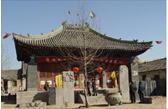
Ci-yuan temple is located in Anyang City, which was built in the Tang Dynasty. According to the local records, Ci-yuan temple experienced several repairs, in the existing three courtyards, during the Song, Yuan, Ming and Qing dynasties. The main buildings are the king hall, the main hall and three churches, which is the largest ancient building group with national recognized in 1999. From that time, Ci-yuan temple was named as the Henan provincial key cultural relics protection units.
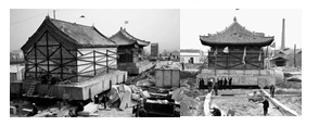
The temple sits north to south, with a length of 72 m and a width of 30m, within three courtyards. In the front yard, the gate and hatchback room have been removed. The Wen-chang Palace, located in the middle is basically stable, in which the hall and the west wing are still in use after repairing. While the backyard building, suffered much more significant damage, for example some of the roofs were collapsed. The three churches and two penthouses were part of on the original ancient architectural pedestal reconstruction. The surrounding facade is shown in Fig. (1).
2.2. The Soil Properties in the Site
According to the records, the site was originally a farmland and shallow pond, and it was filled with soil later. Moreover, the geological survey report concluded that, from top to bottom, the main kinds of the soil were plain fill, mucky soil, organic clay, silty clay, silt and circular-gravel. The miscellaneous fill strata and the soft soil were thick. The underground water sources were at 1.0m to 2.5m from the ground. The components of the soil and the main physical indicators are listed in Table 1. (GB 50007-2012 2012).
| Soil Strata Name |
Average Thickness Of the Soil (m) | Natural Water Content % |
Natural Void Ratio e 0 |
Natural Density ρ(g/ cm3) | Internal Friction Angle φ(0) |
|---|---|---|---|---|---|
| Plain Fill | 4.5 | 33.55 | 0.91 | 1.77 | 10.26 |
| Mucky Soil | 3.5 | 70.36 | 1.868 | 1.59 | 3.89 |
| Organic Clay | 3.5 | 61.93 | 1.66 | 1.64 | 5.83 |
| Silty Clay | 3 | 36.00 | 0.99 | 1.85 | 7.75 |
| Silt | 3 | 38.12 | 1.05 | 1.83 | 11.51 |
| Circular-gravel | 1 | 16.03 | 0.45 | 2.1 | — |
3. CAUSE AND ANALYSIS OF COMPLEX MONOLITHIC MOVEMENT
There are many kinds of reasons for the uneven settlement and differential settlement of the buildings in soft soil foundation. Through the actual research and geological prospecting situation, we found that the main reason for the uneven settlement of our case is in two parts, loads from the superstructure and historical value.
Compared with other remnants of ancient buildings, the most typical difference is that the Ming Ci-yuan Temple is representative brick masonry arch buildings. There is no doubt that these buildings are full of traditional timber-framed landing gear. If the buildings are rebuilt, they will experience a great deal of destruction.
Moreover, from the point of view of the architectural history value, there is no doubt that Ci-yuan temple’s safety must be guaranteed. By means of comparing three solutions: the cofferdam protection, site migration and monolithic movement. Afterwards, according to the reasons above, the experts decided on the scheme of site migration by monolithic movement because it offers the higher value overall translation protection.
4. REINFORCEMENT MEASUREMENT
4.1. Reinforcement Scheme
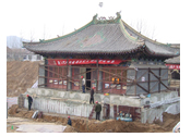
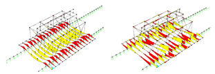
Reinforcing the structural strength means to control the internal forces and deformation to guard the integrity of the structure. The specific design here is to build an in vitro steel system, which will be tightly wrapped to the heritage building. Moreover, the key parts of the heritage building with strengthening needs special protection, to ensure the heritage body rigidity. The overall stiffness and strength to external force are necessary to enhance the tartget buildings, including the ground disturbances and structural deformation due to unfavorable loads. The in vitro steel system is depicted in Fig. (2).
4.2. The Building Foundation Integral Underpinning Technique Scheme
4.2.1. The Finite Element Analysis Model for the Mechanical Properties of Underpinning Structure
4.2.1.1. Determination of Vertical Bearing Capacity of Single Pile in Antistress Wall
The bearing capacity of the foundation soil to the pile is composed of the pile tip resistance and the side friction resistance.
Quk=u∑qsikli+qpaAp
where:
Quk — single pile vertical bearing capacity value, (kN);
qsik — the limit side resistance “I” form pile (kPa);
qpa — limit side resistance characteristic value (kPa);
u — For supporting a prefabricated pile perimeter u,(m);
li — length of a pile in the soil of “I” layer, (m);
Ap — area of the end section, (m2).
To verify the actual carrying capacity of the stirring cored pile, under foundation beams, six piles were selected for the static load test as shown in Table 2. Obviously, pile #3 had an ultimate bearing capacity greater than the designed value of 900 kN; the capacities of piles #5-#9 reached 540 kN, which is much smaller than the design value. Thus, the bearing capacity of a single pile did not meet the design requirements; this was one of the main reasons leading to the uneven settlement of the building.
4.2.1.2. The Connection of Rail Beam and Foundation
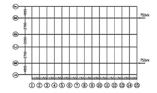
According to the engineering design requirements, first the loose soil layer of the base surface must be removed, whose compaction coefficient is not less than 0.94, and its compacted soil thickness is not less than 1000mm. In the compacted 450mm thick lime soil, compaction coefficient is not less than 0.96. The dust must be compacted according to the design requirement of pouring walking track beam. In theoretical calculation, vertical springs are assumed to simulate the effect of the foundation on the track beam, the horizontal restriction of the track beam is applied to prevent horizontal displacement. The underpinning structure analysis model and top thrust action point is shown in Fig. (3).
| Stirring cored pile number | Estimated ultimate bearing capacity design / kN | Test pile Length / m |
Maximum loading / kN |
Maximum Settlement /mm |
Vertical Ultimate Bearing Capacity / kN | Corresponding settlement / mm |
Corresponding Loading / kN |
|---|---|---|---|---|---|---|---|
| 3# | 950 | 10.0 | 900 | 16.29 | ≥900 | 16.29 | 850 |
| 5# | 950 | 10.0 | 810 | 46.15 | 540 | 10.67 | 743 |
| 6# | 950 | 10.0 | 630 | 55.91 | 540 | 12.88 | 600 |
| 7# | 950 | 10.0 | 630 | 69.05 | 540 | 17.94 | 600 |
| 8# | 950 | 10.0 | 900 | 53.95 | 540 | 16.36 | 850 |
| 9# | 950 | 10.0 | 720 | 60.40 | 540 | 12.31 | 690 |
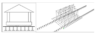
From SAP2000 software explicit dynamic analysis modules, wooden structure can be simulated with semi-rigid nodes, because wood is a heterogeneous, anisotropic material, and its strength is affected by many factors such as: grain direction, defects, composition and growing environment. According to wood material’s strength, the points of theoretical calculation and analysis are as follows. Horizontal rod axial stiffness U1:1.26×10⁶kN/mm, vertical rod axial rigidity U2, U3: 1.41×10⁶kN/mm, rotational stiffness R1, R2, R3: 1.50×10⁶kN/mm. In this paper, an equivalent diagonal trust model is simplified, which is considered in the form of equivalent diagonal braces. The rail beam configuration is shown in Fig. (4).
4.2.1.3. The Result of Analysis for Underpinning Structure Stress Results
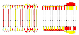
According to the bending moment diagram of the beam in the direction of gravity which is shown in Fig. (5), one beam is single span and the other is the cantilever beam. The maximum bending moments between positive beam and the track beam are supported equally.
From the calculation of the section analyzer which builds in SAP2000 according to the model, the numerical simulation can be shown that the axial force of the support beam which is smaller than that of the cross section bearing capacity relatively. The maximum axial force of the beam is 32719kN, which is much larger than the maximum axial force generated in the single beam and cantilever beam both in vertical and deflection. Therefore, it shows that the beam has enough strength in the process of underpinning, which can ensure the safety of the process of the monolithic movement, as shown in Fig. (6).
According to the results of the finite element analysis of the underpinning structure, it can be seen that the edge beam and the side beam can cooperate with each side, and the internal force of each beam is in the range of safety, and the deflection value of each bracket is smaller. The whole underpinning structure has sufficient strength and rigidity to ensure the reliability of the construction process.
4.2.2. Multivariate Statistical Methods
In order to control the degree of tilting back during the monolithic movement, the settlement of the building must be observed. A monitoring system is set up on the site in the program of the monolithic movement, with two methods of the measurement in the field, the leveling measuring method and the dial indicator observation. These two methods became complementary to each other to ensure the accuracy of the observation [8].
4.2.2.1. The Leveling Measuring Method
The electronic level measurement is used in the settlement observation, 2 level basis points are laid on the foundation without external disturbances, which is beyond the range of the foundation deformation. Meanwhile, the elevations of the basic points are corrected regularly, which will ensure the standard of the point elevation values would not have any changes. The necessary measures are taken to ensure the buildings safe after the monolithic movement in accordance with the settlement monitoring data in time.
4.2.2.2. The Dial Indicator Observation
During the monolithic movement of the building, the dial indicator observation is often used for the correction value of the building. However, errors may occur due to the soil settlement in this dial indicator observation, so this observation is combined with the leveling measuring method to get the value accurately. During the process of the monolithic movement, the larger relatively stiff areas are chosen to set the dials, the monitoring points are observed frequently, the monitoring data is calculated, and the situation of tilting back is reported in time. The dials are shown in Fig. (7).
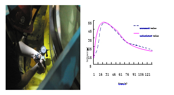
Meanwhile, it could be seen from the curve of the settlement observation that after the monolithic movement, the settlement was gradually stabilized. Moreover, it is indicated that the settlement stopped if the results of the monitoring settlement are basically unchanged till the next week. The rectification of the building had lasted 56 days. The maximum inclination rate and the architectural distortion was stabilized.
4.3. The Curved-track Moving Technique Scheme
The process of construction is as follows: (1) According to the main hall and the three churches of the whole body, which in turn shift in bend rail need local widened as track. (2) During the shift process, the steel shaft and even small amplitude adjustment angle should not appear, in order to change the direction of arc moving. (3) During the shift process, a rear end and the middle part of the small track is reduced in the corner on the track in front of a small part of the rail in front of the building. (4) As the steel shaft process which is used for adjusting the angle, therefore the local compression which the resistance should be increased at the same time by jacking force. Field test indicates that the top thrust is increased by 30%-50%. The whole process is shown in Fig. (8).
CONCLUSION
Through the successful implementation of the complex monolithic movement of the brick-wooden building, the following understandings in engineering design and construction are achieved.
- (1) The factors of the surrounding environment and history value of the temple are the major causes of the complex monolithic movement and reinforcement.
- (2) It is feasible to use a comprehensive building foundation integral underpinning technique method to combine the track sharing-monolithic movement method combined with efficient long distance movement method, featured by short time constructions and quickness of movement and safe.
- (3) It is not possible to control precisely the rate of the movement, because many factors affect the process. Therefore, only by information-oriented construction method can take measures to control the rate timely. It is not only the detection method of the effect for the monolithic movement, but a more effective means of controlling rate of the complex monolithic movement.
Based on the analysis of this case, it will provide beneficial references for similar projects in the future, which having great value added in the near future.
CONFLICT OF INTEREST
The authors confirm that this article content has no conflict of interest.
ACKNOWLEDGEMENTS
The work was accomplished within the the Coal Joint Fund of the National Natural Science Foundation of China and Shenhua Group (U1261126); the Fundamental Research Fund for the Central Universities (2010YL09)

